Direct measurement of superluminal group velocity and of signal velocity
in an optical fiber
Abstract
We present an easy way of observing superluminal group velocities using a birefringent optical fiber and other standard devices. In the theoretical analysis, we show that the optical properties of the setup can be described using the notion of ”weak value”. The experiment shows that the group velocity can indeed exceed in the fiber; and we report the first direct observation of the so-called ”signal velocity”, the speed at which information propagates and that cannot exceed .
The physics of light propagation is a very timely topic because of its relevance for both classical [1] and quantum [2] communication. Two kind of velocities are usually introduced to describe the propagation of a wave in a medium with dispersion : the phase velocity and the group velocity . Both of these velocities can exceed the speed of light in vacuum in suitable cases [3]; hence, neither can describe the speed at which the information carried by a pulse propagates in the medium. Indeed, since the seminal work of Sommerfeld, extended and completed by Brillouin [4], it is known that information travels at the signal velocity, defined as the speed of the front of a square pulse. This velocity cannot exceed [5]. The fact that no modification of the group velocity can increase the speed at which information is transmitted has been directly demonstrated in a recent experiment [6]. Superluminal (or even negative) and, on the other extreme, exceedingly small group velocities, have been observed in several media [7]. In this letter we report observation of both superluminal and delayed pulse propagation in a tabletop experiment that involves only a highly birefringent optical fiber and other standard telecom devices.
Before describing our setup, it is useful to understand in some more detail the mechanism through which anomalous group velocities can be obtained. For a light pulse sharply peaked in frequency, the speed of the center-of-mass is the group velocity of the medium for the central frequency [3]. In the absence of anomalous light propagation, the local refractive index of the medium is , supposed independent on frequency for the region of interest. The free propagation simply yields where is the length of the medium and is the free propagation time. One way to allow fast- and slow-light amounts to modify the properties of the medium in such a way that it becomes opaque for all but the fastest (slowest) frequency components. The center-of-mass of the outgoing pulse appears then at a time , with the mean time of arrival once the free propagation has been subtracted; obviously for fast-light, for slow-light. If the deformation of the pulse is weak, the group velocity is still the speed of the center-of-mass, now given by
| (1) |
This can become either very large and even negative () or very small () — although in these limiting situations the pulse is usually strongly distorted, so that our reasoning breaks down.
We can now move to our setup, sketched out in Fig. 1. The medium is a birefringent optical fiber of length , whose refraction index is for the telecom wavelength 1550 nm. The fiber is sandwiched between two polarizers. This setup is also known in classical optics as a Lyot filter [8]. As shown in [9], this simple situation can be described with the quantum formalism of weak values [10]. In fact, the three essential ingredients of weak values are present here: (I) The input polarizer allows the pre-selection of a pure polarization state . (II) The birefringent fiber performs a pre-measurement of polarization by spatially separating the two fiber’s eigenmodes, supposed to be described by the eigenstates and of — that is, we choose to be the birefringence axis. This pre-measurement, known in telecom physics as polarization-mode dispersion (PMD), is weak whenever the temporal shift (the so-called differential group delay, DGD) between the two eigenmodes of the fiber is much smaller than the coherence time of the optical pulse. (III) The output polarizer performs the post-selection on another chosen polarization state . The mean time of arrival of the optical pulse can be expressed as a function of a weak value [9, 1]:
| (2) |
where is the polarization obtained by the free rotation of in the fiber. Thus, is in principle unbounded: by carefully choosing and , i.e the direction of each polarizer, one can tune the group velocity (1) to any desired value. In summary, by appending two polarizers at the ends of a birefringent fiber, one creates an effective medium whose dispersion and absorption properties depend on the pre- and post-selection; in this effective medium, the group velocity can be increased or decreased by an arbitrary amount by merely choosing the orientations of two polarizers.
The rest of the paper is organized in three parts: first we derive the optical properties (dispersion and absorption) of our effective medium, stressing the role of the weak value . Then we describe the experiment and present our main results in Figs 4 and 5. We shall conclude by comparing our experiment to a related one [11], and by stressing the differences with other fast- and slow-light techniques.

Theoretical analysis. For any linear medium in which light propagates, the absorption coefficient and the index of refraction are defined through
| (3) |
where is the length of the fiber, and where is the linear response function which characterizes the evolution of a plane wave of frequency in the medium: . The calculation of for the effective medium sketched in Fig. 1 has to take polarization into account. The first polarizer prepares the state
| (4) |
where and are the eigenmodes of the fiber, the eigenstates of the Pauli matrix for the eigenvalues . As discussed in Ref. [9], the evolution of the polarization of the plane wave because of birefringence is given by the unitary operator , which describes a global rotation around the axis of the Poincaré sphere — with our conventions, is the slow mode and is the fast mode. So, the state that reaches the second polarizer is where one recognizes the phase acquired during free propagation through the fiber and where
| (5) |
The second polarizer is represented by the projector on a polarization state . So the output state reads with a response function [12]
| (6) |
where we have written and , and where
| (7) |
is the weak value involving the orientations of the two polarizers [13]. Note that this is not the weak value that enters the mean time of arrival (2): that one is computed using instead of ; using (5), one obtains
| (8) |
From (3) and (6) it is straightforward to derive expressions for the absorption coefficient and the index of refraction . For simplicity, the global phases of both polarization states and are chosen such that is real and contributes thus only to the absorption. The results are:
| (9) | |||||
| (10) |
From , one can derive the group index . Using (8) and (2) one finds
| (11) |
This gives exactly the behavior (1) for the group velocity — indeed, both derivations are based on the assumption that the coherence time of the pulse is large compared to . When is small, the second term in (11) disappears and : this is normal propagation, obtained for most choices of the pre- and post-selection. The conditions are obtained for the slow, resp. the fast, polarization mode of the fiber, , resp . When , we obtain the slow-light regime; when , the fast-light regime. In particular, since , superluminal group velocity () requires , negative group velocity () requires .
In fig. 2, the absorption coefficient (9) and the index of refraction (10) are plotted for different weak values. When increases, the slope of the index of refraction becomes steeper: a larger positive (negative) group delay corresponds to a slower (faster) group velocity. It is also clear from fig. 2 that a strong absorption occurs whenever the change in the group velocity is important. Although these features are usual in their qualitative formulation, we note (as the authors of Ref. [11] did) that the standard Kramers-Kronig relations do not apply: these relations predict that the absorption coefficient (”imaginary part of the index”) determines uniquely the index of refraction (”real part”), and viceversa; while in our case, the same absorption is associated to different dispersions. Modified Kramers-Kronig relations have been discussed in [14]. However, a full study of the question lies beyond the approach presented here, because our formula (6) for is valid only in a limited frequency range — e.g., the index of the fiber is not constant over all possible frequencies.

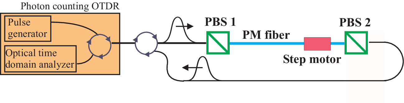
Experiment. The experimental setup is sketched out in fig. 3. As a source and for detection we use an optical time domain reflectometer (OTDR). This is a telecom instrument designed to measure loss profiles of fibers: it sends short laser pulses and analyzes the amount of back-scattered light as a function of time. Here we use a commercial prototype OTDR working in photon counting mode at the telecom wavelength m [15]. It contains a pulsed DFB laser (MHz , pulse duration 2 ns) and a gated peltier-cooled InGaAs photon counter (gate duration 2 ns). The photon counting OTDR is well adapted to this experiment since it allows to monitor the optical pulse, even in the presence of strong absorption. The birefringent fiber is a polarization maintaining (PM) fiber of length m, with a DGD ps, measured with an interferometric low-coherence method [16]. The fiber is placed between two polarizing beam splitter (PBS) cubes with specified extinction ratios of 50 dB. Both cubes are mounted on rotational stages, allowing a precise alignment of pre- and post-selected polarization states. Furthermore a micrometer step motor permits to slightly change the length of the fiber. This allows alignment of the post-selection also in the plane of the Poincaré sphere, since polarization is rotating around the axis in the fiber.
The crucial part of the experiment is the alignment of both PBS cubes. The input polarizer has to be aligned at relative to the fiber’s axis [17]. This is done by injecting incoherent light (from a LED) into the system and minimizing the degree of polarization at the output of the PM fiber. For the post-selection, the position of the second PBS cube and the length of the fiber are adjusted such that transmission through the system is minimum.
A first set of results is presented in fig. 4. Figure (a) shows the data of a sequence of successive measurements on a dB scale. The largest curve is the reference pulse, i.e. the pulse in the normal regime, without any specific alignment of the PBS cubes. Between each measurement the post-selection is slightly changed, in order to decrease transmission: we observe that the lower the transmission, the higher the group velocity, in agreement with the theory. In addition, figure (a) clearly illustrates the difference between group and signal velocities [4]. In fact, even though the group velocity is higher for each successive curve, the signal velocity remains constant and equal to , since the front parts of all pulses are strictly identical. Figures (b) and (c) show, respectively, a fast- and a slow-light example. The measured data are plotted together with the reference pulse (dashed curve) and a fit (smooth solid curve). The fit is obtained by applying the following transformation to the observed intensity of the reference pulse : , where FFT is a discrete Fourier transform procedure. The first step of this fitting procedure assumes the reference pulse to be Fourier-transform limited; the slight discrepancies found between the data and the fits (in the front and back parts of the pulses) are probably due to this approximation. The fitting parameter is the weak value , supposed to be real. Note that in (b), lies below , the value needed in order to demonstrate superluminal group velocity. To reach that bound, much longer input pulses are needed. We replace the OTDR source by an external source: a DFB laser ( MHz) working in CW mode, modulated by an external electro optic modulator (EOM). This source creates nearly gaussian pulses with a coherence time of about 50ns. The OTDR is still used for detection and triggers the modulator. Results are presented in fig. 5. The pulse on the right shows clearly superluminal group velocity. By fitting the position of the maximum of the output pulse [18], we find , consistent with superluminal but non-negative group velocity, as expected.
Comparison with other experiments. Solli and co-workers reported on a similar, but indirect, experiment using polarized microwaves and a photonic crystal as birefringent medium, with identical conclusions on the group velocity [11]. Their conclusions were extracted from phase measurements only, so in particular they had no result on the signal velocity.
Most experiments on slow light have been performed using electromagnetically induced transparency (EIT) [7, 19]. In EIT, the mode that carries information can be transmitted without losses, which is not the case in our experiment.
In conclusion, we presented an easy way to create slow and fast light using a birefringent optical fiber and other standard telecom components. The theoretical part of this work was mainly devoted to the study of the linear response function of our system , that is determined by a weak value, thus extending the previous work of [9]. In the experiment, we obtained clear evidence for superluminal group velocities (fig. 5); we also gave the first direct measurement of the ”signal velocity” [fig. 4 (a)], showing that the increase of the group velocity does not increase the speed at which information travels.
We thank C. Barreiro for technical support. This work was supported by the Swiss NCCR ”Quantum photonics”.
References
- [1] B. Huttner, C. Geiser and N. Gisin, IEEE J. Sel. Top. Quantum Electron. 6, 317 (2000).
- [2] D. Bouwmeester, A. Ekert and A. Zeilinger (eds), The physics of quantum information (Springer, Berlin, 2000).
- [3] J. D. Jackson, Classical Electrodynamics, 2nd edition (Wiley, New-York, 1975), Sect. 7-8.
- [4] L. Brillouin, Wave propagation and group velocity (Academic Press, New York, 1960).
- [5] Actually, some weak excitations called ”forerunners” may arrive even before the main front, but not faster than c. Their speed has been called, somehow unfortunately, ”front velocity”.
- [6] M. D. Stenner, D.J. Gauthier and M. Neifeld, Nature 425, 695 (2003)
- [7] R. W. Boyd, D. J. Gauthier, Progress in Optics Vol. 43, edited by E. Wolf (Elsevier, Amsterdam, 2002)
- [8] W. Demtröder, Laser spectroscopy (Springer, Berlin, 2003)
- [9] N. Brunner, A. Acín, D. Collins, N. Gisin, V. Scarani, Phys. Rev. Lett. 91, 180402 (2003)
- [10] For a review see: Y. Aharonov and L. Vaidman, quant-ph/0105101; published in: J.G. Muga, R. Sala Mayato, I. L. Egusquiza (eds), Time in Quantum Mechanics, Lecture Notes in Physics (Springer, Berlin, 2002).
- [11] D. R. Solli, C.F. McCormick, C. Ropers, J.J. Morehead, R.Y. Chiao, J.M. Hickmann, Phys. Rev. Lett. 91, 143906 (2003).
- [12] We have found a scalar response function because we have pre- and post-selected on pure polarization states. In general, the response function will be tensorial, relating the polarization components [11].
- [13] A more complex link between response functions and weak values in a similar situation was pointed out in: D. R. Solli, C.F. McCormick, R.Y. Chiao, S. Popescu, J.M. Hickmann, Phys. Rev. Lett. 92, 043601 (2004).
- [14] J.S. Toll, Phys. Rev. 104, 1760 (1956)
- [15] M. Wegmüller, F. Scholder, N. Gisin, J. Lightwave Tech. 22, 390 (2004)
- [16] N. Gisin, J.P. Pellaux, J.P. von der Weid, IEEE J. Lightwave Technology 9, 821 (1991)
- [17] It can be easily shown from (2) that this pre-selection maximizes the mean time of arrival .
- [18] We were not able to correctly fit the shape of these curves. This is probably due to a saturation of the OTDR detection or to some phase noise that invalidates the first step of the fitting procedure.
- [19] S. Harris, Physics Today, July 1997; M.D. Lukin, A. Imamoğlu, Nature 413, 273 (2001).

