Geometric quantum gate for trapped ions based on optical dipole forces induced by Gaussian laser beams
Abstract
We present an implementation of quantum logic gates via internal state dependent displacements of ions in a linear Paul trap caused by optical dipole forces. Based on a general quantum analysis of the system dynamics we consider specific implementations with alkaline earth ions. For experimentally realistic parameters gate infidelities as low as can be obtained.
pacs
03.67.Lx, 03.65.Vf, 32.80.Lg, 32.80.QkI Introduction
Today, one of the most promising physical systems for an experimental realization of quantum computation is a string of trapped ions Cirac and Zoller 1995. In such a realization, a quantum bit (qubit) is represented by two internal states of an ion on which quantum logic operations can be performed through laser-ion interactions. Any quantum logic operation can, e.g., be composed of single-qubit operations and Controlled-NOT (CNOT) gates between any two ions in the string DiVincenzo 1995. While single-qubit gates are relatively simple to perform, the CNOT and equivalent two-ion gates are more demanding and usually also slow as compared to single-ion gates. Only very recently such two-ion gates have been demonstrated experimentally Schmidt-Kaler et al. 2003; Leibfried et al. 2003. One class of two-ion gates is the geometric quantum gates, which can be relatively fast as compared to other two-ion gates and furthermore allows a high fidelity since the internal states of the ions are not directly involved in the gate operation Leibfried et al. 2003; Sørensen and Mølmer 2000.
In this paper we present a proposal for an experimental realization of a geometric quantum gate. The idea underlying our gate proposal is that internal state dependent optical dipole forces applied to a pair of ions will displace their equilibrium positions in the trap in proportion to the forces acting on them. Their relative distance is thus modified, and the associated shift of their Coulomb potential energy gives rise to a complex phase factor which depends on the internal states of both ions, and which hence provides a non-trivial two-qubit gate.
The paper is organized as follows. In Sec. II we present a full quantum analysis of the dynamics of the system to obtain the correct values for the phase factors and to properly assess the effect on the atomic motion in the trap. In Sec. III, we consider specific implementations in alkaline earth ions. Assuming a Gaussian intensity profile of the applied laser beam, we find in Sec. IV experimentally relevant parameters for an implementation of the gate proposal using or ions and discuss relevant error sources. Finally, in Sec. V, we give a discussion and a conclusion.
II Theory
We consider a pair of ions confined to the trap axis of a linear Paul trap, i.e., the axis where the rf-field vanishes Ghosh 1995. A laser beam which is far-off resonant with all internal transitions in the ions and propagates perpendicular to the trap axis induces an optical dipole force. This force can be described by a potential which depends on the position variable along the trap axis, and on the internal state label taking one of two possible values, represented by and in the following. The potential is controlled by the intensity, waist, polarization, and wavelength of the laser beam Grimm et al. 2000.
For an ion string illuminated by a dipole force inducing beam its total potential energy, , is the sum of the dipole potential of each ion, the potential energy of the ions due to the trap and due to their mutual Coulomb repulsion. Specifically for two singly-charged ions of mass , we have
| (1) | ||||
where is the single ion oscillation frequency in the trap and where a linear expansion of the dipole potential around the equilibrium positions () has been applied. is the optical dipole force exerted on the ’th ion.
Rather than considering a CNOT gate, we shall in the following focus on implementation of the equivalent Controlled-Z two-qubit gate Nielsen and Chuang 2000. A Controlled-Z gate applied to a superposition of the product states , , and changes the sign of the term (i.e., the phase of this state is changed by ), while leaving the others unchanged. The implementation of a geometric Controlled-Z gate relies on the fact that the dipole force is internal state dependent. The origin of this dependence will be described in the next section. As mentioned above, the idea is that the dipole force displaces the ions away from their equilibrium positions, and the associated change in Coulomb energy gives rise to phase-shifts which depend on the internal states of the ions. By choosing a suitable temporal and spatial profile of the dipole force inducing beam, the obtained phase shifts of the above mentioned four product states can be made equivalent to a Controlled-Z gate.
To describe the motion of the ions, we first rewrite Eq. (1) as follows
| (2) | ||||
where are the motional mode coordinates for the so-called center-of-mass mode and the breathing mode James 1998, respectively, and denotes the equilibrium distance between the ions. Turning to a quantum mechanical description, we introduce lowering (raising) operators () and () for the mode coordinates, i.e., and , to find the Hamiltonian
| (3) | ||||
where
| (4) | ||||
| and | ||||
| (5) | ||||
are responsible for excitation of the center-of-mass mode and the breathing mode, respectively. The time-evolution of the system can be described by a unitary time-evolution operator , which evolves state vectors in time according to . solves the time dependent Schrödinger equation, . Since the Hamiltonian can be decomposed as a sum of commuting terms, can be expressed as a product
| (6) | ||||
where and are time-evolution operators corresponding to the Hamiltonians
| (7) | ||||
| and | ||||
| (8) | ||||
respectively. In the following we solve for with the understanding that the solution can be obtained from simply by replacing with and with . To this end, we switch to the interaction picture with respect to the Hamiltonian of the free harmonic oscillator
| (9) | ||||
| and make the Ansatz that | ||||
| (10) | ||||
From the Schrödinger equation for it follows that the harmonic oscillator phase-space displacement , with being the center-of-mass mode momentum, can be written as
| (11) | ||||
| and that the phase acquired due to excitation by the force term is given by | ||||
| (12) | ||||
The displacement of the ions is internal state dependent, which leads to coupling (or entanglement) between the internal and the motional states. For the gate operation, this is an undesired effect and we shall therefore request the displacement to be zero at the end of the gate operation, such that . In the implementation of the Controlled-Z gate described below, we will take the dipole-potential to be of the form , in a time interval and zero otherwise, specifically with outside this interval. To avoid the large internal state dependent phase factors in Eq. (6) we furthermore assume . The force term can be written as , which together with Eq. (11) implies that the center-of-mass mode displacement at the end of the gate operation can be written
| (13) |
Both terms of this expression vanish if is an integer number of oscillation periods, , and if the Fourier transform
| (14) | ||||
From Eq. (12) it can be shown that the phase acquired during the gate operation can be expressed as
| (15) | ||||
where is the Fourier transform of and and are constants. The first term on the r.h.s. is irrelevant, since it does not depend on the internal state of the ions and the second term vanishes since we have required . The interesting term is the last one, from which we observe that the closer the characteristic frequencies of the function are to the oscillation frequency (or for the breathing mode), the larger is the accumulated phase. It is thus a natural choice to adopt a harmonic time dependent force that oscillates with just one oscillation cycle less (or more) than the trapping motion during the interaction time . In Fig. 1(a), one example of a phase-space trajectory of the center-of-mass mode of two ions in the state is shown. The duration of the interaction is taken to be 15 trapping periods, and 14 periods of the applied periodic force. We observe that the net displacement vanishes at the end of the gate operation. For the same interaction, Fig. 1(b) shows the phase-space trajectory of the breathing mode with the ions being in the state. The breathing mode frequency of is far-off resonant with the frequency of the applied force and hence the breathing mode is much less excited than the center-of-mass mode. Note that since , this oscillator mode undergoes an almost integer number of oscillations and hence it experiences a nearly vanishing net displacement at the end of the gate operation. Other good choices for the duration of the interaction in units of the trapping period are 56 (), and 209 (). The phases are equal to the areas of the phase-space trajectories in units of , and they depend on the internal state of both ions, as needed for a two-qubit gate. Fig. 1(c) shows the build-up of the phase during the interaction. The parameters have been chosen to ensure an effective phase shift of on the state (see Eq. (33) below) as desired for the Controlled-Z gate. In the following section on the physical implementation of the scheme, analytical expressions for the acquired phases are provided.

III Implementation in alkaline earth ions
III.1 Atom-light coupling
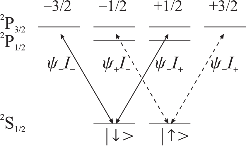
Since alkaline earth ions are among the most prominent atomic ions for doing quantum logic, we will now focus on experimental realizations of the Controlled-Z gate based on such ions with presentations of specific results for and . We choose the qubit states to be and , on which single qubit operations can be performed using Raman transitions via the level. Assuming that the frequency of the dipole force inducing laser is close to or below the transition frequencies and of the – and the – transitions, respectively, we may to a good approximation only consider contributions from these two transitions to the dipole potential (as long as is not in the immediate vicinity of the transition frequencies of the weak electric quadrupole transitions). Expanding the dipole force inducing beam into - and -polarized light components with respect to its propagation axis (the quantization axis), the contributions to the dipole potential for the two states and are those associated with the transitions indicated in Fig. 2. The respective dipole potentials can consequently be written
| (16) |
where is the intensity of the - and -polarized components, respectively, and where
| (17) | ||||
| and | ||||
| (18) | ||||
depend only on the properties of the ion and the frequency of the dipole force inducing laser. Here, and are the transition strengths of the – and the – transitions, respectively. As can immediately be seen, the force derived from this dipole potential will be different for the two qubit states, whenever the intensities of the two polarization components differ. Hence, by introducing a sinusoidal temporal variation of the intensity of the polarization components given by
| (19) |
which can be done by, e.g., using an electro optic phase modulator, the situation considered in Sec. II can be obtained.
From Sec. II we thus identify for . As for the choice of , we recall the requirements with integer, and that the characteristic frequency of , i.e., , should be close to . Consequently, a good choice is with , as in the example of Fig. 1 where . The Fourier transform of on the interval contains two terms which are proportional to and , respectively. These sinc-functions peak at and , while they have exact zeros at and . Furthermore, they are suppressed at , especially when is close to an integer.
III.2 Phase shifts
In order to calculate the displacement and the acquired phase for the center-of-mass mode and the breathing mode, respectively, for the specific intensity variation in Eq. (19), the -functions entering in the integrals in Eqs. (11) and (12) have to be determined using the definitions in Eq. (4) or (5). For , which is responsible for excitation of the center-of-mass mode, we find
| (20) | ||||
| (21) | ||||
| (22) | ||||
| (23) | ||||
| where | ||||
| (24) | ||||
| (25) | ||||
| (26) | ||||
| and | ||||
| (27) | ||||
The full time-dependent expressions and , which were used for obtaining the plots in Fig. 1, can be found by carrying out the integrals in Eqs. (11) and (12) for the center-of-mass mode as well as the breathing mode Staanum 2004. Here we only state the acquired phases at the end of the gate operation, which for the center-of-mass mode are given by
| (28) | ||||
| (29) |
neglecting a term which is independent of the internal state and assuming . These phases scale quadratically with with one factor of originating from the time and the other originating from the denominator, due to the fact that was chosen to be near-resonant with . The phases acquired due to excitation of the breathing mode are likewise found to be
| (30) | ||||
| (31) |
where
| (32) |
These phases only scale linearly with , since the rotation frequency is off-resonant with the breathing mode frequency of . In Eqs. (30) and (31), terms which are smaller than the stated terms by a factor of and further suppressed if is close to an integer have been neglected.
The combined effect of the above phase shifts is equivalent to a single phase shift of the state Sasura and Steane 2003. Thus, to make a Controlled-Z gate, we require that
| (33) | ||||
IV Realization of the Controlled-Z gate using gaussian laser beams
IV.1 Intensity requirements and off-resonant scattering rates
In the following we will consider possible realizations of a Controlled-Z gate in a two ion string using one or two dipole force inducing laser beams propagating perpendicular to the trap axis as sketched in Fig. 3. In the first case shown in Fig. 3(a), we assume that the equilibrium distance between the two ions is smaller than the waist of the laser beam, such that they feel essentially the same strong dipole force. The situation in Fig. 3(b) corresponds to a case where the size of the force on the two ions are the same but of opposite sign for identical internal states. Finally, Fig. 3(c) shows a realization similar to the first case, but with application of two laser beams.
Since in all cases we will assume the ions to be situated close to one of the points in the intensity profile where the induced dipole force is largest, much of the analysis is similar for the three situations. Hence, in the following we will focus on the situation in Fig. 3(a) in order to establish formal equations. Assuming the ion string is centered at , we may write the intensity of the dipole force inducing beam as
| (34) |
where is the center of the dipole force inducing beam, is the beam waist and is the peak intensity. For the gate operation two highly relevant and linked parameters are the required peak intensity and the fidelity loss due to off-resonant scattering events. The required peak intensity enters in Eq. (33) through the -functions. For a given wavelength and a given choice of beam waist the required peak intensity can be determined. Using the definitions in Eqs. (25), (26), (27) and (32), we find , and a pair of non-zero expressions for and , which together with Eq. (33) yields the required peak intensity
| (35) |
where only the leading term in has been retained. The scaling with the various parameters is intuitively reasonable. First, it has already been discussed that large leads to a large phase pick-up and hence a low intensity requirement. Second, the larger the difference , the larger is the dipole force difference for and . Third, if the waist is small, the dipole force is large, which in turn reduces the required intensity. Note also that the required laser power () is proportional to , which makes a small waist very attractive.
Knowing the required intensity, we can now determine the average probability for a scattering event from one of the two ions during the gate operation. Formally, we can write (), where is the average total scattering rate of the two ions. Assuming an equal average population of the two internal states and an intensity of at the position of the ions, the dominant scattering from the - and the -state yields
| (36) | ||||
| where | ||||
| (37) | ||||
The dependency of on the internal structure of the ion and the wavelength of the dipole force inducing laser is contained in the front factor of , showing that can be minimized either by making small or large. becomes small in the limit due to the factor of , however, in the same limit is proportional to the difference , which is also small. Alternatively, if , can become a sum of two positive terms, however, for to be small in this case, a large fine-structure splitting is required. Both in the far-off resonant case and when the dipole force inducing laser is tuned in between the fine-structure levels, the ion turns out to be more attractive than the ion. Another candidate ion is which for the present gate proposal is less attractive than but more attractive than , however, in the following we only consider and .

IV.2 Experimental parameters for and
To get more quantitative numbers out, we now consider the cases of two or two ions in a trap with , which leads to an equilibrium distance of 5.6 and 3.7 between two ions, respectively. First we consider the situation depicted in Fig. 3(a) for , such that the dipole forces on the two ions are equal. To fulfill this we choose a waist of . Finally, by choosing () the intensity and the scattering rate can be calculated for a given wavelength of the dipole force inducing laser beam. For and with the dipole force inducing laser tuned either in between the fine-structure levels or far red detuned, we find the following values for (Power, , ), where is the dipole force inducing laser wavelength. : (8, 30, 395.1) and (0.5, , 1500). : (86, , 474.5) and (33, , 1000). Clearly, this is not very promising for experimental realizations. However, since the main problem is the requirement that , the situation depicted in Fig. 3(b) is more favorable. Here with the ions positioned symmetrically around the center of the dipole force inducing beam. Since we do not have the requirement that we can choose a lower trap frequency of , which implies that is equal to 16.4 for and 10.9 for and which yields the following values for (Power, , ). : (120, 8%, 395.1) and (6.5, , 1500). : (360, 1%, 474.5) and (140, , 1000). For high fidelity gates the required power is experimentally still too demanding.
Finally, we consider the situation presented in Fig. 3(c) where the waist of the applied laser beams is not directly related to the equilibrium distance between the ions and hence rather tightly focussed beams can be applied. As long as the beam waists are larger than the thermal excursion of the ions from their equilibrium positions, the equations derived above for the case of Fig. 3(a) is immediately applicable. For and , we plot in Fig. 4 the required laser power and for and as a function of the dipole force inducing laser wavelength. The plots in Fig. 4(a,c) extend to a wavelength of in order to show the long wavelength behavior, however, one should keep in mind that due to diffraction it is technically demanding to obtain a 5 waist for the longest wavelengths. In all plots was chosen, which gives a very reasonable gate time of .
(a)(b)


(c)(d)


For , we see from Fig. 4(a) that a high power of is required in the long wavelength limit for the considered parameters. However, by choosing instead of 15, the required power drops to at the cost of an increased gate time of . Considering the challenge of diffraction a laser at a wavelength of 2 would be favorable in the long wavelength limit. Fortunately, the required power of is easily achievable with commercial Thulium fiber lasers operating in the range of 1.75 - 2.2
11endnote: 1 High power single mode Thulium fiber laser from IPG photonics (TLR-series), www.ipgphotonics.com.. Hence, high fidelity gates with should be possible. Other interesting lasers in the far-off resonant regime are the Nd:YAG (yttrium aluminium garnet) laser at 1064 and the CO-laser near 5, but the relatively high scattering probability and diffraction limitations, respectively, makes these lasers less attractive than the Thulium fiber laser. A wavelength near 395 is furthermore attractive for (see Fig. 4(b)), since the needed power of only easily can be obtained. The scattering probability is a few percent, which is acceptable for a first demonstration, but not good enough for implementation of error correcting schemes. By a further reduction of the beam waist, e.g., by placing a lens system inside the vacuum chamber where the ion trap is situated, it should be possible to focus to below 1 Schlosser et al. 2001 and hence reduce the scattering rate by a factor of .
Due to the larger fine-structure splitting of , the scattering probability is already below 1% for a wavelength around 475 (see Fig. 4(d)) between the – transition wavengths. The low laser power needed in this wavelength region can easily be supplied by frequency doubled diode laser systems. Note also that light from an Argon-ion laser at a wavelength of 488 could be a reasonable possibility. However, as for a Thulium fiber laser seems to be most ideal, since high fidelity gates with (a value comparable to the threshold value required for fault-tolerant quantum computation Steane 2003) should be feasible with laser powers of about 14 for the case with and as shown in Fig. 4(c). In the long wavelength limit, the 1064 wavelength of a Nd:YAG laser could also be a possibility since a scattering probability of at a laser power of is achievable. It should be noted that in all cases discussed above, the required power, the scattering probability and the gate time can be adjusted by changing , and .
IV.3 Error sources
When we considered the realization of the gate schemes above, we already discussed the effect of spontaneous emission on the fidelity of the gate operations. There are, however, other experimental error sources which will also influence the final fidelity of an actual realization. A key element in the present gate proposal is the polarization rotation, which serves to remove phases due to internal state dependent Stark shifts. Since the Stark shifts are of first order in intensity and the phase acquired by the change in Coulomb energy only originates from second order effects, even small errors in the laser parameters may be very critical to the actual gate operation. In the following subsections, errors due to non-perfect balancing of the two polarization components of the dipole force inducing laser beam, timing errors as well as power, position and frequency-fluctuations of the dipole force inducing laser are discussed.
IV.3.1 Polarization errors
In case there is an imbalance of the intensity in the two polarization components, such that
| (38) |
where accounts for the imbalance, there will be two extra terms in the dipole potential. One term [] enters with the same sign in and and hence it does not give rise to any Stark-shift induced phase-difference between and . The other term, , enters with a different sign in and , which leads to a phase-difference of between and in each ion at the end of the gate operation. Since this difference should be much smaller than the desired phase-shift of , we find by using the expression for , Eqs. (34), (35) and the condition
| (39) |
In the situation considered above with and this means for and for . Fulfilling these criteria is not very easy, but fortunately, the undesired phase-difference can be cancelled by using a type of spin-echo technique Allen and Eberly 1975. Instead of generating the full effective phase-shift of in a single operation, the gate-operation can be performed in four steps: (1) Run the gate at half the intensity, to get an effective phase-shift of on . (2) Swap the population between and by applying single-qubit -pulses to both ions. (3) Same as (1). (4) Same as (2). The trick here is that the undesired phase-differences due to a polarization error, which are obtained in step (1) and (3), are of the same magnitude but have opposite signs (due to the population swapping) and therefore cancel out. The gate operations in (1) and (3) both give an effective phase-shift of , even though the population is swapped in (2), because and . The final -pulse just swaps the population back. Using this trick the gate time is doubled (neglecting the duration of the relatively fast -pulses), while the required intensity is halved. Since the required intensity is proportional to and the gate time , these parameters can be re-adjusted if an appropriate value for is available.
Finally, the imbalance also gives rise to errors in the gate operation, which the spin-echo trick does not cancel. These errors are of order or and hence they are suppressed to the level at a small but realistic value of .
IV.3.2 Timing errors
In case the gate time differs from the duration of a full number of polarization rotation periods, an undesired phase-difference will again build up. Assuming and , the phase-difference is equal to above, with the replacement . Again using and and considering with , Eq. (39) translates to , with a more relaxed limit for larger (the limit is proportional to ). Applying electro optic modulators to control the laser pulse length, the condition on is not very severe since switching times of a few nanoseconds can be obtained.
IV.3.3 Power fluctuations
If the total laser power fluctuates at a frequency , such that the total intensity is given by , then the resulting fluctuations in the dipole potential integrated over the gate time will give rise to a phase difference between and . If the intensity fluctuations are random, they can in general not be expected to cancel using the spin-echo trick. When the phase difference , i.e., the same phase-difference as above, just with replaced by , which means that is required for . When the phase-difference is smaller by a factor of and even smaller if . Intensity stabilization fulfilling is not unrealistic, in fact a commercially available Laser Power Controller already offers a power-stability of within certain limits
22endnote: 2 Laser power controller from Brockton Electro Optics, www.brocktoneo.com..
IV.3.4 Position fluctuations
Fluctuations in the position of the dipole force inducing beam give rise to intensity fluctuations, which lead to imperfect cancellation of the Stark-shift induced phase and an unwanted variation in the dipole force exerted on the ions. Hence, for high quality gate operations with errors at the level, position jitter has to be of the order of of the beam waist or smaller. This condition is most restrictive for the situation shown in Fig 3(c), where a pointing stability of about 50 nm is needed when . Though small, this type of stability is technically possible.
IV.3.5 Frequency fluctuations
As for the power and position fluctuations, laser frequency fluctuations will lead to fluctuations in the dipole potential and hence to an imperfect cancellation of the Stark-shift induced phase. Since laser frequencies can be very accurately controlled and frequency fluctuations anyway are expected to be small, as compared to the detuning from any of the two fine-structure levels, this is not expected to play any significant role.
V Discussion
The gate proposal presented above has some similarities with the gate recently demonstrated by the NIST group Leibfried et al. 2003; in fact the mechanism which gives rise to the desired phase shift is exactly the same. There are, however, also some essential differences between the two schemes.
In the NIST experiment, a dipole force along a given trap axis was provided by the intensity-gradient of a moving standing wave light-field. The wavelength of the light-field and hence the period of the standing wave is set by the requirement that the Stark-shift induced phase shift of the two qubit levels should be zero (corresponding to in our case), which is fulfilled if the laser is tuned in between two fine-structure levels. This can, however, give rise to a significant amount of scattering events, as we also saw above. Even though this scheme relies on a moving standing wave, the instantaneous force on the two ions is required to be equal. Consequently, the ions have to be well localized which requires cooling to the Lamb-Dicke limit with respect to the wavelength of the light-field, which in this case also is the Lamb-Dicke limit for the qubit operations. An equal dipole force on the two ions was obtained by adjusting the distance between them to an integer number of standing wave periods, which may be difficult to generalize to perform a gate between any two ions in a multi-ion string.
In the proposal presented here, where the dipole force is provided by a variation in the beam-profile, the excursion of the ions from their equilibrium position should only be smaller than the beam waist, which is adjustable, but typically up to ten times larger than a relevant transition wavelength. This means that except for very tightly focussed beams the Lamb-Dicke limit criterion need not be fulfilled and, specifically, the ions need not be cooled to the motional ground state. Since the dipole force inducing beam propagates perpendicular to the ion-string in our proposal, addressing of specific ions for implementation of gates in a multi-ion string should be feasible. A theoretical description of this situation should also be quite straightforward by generalizing Eq. (6). Finally, owing to the polarization rotation method, the dipole force inducing laser is allowed to be far-off resonant with respect to the relevant internal transitions, such that a scattering probability below the asymptotic threshold value required for fault-tolerant quantum computation Steane 2003 in principle can be obtained in the long wavelength limit.
It should be mentioned, that the idea of using optical dipole forces for implementing a Controlled-Z gate has also been considered by Sasura and Steane for an array of microscopic ion traps with a single ion in each trap Sasura and Steane 2003. In many respects this system is very similar to the one considered here and naturally many of the considerations are the same as those made above.
In a very recent proposal, Garcia-Ripoll, Zoller and Cirac present a geometric gate, where the momenta of the involved ions are controlled by absorption of photons from a discrete set of laser pulses Garcia-Ripoll et al. 2003. In this case requirements on the pulses naturally arise for having zero displacement and for obtaining the desired phase shift. It can be shown that these requirements are discrete versions of those expressed through above.
In conclusion, we have presented a proposal for a geometric quantum gate and shown that an experimental realization using the attractive alkaline earth ions and is feasible with gate times below 100 and errors at the level as required for fault-tolerant quantum computation Steane 2003.
References
- Cirac and Zoller (1995) J. I. Cirac and P. Zoller, Phys. Rev. Lett. 74, 4091 (1995).
- DiVincenzo (1995) D. P. DiVincenzo, Phys. Rev. A 51, 1015 (1995).
- Schmidt-Kaler et al. (2003) F. Schmidt-Kaler, H. Häffner, M. Riebe, S. Gulde, G. P. T. Lancaster, T. Deuschle, C. Becker, C. F. Roos, J. Eschner, and R. Blatt, Nature 422, 408 (2003).
- Leibfried et al. (2003) D. Leibfried, B. DeMarco, V.Meyer, D. Lucad, M. Barrett, J. Britton, W. M. Itano, B. Jelenkovic, C. Langer, T. Rosenband, et al., Nature 422, 412 (2003).
- Sørensen and Mølmer (2000) A. Sørensen and K. Mølmer, Phys. Rev. A 62, 022311 (2000).
- Ghosh (1995) P. Ghosh, Ion Traps (Clarendon Press, Oxford, 1995).
- Grimm et al. (2000) R. Grimm, M. Weidemüller, and Y. B. Ovchinnikov, Adv. At. Mol. Opt. Phys. 42, 95 (2000).
- Nielsen and Chuang (2000) M. A. Nielsen and I. L. Chuang, Quantum Computation and Quantum Information (Cambridge University Press, Cambridge, 2000).
- James (1998) D. James, Appl. Phys. B 66, 181 (1998).
- Staanum (2004) P. Staanum, Ph.D. thesis, University of Aarhus, Denmark (2004).
- Sasura and Steane (2003) M. Sasura and A. M. Steane, Phys. Rev. A 67, 062318 (2003).
- Schlosser et al. (2001) N. Schlosser, G. Reymons, I. Protsenko, and P. Grangier, Nature 411, 1024 (2001).
- Steane (2003) A. M. Steane, Phys. Rev. A 68, 042322 (2003).
- Allen and Eberly (1975) L. Allen and J. H. Eberly, Optical resonance and two-level atoms (Dover Publications, New York, 1975).
- Garcia-Ripoll et al. (2003) J. J. Garcia-Ripoll, P. Zoller, and J. I. Cirac, Phys. Rev. Lett. 91, 157901 (2003).