Quantum cloning with an optical fiber amplifier
Abstract
It has been shown theoretically that a light amplifier working on the physical principle of stimulated emission should achieve optimal quantum cloning of the polarization state of light. We demonstrate close-to-optimal universal quantum cloning of polarization in a standard fiber amplifier for telecom wavelengths. For cloning we find a fidelity of 0.82, the optimal value being .
Classical information can be copied at will. Not so for the information content of a quantum state: one cannot devise a process that takes copies of an arbitrary quantum state as an input, and produces copies of the same quantum state deterministically. This is the content of the no-cloning theorem of quantum mechanics [1], which is at the heart of quantum information theory (in particular, it guarantees the security of quantum cryptography). To go beyond this no-go theorem, one can weaken the requirements, and ask that the copies are not identical to the input state, but as close as possible to it [2, 3]. The physical device that performs this operation is called quantum cloning machine. A device that copies equally well all the possible input states is called universal quantum cloning machines (UQCM).
In the recent years, communication through optical fibers has become widespread, and everybody knows that a light signal can be amplified. But light can (should) be described quantum-mechanically, therefore the standard amplification devices used in telecom cannot beat the no-cloning theorem.
It is not difficult to understand why some noise will always be produced by the amplifier: the amplification of light is achieved through stimulated emission, and it is well-known that in this case spontaneous emission will always be present as well. But it has been noticed recently [4] that the amplification based on stimulated emission leads to optimal cloning. To see this, describe the amplifier as an ensemble of atoms initially in the excited state, that can emit photons polarized either along any direction with equal cross-section. The atoms are irradiated with a photon of the suitable energy, polarized along a direction . At the exit of the amplifier, we select the cases in which one and only one additional photon has been emitted, and analyze the output in the basis. If is the probability that the additional photon is polarized along (spontaneous emission), then the probability that the additional photon is polarized along is because of stimulated emission. Now, if we pick one photon of the output at random, the probability of this photon to be in the same state as the input photon (namely ) is called fidelity of the cloner. In the case that we are considering, the fidelity is , which is indeed the optimal fidelity for a universal cloning machine [2]. This easy reasoning has been extended to any amplification process in Ref. [4]; we re-derive the main results below.
According to this theoretical prediction, an amplifier whose gain is independent of the polarization is a UQCM for the polarization states of photons. Amplification through parametric down-conversion has been considered [4, 5, 6, 7]. In this Letter, we demonstrate an amplification in an Er-doped fiber that is very close to optimal cloning.
We begin by reviewing some theoretical elements on cloning and amplification, while stressing the links with our experiment. The setup itself and the results are described in detail in the second half of the Letter.

Cloning of polarization states. An experiment to demonstrate universal cloning of polarization states consists of three blocks (fig. 1): the preparation, the amplification (cloning) and the analysis. The source prepares photons in the same polarization mode, say . The photons are sent into the amplifier, supposed to be non-birefringent to ensure that any input polarization is amplified in the same way (universal cloning). Suppose that at the output of the amplifier one selects the events in which exactly photons have been produced. According to the no-cloning theorem, it is impossible that all photons are deterministically in the state : some of the photons at the output have been produced in the orthogonal mode because of spontaneous emission, and will consequently be reflected at the polarizing beam splitter (PBS). Thus the process is characterized by the probabilities that the output photons are distributed as: photons in the mode , and photons in the orthogonal mode , with :
| (1) |
We normalize these probabilities so that , the probability of the process . The fidelity of the process is defined as the fraction of photons that are found in the same mode as the input:
| (2) |
with . If the amplification process is based on stimulated emission with no absorption, then all the are proportional to the probability of the spontaneous emission through the binomial factor [8]
| (3) |
Inserting these probabilities into (2), one recovers exactly the optimal fidelity for a cloning [3]:
| (4) |
Note that this result is independent of or : these quantities are in general difficult to calculate, which means that one doesn’t know how frequent the process is (see [4] for estimates in some limiting cases). Nevertheless, each process that takes place would show the optimal fidelity if it could be isolated from the other processes.
Photon statistics. The two-dimensional quantum degree of freedom (qubit) that we want to clone is the polarization of photons. More precisely, one qubit corresponds to one photon per mode. Our source does not produce a Fock state of photons, but a continuous light signal, with weak power . Its spectral density is centered at the frequency and has a width width . In this context, the concept of photon is introduced as the energy quantum: writing , with the coherence time, we see that the input power corresponds to an average of photons per spatio-temporal mode, that is per coherence time. Our source produces states of photons, this number being statistically distributed with a distribution , with average . In principle, one could then use a fast photon detector to count the number of photons per time-modes, but this is not possible in practice for the coherence time used in our experiment. However, a measurement of the intensity is a direct way of measuring the mean values of the photon statistics.
The input light is polarized along a direction that we label . After the amplification stage, the PBS allows the measurement of the intensities in each polarization mode, that is the mean numbers of photons and . The fidelity is defined as above: the fraction of photons that is found in the same polarization mode as the input light, that is [9]
| with | (5) |
In other words, we are performing an experiment on light amplification in the weak intensity regime. Can one extract information about the underlying quantum cloning processes from such a measurement?
A great insight is gained by describing our experiment with a semi-classical theory of light amplification. Since we measure only mean intensities, we can simply take eq. (14) in the seminal paper by Shimoda et al. [10], and write it in our notations for each of the modes and :
| (6) |
The two parameters and are not independent, but are determined by the microscopic details of the process. is the gain due to stimulated emission [11]; can be used as a figure of merit for the UQCM. In fact: means no absorption, in which case we know (see above and [4]) that all underlying processes have the optimal fidelity. When , the absorption compensates exactly the emission; in this case, we have also . This means that the gains and losses in the amplifier compensate each other, and all the additional intensity comes from spontaneous emission. This is obviously the worst possible cloning machine [12].
The formulas (6) relate the gain to , and as . Inserting this into the fidelity (5), we obtain
| (7) |
Note that for the r.h.s. is formally the same as the optimal fidelity (4), but here and need not be integers. For instance, if , and , we have and . In conclusion: in the absence of absorption, the mean fidelity is the optimal fidelity for the mean numbers of photons. This somewhat astonishing result is a new manifestation of the deep link between the classical and the quantum description of light that has been stressed in a recent historical review of laser physics [13].
The setup. We proceed to the detailed description of the experimental setup. In the scheme (fig. 2), one recognizes the realization of each of the three blocks: preparation, amplification and analysis.
To prepare the polarized photons, we use a source of unpolarized light [14] followed by a linear polarizer that achieves an extinction ratio of about 21dB between the two orthogonal polarizations. An adjustable attenuator is then used in order to tune the power. This attenuator is also useful to prevent the light coming from the amplifier to be back-reflected into the circuit, which would create a hardly controllable ghost signal.
The spectrum of the source is wide; a band-pass tunable filter can be used to reduce the spectral width to the desired value around the working wavelength nm. This tunable filter is actually placed after the amplifier so that both the signal and the amplified light are filtered through it. This is not a nuisance since the light at different wavelengths does not disturb the process of amplification (this is because we inject a very low power compared to the saturation level of the amplifier). The filter sets the width of the optical mode , thus defining the power corresponding to one photon per mode.
The second block of the setup is the amplifier (the cloning machine), which consists of a few tens of centimeters of pumped Erbium-doped fiber (EDF). We note that a commercial amplifier (consisting of meters of EDF) would not be suitable for our experiment, since it is optimized to achieve a gain much higher than the ones we want. The pump is a 980nm laser with output power 120mW, thus making the fiber an inverted medium capable of amplifying a signal around 1550nm. The pumping is done backward with respect to the signal in order to limit residual pump at the output. Since the pump and the signal have different wavelengths, the separation of the signal from the pump is done by wavelength division multiplexers (WDM) at both ends of the EDF. The WDM between the source and the EDF is used to avoid pump light to disturb or destroy the source apparatus. At the other end of the EDF we put two WDMs, the second one acting as a filter for the light which is back-reflected from the first one.

The third block is the analyzer. It consists of an adjustable linear polarizer, together with a polarization controller and a single power-meter. With the polarization controller, one can align the setup so that on of the axes of the adjustable polarizer corresponds to the polarization of the input signal, while the orthogonal mode is the ”noise”.
Measurement protocol and results. Before starting the experiment, one must optimize the working wavelength, align the analyzer, and determine the losses in the circuit in order to calibrate the measurement of and .
The working wavelength is chosen with the tunable pass-band filter, with a width in wavelength of about 1nm. It is determined experimentally at 1555nm by searching, within the range of the filter, the best emission-over-absorption ratio, i.e. the wavelength where the absorption is minimized but the gain is not zero. The alignment of the polarization controller in the analyzer is performed by generating a signal at the source but leaving the pump off.
The losses in the circuit must be determined precisly because the relevant experimental quantities to demonstrate cloning are the power at the entry of the EDF, giving , and the power corresponding to each polarization mode at the exit of the EDF, giving and . The polarization-dependent loss of the whole circuit is due mainly to the filter; we measure it using the fluorescence of the pumped EDF without signal — by the way, this light is found to be totally depolarized, meaning that all the polarizations will be cloned equally well as desired. The losses in the analyzing block, including the two WDMs, are measured using a tunable laser to avoid measuring losses due to the reduction of the spectral width. We note that the fidelity calculated using (5) does not depend on the losses nor on the error on the losses, because these are multiplicative factors that cancel out in the division. Thus the estimation of can be made with high precision.
The power at the entry of the EDF is calibrated using the signal from the source, with the adjustable attenuator set to a reference value, and of course without pumping the EDF. At the analysis power-meter, we measure the power corresponding to the spectrum-window defined by the filter, from which we must deduce the losses in the output circuit and inside the fiber. For this calibration the absorption inside the EDF itself must be precisely determined. We found an attenuation of 0.25dB. With this procedure, we know the value of corresponding to each position of the adjustable attenuator.
For the experiment, the pump is turned on. The input power is scanned using the adjustable attenuator. For each mean power in the input, the mean power corresponding to (resp. ) is determined by reading the value at the power-meter when the polarizer is aligned along the input state (resp. its orthogonal state), and deducing only the losses of the analyzing block.
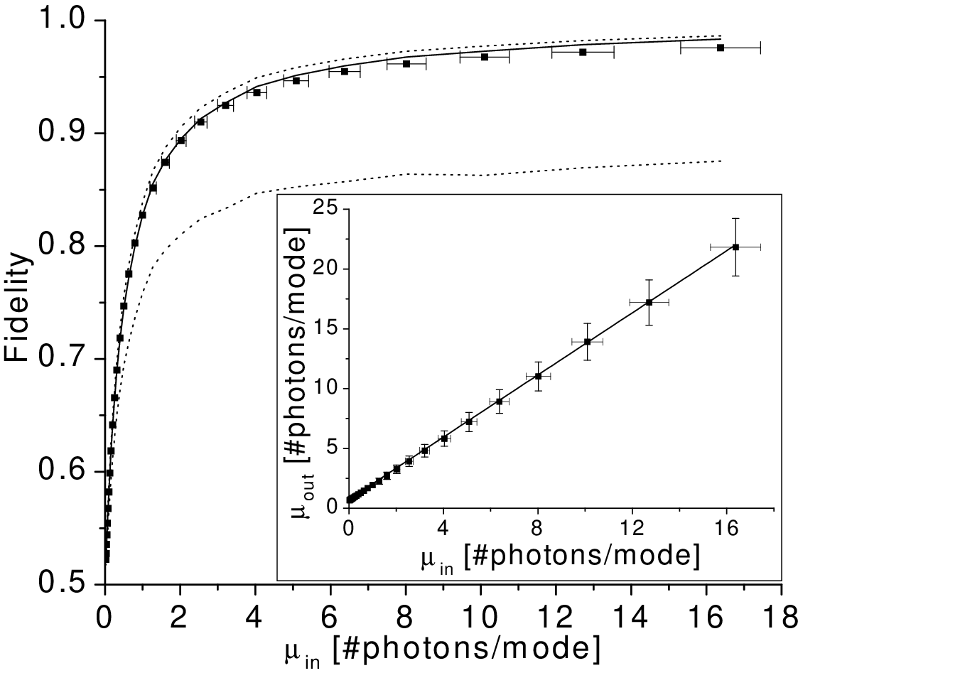
The length and the doping of the EDF have been chosen in order to achieve the desired gain at the working wavelength. The measurements presented here where made on a commercial EDF (INO Er103), 37cm long. With these values, we have a mean number of photons in the output for a mean number of photons in the input .
The experimental results are shown in fig. 3. In the inset, we show that a linear relation holds between and for all the input powers, in agreement with formulas (6). From our data, we extract the values of the two parameters and . We find and .
In the main part of the figure, we show the data for the fidelity calculated from (5), as a function of the mean number of photons in the input. The solid line correspond to eq. (7) with . The dotted lines correspond respectively to the optimal cloner (, upper line) and the worst cloner (, lower line). The experimental curve is clearly close to the optimal cloner, which confirms that , the parameter describing the absorption in the amplifier, is indeed a good figure of merit.
In conclusion, we have demonstrated close-to-optimal quantum cloning of the polarization state of light using a standard fiber amplifier working on the physical principle of stimulated emission. Since the amplifier is not birefringent, it acts as a universal cloning machine. On the side of application: An universal cloner is the optimal device for an eavesdropper to attack the six-state protocol of quantum cryptography [15], while a better strategy can be chosen to attack the four-state protocol [16]. The results of this Letter show that the physical realization of this device is not a very hard step; it will however be much harder for Eve to store the photons and wait for Alice and Bob to reveal the bases [17]. On the fundamental side, we like to conclude by stressing again the discussion about eq. (7). Quantum cloning could have been noticed and measured in the early days of laser physics; but it was not, because the notion of information was not yet central in science and consequently the quantum community was not aware of the fundamental role of the concept of (im)possible copying.
References
- [1] W.K. Wootters, W.H. Zurek, Nature 299, 802 (1982); P.W. Milonni, M.L. Hardies, Phys. Lett. A 92, 321 (1982)
- [2] V. Bužek, M. Hillery, Phys. Rev. A 54, 1844 (1996)
- [3] N. Gisin, S. Massar, Phys. Rev. Lett. 79, 2153 (1997); D. Bruss et al., Phys. Rev. Lett. 81, 2598 (1998)
- [4] C. Simon et al., Phys. Rev. Lett. 84, 2993 (2000); J. Kempe et al., Phys. Rev. A 62, 032302 (2000)
- [5] F. De Martini et al., Opt. Comm. 179, 581 (2000)
- [6] A. Lamas-Linares et al., Science 296, 712 (2002)
- [7] Y.-F. Huang et al., Phys. Rev. A 64, 012315 (2002); H.K. Cummins et al. Phys. Rev. Lett. 88, 187901 (2002). These two experiments are not based on amplification, but on transferring part of the information onto a different degree of freedom initially in a blank state.
- [8] This can easily be seen by modelling the amplifier as a chain of atoms that start all in the excited state, and having the initial photon distribution evolving according to the following rule: If an atom is irradiated by V-photons and H-photons, the probabilities of emitting one additional photon in either mode are linked by — and there is of course a probability that no additional photons are emitted by the atom.
- [9]
In terms of the individual processes, the average fidelity reads
However, this expression is hard to estimate, because we don’t know the . - [10] K. Shimoda et al., J. Phys. Soc. Japan 12, 686 (1957). For the process that we consider, holds in the notations of the paper.
- [11] That is, the ratio between [-spontaneous emission] and .
- [12] We don’t even consider the case , which would mean that the absorption overrates the emission, that is, that the amplifier is actually an absorber!
- [13] W.E. Lamb et al., Rev. Mod. Phys. 71, S263 (1999)
- [14] As a source, we use the spontaneous emission of a commercial Erbium-doped fiber amplifier.
- [15] D. Bruss, Phys. Rev. Lett. 81, 3018 (1998); H. Bechmann-Pasquinucci, N. Gisin, Phys. Rev. A 59, 4238 (1999)
- [16] C.-S. Niu, R.B. Griffiths, Phys. Rev. A 60, 2764 (1999); V. Scarani, N. Gisin, Phys. Rev. Lett. 87, 117901 (2001)
- [17] S. Félix et al., J. Mod. Opt. 48, 2009 (2001)