Quantum limits of cold damping with optomechanical couplingThanks: Unité mixte de recherche de l’Université Pierre et Marie Curie, de l’Ecole Normale Supérieure associé et du Centre National de la Recherche ScientifiqueThanks: website: www.spectro.jussieu.fr/Mesure
Abstract
Thermal noise of a mirror can be reduced by cold damping. The displacement is measured with a high-finesse cavity and controlled with the radiation pressure of a modulated light beam. We establish the general quantum limits of noise in cold damping mechanisms and we show that the optomechanical system allows to reach these limits. Displacement noise can be arbitrarily reduced in a narrow frequency band. In a wide-band analysis we show that thermal fluctuations are reduced as with classical damping whereas quantum zero-point fluctuations are left unchanged. The only limit of cold damping is then due to zero-point energy of the mirror.
PACS : 42.50.Lc, 05.40.Jc, 04.80.Nn
I Introduction
Characterization and control of thermal noise is of particular interest for very sensitive measurements such as interferometric gravitational-wave detectors[1, 2]. Fluctuations of the mirror position result from the thermal excitation of various mechanical modes of the suspended mirrors, corresponding either to external degrees of freedom of the suspension system or to acoustic modes of the mirror substrate. This leads to undesirable displacements of the mirrors and limits the sensitivity of the measurement. For example internal thermal noise is due to deformations of the mirror surface and constitutes the main limitation of gravitational-wave detectors in the intermediate frequency domain.
Thermal fluctuations are associated with dissipation mechanisms inherent in the system[3, 4, 5] and are therefore very difficult to avoid. Apart from passive methods such as the modification of mechanical damping[6] or cryogenic methods to lower the temperature[7], these thermal fluctuations may be reduced by using active systems. In particular it has been proposed to use an optomechanical displacement sensor to monitor the brownian motion of a mirror [8, 9]. Cold damping techniques have also been studied to reduce the effective temperature of a system well below the operating temperature[10, 11]. They have been proposed to reduce the brownian motion of an electrometer[12] and used to achieve very high sensitivity in accelerometers developped for fundamental physics applications in space[13].
Such techniques have been successfully applied to an optomechanical system composed of a high-finesse cavity and a feedback loop[9, 14]. The displacement of the mirror is measured by the optical Fabry-Perot cavity with a very high sensitivity[15, 16]. This information is fed back to the mirror via the radiation pressure of an intensity-modulated laser beam. For an appropriate design of the feedback loop, the radiation pressure exerted on the mirror is proportional to the mirror velocity. The servo-control force then corresponds to a viscous force. In contrast to passive damping which is necessarily accompanied by thermodynamic fluctuations[5], this active damping does not add any thermal noise and allows to greatly reduce the brownian motion of the mirror. Power noise reductions around the mechanical resonance frequency of the mirror as large as 1000 have been experimentally obtained. As proposed in [9] such short cavities could in principle be used to monitor the mirrors of a gravitational-wave interferometer. They would be insensitive to a gravitational wave and allow to reduce the mirrors thermal noise without affecting the response of the interferometer to the gravitational signal.
In the experimental conditions of references[9, 14], quantum effects are negligible as compared to thermal noise so that a classical treatment of the system is satisfactory to fit the experimental results. The analysis of electromechanical devices has provided precise discussions of the classical limits of cold damping[17]. It has in particular been pointed out that thermal fluctuations of position can be reduced by electronic damping of the motion without classical limit[18].
For an analysis of the actual limits of cold damping techniques, it is however essential to consider quantum fluctuations[11]. It is well known that quantum fluctuations play a fundamental role in the limits of sensitivity for interferometric position measurements. The respective role of the phase noise of the detection beam and of its intensity noise through radiation pressure effects on the mirrors has been thoroughly analysed. This has led to the definition of a standard quantum limit [19, 20] and of an ultimate quantum limit [21]. Reduction of quantum noise of light has also motivated studies on the behaviour of quantum noise in presence of active feedback[22, 23]. It has been shown that this technique allows to eliminate back action in quantum measurements[24] or to reduce quantum fluctuations of a light beam inside a feedback loop below the standard quantum limit, allowing an increased sensitivity of measurements [25].
With the optomechanical system, it is possible to reduce the initial temperature of the mirror and to improve the experimental efficiency of the cooling. This opens the way to a quantum regime of cold damping and raises several questions. For passive systems, in the limit of a null temperature, thermodynamic fluctuations associated with dissipation reproduce the quantum fluctuations required by Heisenberg inequalities[26]. What happens to the fluctuations of an actively cooled system? Does cold damping allow to reduce quantum fluctuations as it does with classical fluctuations? Is there a temperature limit for this technique? Do the quantum fluctuations of light introduce a limit in the efficiency of the cooling process? How is it possible to reach the limits?
In this paper, we address these questions by a quantum analysis of cold damping with optomechanical coupling. We use a theoretical treatment based on quantum networks theory[27, 28]. This approach allows to treat in the same framework both thermal and quantum fluctuations, for passive as well as for active elements[11, 29]. This quantum description ensure the consistency of the approach and allows to study the effect of cold damping for very low initial temperature. It has for example been proven fruitful in the analysis of quantum limits for ultrasensitive measurements with cold damped capacitive accelerometers[11].
We show that the only limit of cold damping are zero-point quantum mechanical fluctuations of the mirror, in agreement with general thermodynamical relations and Heisenberg inequalities[26]. This limit originates in our system from quantum fluctuations of the light beam used in the displacement measurement. As in the case of interferometric measurements, quantum noise of light limits the sensitivity of the measurement by the high-finesse cavity, and quantum fluctuations of radiation pressure disturb the mirror motion. In contrast with interferometers, however, radiation pressure effects are controlled by the active feedback. It is then possible to reduce the mirror fluctuations down to the zero-point quantum mechanical fluctuations, by an appropriate optimization of the cold damping mechanism.
In section II we present the optomechanical transducer composed of the high-finesse cavity and the feedback loop. Basic relations of cold damping mechanism are derived in section III.
In section IV we analyze the quantum limits for the reduction of mirror thermal noise on a narrow frequency band around the mechanical resonance. We show that it is possible to reduce this noise to arbitrary low values.
In section V we consider the whole noise spectrum of the mirror motion. We show that the temperature may be reduced to zero with a noise spectrum corresponding to zero-point fluctuations of the mirror.
We finally establish in section VI the general limits of noise in cold damping mechanisms. We show that the optomechanical system may provide a mean to reach these limits. The effects of this active technique are then equivalent to a coupling with a thermodynamic reservoir at a null temperature.
II Optomechanical transducer
The general scheme of the system is shown in figure 1. It is based on a measurement of the thermal noise of the mirror and on a feedback loop which applies a properly adjusted force on the mirror. The mirror is the end mirror of an optomechanical transducer made of a single-port high-finesse cavity resonant with the incident laser beam. Detection of the phase of the reflected field provides a signal proportional to the mirror displacement. This signal is used to implement the feedback loop via the radiation pressure of an intensity-modulated laser beam reflected from the back of the mirror. This modulated beam exerts a force proportional to the mirror displacement with a transfer function that can be tailored by the electronics. In order to apply a viscous damping force, the transfer function has to be adjusted in such a way that the force is proportional to the mirror velocity. Practical implementation can consist in an electronic derivation of the signal delivered by the optomechanical transducer[9].
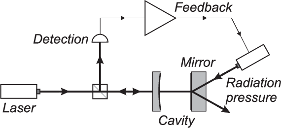
The electromagnetic field in the high-finesse cavity is described by a single harmonic mode characterized by annihilation and creation operators and . To determine the input-output relations for the fluctuations we linearize the evolution equations around the steady state of the system[30]. For a resonant cavity the fluctuations , and for the complex amplitudes at frequency of the incident, intracavity and reflected fields are related by
| (1a) | |||||
| (1b) | |||||
| where the Fourier transform of the time-dependent operator is defined as | |||||
| (2) |
Equation (1a) determines the dynamics of the intracavity field. is the round trip time of the cavity, is its damping rate (for a lossless cavity, and are respectively the reflection and transmission of the input mirror, with ). The second equation is the input-output relation for the fields. These equations are the usual ones for a single-ended cavity, with an extra term in eq. (1a) which couples the intracavity field to the mirror position . Neglecting any retardation effect[31] a displacement of the mirror induces a phase shift for the intracavity field proportional to the change of the optical path followed by the light beam. The optomechanical coefficient is given by[32]
| (3) |
where is the field wavevector and is the mean intracavity field.
The input field operators and obey the free fields commutation relations
| (4a) | |||||
| (4b) | |||||
| Since a resonant cavity does not introduce any phase shift between the incident, intracavity, and output mean fields, the complex amplitudes of these fields can be simultaneously taken real. Amplitude and phase quadratures and of the field then correspond to the real and imaginary parts of the operator , | |||||
| (5a) | |||||
| (5b) | |||||
| Assuming the incident field to be in a coherent state, quantum fluctuations of the two input quadratures and are characterized by | |||||
| (6a) | |||||
| (6b) | |||||
| where the correlation functions are defined from the quantum average of the symmetrized product of operators and , | |||||
| (7) |
We now give the fundamental equations for the mirror motion. We assume that the mechanical properties of the mirror can be described as a single harmonic oscillator. Experimentally, mirror motion may result from the excitation of many internal and external acoustic modes. The description as a single oscillator is however a good approximation when frequencies are limited to a small bandwidth around one mechanical resonance, by using for example a bandpass filter either in the detection or in the feedback loop [9].
We describe the mirror motion by the Fourier transform at frequency of the mirror velocity,
| (8) |
In the framework of linear response theory[33], the velocity linearly depends on applied forces which correspond to an external force , a fluctuating force associated with damping and describing the coupling with a thermal bath, and the radiation pressure of the intracavity field,
| (9) |
where is the mechanical impedance of the mirror. For a harmonic oscillator of mass , resonance frequency and mechanical damping , this impedance has the simple form,
| (10) |
Note that we have assumed for simplicity that the mechanical oscillator is viscously damped, that is is independent of frequency. This damping coefficient is related to the mechanical quality factor by
| (11) |
Last term in eq. (9) represents the optomechanical coupling between the mirror and the intensity of light in the cavity. It corresponds to quantum fluctuations of radiation pressure[34]. In the linearized approach this non-linear coupling reduces to a term proportional to the amplitude quadrature of the intracavity field [32]. The optomechanical coefficient is the same as in eq. (1a).
Quantum and thermal fluctuations associated with the damping can be deduced from fluctuation-dissipation theorem[26] and appear in eq. (9) as an additional term proportional to an input field . This field is the quantum analog to the usual Langevin force associated with thermal fluctuations for a damped mechanical oscillator coupled to a thermal bath at high temperature. It obeys the following commutation relation,
| (12) |
where denotes the sign of the frequency . When the mechanical bath is in a thermal state at temperature , the correlation function of the input field is equal to[26, 11]
| (13) |
where is the Boltzman constant.
For a free mechanical oscillator the only remaining force in eq. (9) is the input field and the correlation function of the mirror velocity is given by
| (14) |
Assuming the quality factor large compared to , the width of the resonance is much smaller than its resonance frequency . We can then assume that the spectrum of the fluctuating force associated with the damping corresponds to a white noise and we replace by in the right part of this equation. The velocity spectrum has the usual lorentzian shape corresponding to a mechanical oscillator in thermal equilibrium at an effective temperature defined as
| (15) | |||||
| (16) |
At high temperature () we find as expected that is equal to . The oscillator temperature however decreases with the bath temperature and tends at low temperature towards a limit equal to . This limit is associated with the zero-point quantum fluctuations of the mechanical oscillator. may be written as,
| (17) |
where is the number of thermal phonons. It is equal to at high temperature and reduces to at low temperature. The term in eq. (17) represents the energy of quantum zero-point fluctuations.
Note that the oscillator temperature is also related to the variance of the velocity (equal to the integral of ) by the equipartition theorem,
| (18) |
III Detection and cold damping
We now describe the measurement and the feedback loop. In presence of the intracavity radiation pressure and of an external force, the mirror velocity can be written from eqs. (1a) and (9) as a function of the input mechanical and optical fields,
| (19) |
This equation clearly shows the two fundamental noise sources for the mirror motion, corresponding to the coupling to the external bath (second term), and to the back action of the measurement (last term).
From eqs. (1) ouput fields can be related to input fields and to mirror velocity,
| (20a) | |||||
| (20b) | |||||
| The first equation shows that the reflected amplitude fluctuations are obtained from the incident ones by a simple phase shift. As expected for a resonant cavity, amplitude fluctuations are not coupled to the mirror motion. On the contrary the phase of the reflected beam depends on the cavity length and a measurement of the phase quadrature provides information about the mirror motion. The result of the measurement can be described by an estimator of the velocity, which is proportional to and which appears as the sum of and of some measurement noise, | |||||
| (21) | |||||
The sensitivity of the velocity measurement is limited by the phase noise of the incoming beam. The added noise in eq. (21) is proportional to and inversely proportional to the mean intracavity amplitude (eq. 3). As a consequence the sensitivity is increased when cavity finesse or light power are increased. One can also note a frequency filtering by the cavity, the sensitivity being reduced for frequencies larger than the cavity bandwidth .
We apply a feedback force on the mirror proportional to the result of the measurement, that is to the velocity estimator ,
| (22) |
where is an impedance which characterizes the transfer function of the feedback loop. The measurement noise as well as the back action noise are already present in our analysis. Other noise sources may be added to the feedback force, such as the quantum fluctuations of the radiation pressure due to the auxiliary laser beam used for feedback control, the electronic noise of the feedback loop, or the quantum efficiency of the detection. As it is well known in high sensitivity measurement, the dominant noise sources are those associated with the first stage of detection[35]. This result also holds for a quantum analysis of noise in presence of feedback [11, 29]. As a consequence we neglect in the following these extra noise sources.
The velocity in presence of feedback can be deduced from eq. (19). One gets
| (23) | |||||
The main effect of feedback is to change the mechanical impedance of the mirror which becomes the sum of the free mirror impedance and of the servocontrol impedance,
| (24) |
The feedback loop also adds noise to the mirror (last term in eq. 23). It corresponds to a contamination noise introduced by the feedback mechanism and proportional to the measurement noise of the velocity estimator. As a consequence there are two different noise sources associated with light and corresponding to the back action and measurement noises (two last terms in eq. 23).
The general expression of the velocity noise spectrum (without any assumption on incident field fluctuations) is given by
| (25) | |||||
Let us first examine the effect of feedback when quantum noises can be neglected as compared to thermal noise. To obtain a cold damping mechanism, the feedback force must correspond to a viscous force, that is the feedback impedance must be real (, ). In this case, the feedback loop changes the mechanical impedance by adding a damping to the mechanical damping . Neglecting the quantum noise of light (three last terms in eq. 25), one finds that the velocity noise spectrum has the same expression as for a free mechanical oscillator in thermal equilibrium (eqs. 13 and 14), except for the modification of the mechanical impedance. In other words the feedback loop changes the damping of the mirror without adding any noise. In this classical analysis of cold damping, the mirror appears to be in a thermal equilibrium at an effective temperature given by,
| (26) |
where the feedback gain is defined as
| (27) |
This result shows that the mirror is cooled at an effective temperature inversely proportional to the gain. It confirms the absence of classical limits for displacement noise reduction with cold damping[18].
Although the main properties of the cold damping mechanism are properly described here, one gets some inconsistency for large gains since the effective temperature can decrease down to 0 and it is not limited to the zero-point effective temperature corresponding to a mechanical oscillator at a null temperature (see eq. 16 and discussion thereafter). This is of course due to the fact that we have neglected all quantum noises. We study in the following how this result is modified by taking into account these noises.
IV Noise reduction at resonance
We study in this section the maximum noise reduction that can be obtained at the resonance frequency when the measurement and feedback parameters are optimized. For this purpose, we assume that the feedback corresponds to a cold damping mechanism, that is the feedback impedance is real ().
The expression of the velocity noise spectrum (eq. 25) can be simplified for a mechanical reservoir in a thermal state and for light in a coherent state. In this case the incident field noises are given by eqs. (6) and (13). We assume as in section II that the fluctuating incident force associated with mechanical damping has a white noise spectrum. We furthermore assume that the cavity bandwidth is large compared to the mechanical resonance frequency so that we can neglect the cavity filtering appearing in eq. (25). One then gets,
| (28) |
The resulting noise spectrum corresponds to the response of the mirror to the sum of thermal, back action, and measurement noises. The mechanical impedance which characterizes this response takes into account the presence of feedback.
At resonance, the mechanical impedance takes the simple form,
| (29) |
From eqs. (28) and (29) one can easily show that arbitrarily small values of the velocity noise at resonance can be reached by a proper choice of the optomechanical coefficient and of the feedback gain . Let us define an optomechanical parameter by
| (30) |
takes into account the light intensity via , the cavity finesse via , and the mechanical response of the mirror. This parameter can be made much larger than for a high-finesse cavity, high incident power, and high mechanical quality factor. is actually equal to where is the phase-shift of the intracavity field due to the mean radiation pressure. can be of the same order as for realistic experimental parameters[36].
The velocity noise at resonance is then given by,
| (31) |
where is the number of thermal phonons (eq. 17). The velocity noise is now normalized to the noise of the free oscillator at zero temperature (see eqs. 15 and 17). Both mechanical noise (term in eq. 31) and radiation pressure effects (term ) are reduced by the feedback loop. In other words, the mirror motion induced by the quantum fluctuations of radiation pressure is controlled in the same way as the brownian motion. For very large gains , both noises vanish and the resulting velocity noise is only due to the phase noise added by the measurement (last term in eq. 31). This last noise can also be made small by increasing the sensitivity of the measurement.
Taking , , and , all three terms are small compared to and the velocity noise of the cooled mirror becomes smaller than the noise of the free mirror at zero temperature,
| (32) |
As pointed in [37] a quantum treatment introduces extra noise sources that were absent in a classical analysis. Our results however show that as in the classical case there is no limit on the noise suppression.
It may appear surprising that the velocity noise at resonance can be made arbitrarily small. We remind however that cold damping modifies the dynamics of the oscillator. As a consequence the reduction of velocity noise is made at the expense of a widening of the mechanical resonance. The result is fully consistent with quantum mechanics since the velocity noise is larger than the value corresponding to the zero-point fluctuations of a damped oscillator with the same mechanical response. In next section we analyze more precisely the limits due to quantum noise by studying parameters that depend on noise over all frequencies such as the variance of the velocity or the effective temperature.
V Effective temperature
In presence of feedback the width of the resonance becomes . If we assume that this width stays smaller than the resonance frequency , that is if the gain is smaller than the quality factor , one can neglect the frequency dependence of the last term in eq. (28) and the velocity noise spectrum of the cooled mirror at any frequency can be written,
| (33) |
where the number of thermal phonons and the optomechanical parameter are defined in eqs. (17) and (30). The resulting noise spectrum is shown in figure 2 for different values of the feedback gain . The reduction and widening of the resonance are clearly visible.

For very large gains, the total impedance is proportional to and the noise spectrum is limited by the phase noise in the measurement (last term in eq. 33). In other words, the feedback works in such a way that its error signal, equal to the velocity estimator , goes to . The mirror velocity then reproduces the measurement noise of the estimator (see eq. 21).
Since the right part in eq. (33) is independent of frequency, the noise spectrum has always a lorentzian shape. The cooled mirror is thus equivalent to a harmonic oscillator of resonance frequency , damping , in thermal equilibrium at an effective temperature . This temperature can be determined either from the calculation of the variance as the integral of the noise spectrum and from the equipartition theorem (eq. 18), or by identifying the noise spectrum with the one of a free oscillator (eq. 15), taking into account the fact that the damping is increased by a factor . One then gets
| (34) |
The effective temperature of the cooled mirror is plotted in figure 3 as a function of the optomechanical coefficient , for different values of the gain and for an initial number of thermal phonons equal to . Efficient reduction of temperature can be achieved as soon as is larger than (curves c and d). The effective temperature is then determined by quantum noise. As in usual optical measurements[19, 20], phase noise of the measurement is dominant for low values of (term in eq. 34), and back action of radiation pressure is dominant for high (term in eq. 34). A quantum limit is reached for a precise value of which corresponds to the case where both noises are equal,
| (35) |
The minimum effective temperature is then,
| (36) |
We have thus found that for a given value of , there exists a limit for the effective temperature of the mirror. This limit evolves from the initial temperature for no gain, down to for an infinite gain (dashed curve in figure 3). This minimum corresponds to the effective temperature of a free harmonic oscillator coupled to a thermal bath at zero temperature (eq. 16).

Comparison between the cases of a cold damped mirror (eq. 36) and a free mirror (eq. 17) shows that the number of thermal phonons is reduced by a factor . This is the same reduction than with classical cold damping (eq. 26). On the contrary the quantum part (term ) remains unchanged. One can then define an effective number of thermal phonons in presence of feedback as,
| (37) |
The minimum number of thermal phonons is reached for and is inversely proportional to the gain,
| (38) |
This equation is the quantum generalization of the classical behavior of cold damping (eq. 26).
VI Quantum limits of cold damping
We revisit now the results obtained in previous sections within the framework of a general analysis of the noise added by a feedback mechanism. We will show that a minimum noise is imposed by quantum mechanics and that the cold damped mirror reaches this limit.
When a quantum system is coupled to a thermal bath, the quantum fluctuations-dissipation theorem provides a relation between the commutator of the force and the noise added by the coupling. A mean to obtain this relation is to analyze the unitarity of the input-output relations of the system. This kind of analysis also holds for active systems and provides lower bounds to the noise associated with amplifying devices[38, 39, 40].
This kind of analysis may be used to study the noise associated to a linear feedback. Let us consider a system characterized by a velocity and an impedance which is linearly fed back by a force applied with an impedance . Equations of the system can be written as the general relations,
| (39a) | |||||
| (39b) | |||||
| where is the input field associated with the free system. To preserve the commutation relations one has to introduce a force in eq. (39b) which appears as a noise term for the feedback force. To write the input-output transformation one has also to introduce an output field defined in the same way as the output light field for an optical system[11], | |||||
| (40) |
The output field is a free field which can be related to the incident fields and from eqs. (39). One gets,
| (41) |
where is the impedance in presence of feedback (eq. 24).
The unitarity of input-output transformations implies that commutators of the output field and of the input field are identical (eq. 12). As a consequence one gets from eq. (41) the commutator of the noise added by feedback,
| (42) |
This commutator implies a Heisenberg inequality on the correlation function of the force ,
| (43) |
This feedback noise has of course important consequences for the resulting noise spectrum of the system. The correlation function in presence of feedback can be calculated from eqs. (39) and one gets,
| (44) |
As in previous sections we assume that the total impedance is characterized by a width of the resonance much smaller than its resonance frequency . We can then replace by in the right part of eq. (44). The servocontrolled system is found to have the same velocity noise spectrum than an oscillator with an impedance , in thermal equilibrium at an effective temperature given by
| (45) |
where is the effective noise temperature of the feedback force defined as,
| (46) |
The effective temperature of the servocontrolled system is the average of the temperatures of the free system and of the feedback noise, weighted by the corresponding damping coefficients.
If the feedback noise corresponds to a coupling with a thermal bath at the initial temperature (), one finds that the feedback loop does not change the temperature. The servocontrol modifies the impedance of the system without any cooling effect. In this case it is equivalent to a modification of the impedance by passive means.
Quantum mechanics does not however prevent to use a feedback loop which has a lower noise temperature. With active elements or in presence of frequency transfer[11], the noise temperature is not the physical temperature of the device but it is determined by the physical process coming into play. The effective temperature of the servocontrolled system can therefore be reduced, down to a limit imposed on feedback noise by the Heisenberg inequality (eq. 43),
| (47) |
In this situation, the whole detection and feedback system acts on the oscillator as a coupling with a thermal reservoir at an effective temperature lower than .
We analyze now the performance of the optomechanical cold damping in light of these limits. The added force can be deduced from eq. (23),
| (48) |
It can be checked that this force verifies the required commutation relation (eq. 42). From eqs. (19) and (20), it is even possible to write input-output relations for all the fields (mechanical field , light fields and ) and to verify the global unitarity of the whole transformation.
Let us first examine the case of a dissipative feedback corresponding to the cold damping situation (, coherent incident field, and cavity bandwidth much larger than the mechanical resonance frequency). The noise spectrum of the added force can be derived from eq. (48) and leads to the feedback noise temperature,
| (49) |
where the feedback gain and the optomechanical parameter have been defined in eqs. (27) and (30). The feedback noise temperature obviously satisfies the Heisenberg inequality (eq. 47) and reaches its minimum value when is equal to . This equation sheds a new light on the results of previous section. The effect of cold damping can be interpreted in this case as a coupling with a thermal reservoir at zero temperature.
Let us finally examine a more general situation for which the incident field can be in a squeezed state and the feedback impedance can have a non zero reactive part. In this case, the added noise derived from eq. (48) leads to a feedback noise temperature,
| (50) | |||||
where the gain is now defined as .
With light fluctuations corresponding to a coherent state, the intensity-phase correlations are zero and the minimal temperature, reached for , is equal to
| (51) |
If the reactive part of the feedback impedance is not zero, the effective temperature is larger than the minimum imposed by the Heisenberg inequality (eq. 47).
It is however possible to reach the optimum value with an incident squeezed state, where intensity and phase noises are correlated. Correlation functions of the incident field must be equal to
| (52a) | |||||
| (52b) | |||||
| (52c) | |||||
| Note that this state is a minimum state for the generalized Heisenberg inequality of the field[41], | |||||
| (53) |
Two situations are of particular interest. First, we still consider a cold damping mechanism (), but with an incident field which phase is squeezed by a factor ,
| (54) |
In this case, the zero noise temperature can be reached for a smaller optomechanical parameter , equal to . The effect is actually similar to the one that can be obtained in interferometric measurements[19]. The incident phase-squeezed state reduces the phase noise of the measurement, at the expense of an increase of the back action noise due to radiation pressure. As a consequence the standard quantum limit can be reached for a lower light power. For the cold damped mirror, this corresponds to a translation towards the left of the curves in figure 3.
In the second situation we consider that the reactive part of the feedback impedance is not zero. This may be wanted to change both the mechanical damping and the mechanical resonance position. A squeezed state with intensity-phase correlations is required to reach the minimum of added noise. For a value of the optomechanical parameter equal to , the squeezed quadrature has to be rotated by an angle of with respect to phase and intensity quadratures, and the squeezing factor must be equal to
| (55) |
The optimum noise is then reached for a finite squeezing factor, except for a purely reactive feedback (). In this case, the zero noise temperature is only a limit corresponding to an infinite squeezing.
The zero noise temperature can also be reached for arbitrary values of the optomechanical parameter (), by a proper choice of the squeezed quadrature and of the squeezing factor (see eqs. 52). It is in particular possible to reduce the optomechanical parameter at the expense of an increase of the squeezing factor.
VII Conclusion
The whole detection and feedback system used in cold damping techniques allows to simulate a thermal reservoir at zero temperature. It is then possible in principle to cool the oscillator down to its zero-point quantum fluctuations.
The optomechanical system is well adapted to cold damping and can be optimized to reach the limits imposed by quantum mechanics. In this system, the performance limits are due to the Heisenberg inequality on the intensity and phase of the detection beam. They correspond to the general limits of cold damping.
As it is the case for classical cold damping, thermal fluctuations are reduced by a factor inversely proportional to the feedback gain. Zero-point quantum fluctuations of the oscillator are however left unchanged by feedback and provide a limit to the reduction of the oscillator energy.
Reduction of the effective temperature is accompanied by an increase of the effective damping of the mirror. Although the energy is limited by zero-point fluctuations, we have shown that arbitrarily large noise reduction can be achieved at a given frequency.
One may finally wonder how these limits can be experimentally observed. The residual brownian motion of the cold damped mirror can be measured by a second displacement sensor, or equivalently by using a second independent light beam in the high-finesse cavity. One has however to take into account the quantum noises associated with this second beam. As for the first intracavity beam, one finds that radiation pressure effects of the second beam are controlled by the feedback loop so that the sensitivity of the measurement is only limited by the phase noise, which can be made arbitrarily small by increasing the light power.
References
- [1] C. Bradaschia et al., Nucl. Instrum. Methods Phys. Res. A 289, 518 (1990)
- [2] A. Abramovici et al., Science 256, 325 (1992)
- [3] A. Einstein, Annalen der Physik 17, 549 (1905)
- [4] H. Nyquist, Phys. Rev. 32, 110 (1928)
- [5] E.M. Lifshitz and L.P. Pitaevskii, Landau and Lifshitz, Course of Theoretical Physics, Statistical Physics Part 2 (Butterworth-Heinemann, 1980), ch. 8
- [6] S. Rowan et al., Phys. Lett. A 265, 5 (2000)
- [7] T. Uchimaya et al., Phys. Lett. A 242, 211 (1998)
- [8] S. Mancini, D. Vitali and P. Tombesi, Phys. Rev. Lett. 80, 688 (1998)
- [9] P.F. Cohadon, A. Heidmann and M. Pinard, Phys. Rev. Lett. 83, 3174 (1999)
- [10] J.M.W. Milatz and J.J. Van Zolingen, Physica XIX, 181 (1953); J.M.W. Milatz, J.J. Van Zolingen and B.B. Van Iperen, Physica XIX, 195 (1953)
- [11] F. Grassia, J.-M. Courty, S. Reynaud and P. Touboul, Eur. Phys. J. D 8, 101 (2000), arXiv: quant-ph/9904073
- [12] A. Bernard and P. Touboul, The GRADIO accelerometer: design and development status, Proc. ESA-NASA Workshop on the Solid Earth Mission ARISTOTELES, Anacapri, Italy 1991
- [13] P. Touboul et al., Continuation of the GRADIO accelerometer predevelopment, ONERA Final Report 51/6114PY, 62/6114PY ESTEC Contract (1992, 1993)
- [14] M. Pinard, P.F. Cohadon, T. Briant and A. Heidmann, Phys. Rev. A 63, 013808 (2000)
- [15] Y. Hadjar, P.F. Cohadon, C.G. Aminoff, M. Pinard and A. Heidmann, Europhys. Lett. 47, 545 (1999)
- [16] I. Tittonen et al., Phys. Rev. A 59, 1038 (1999)
- [17] C.W. McCombie, Rep. Prog. Phys. 16, 226 (1953)
- [18] R. Ritter and G. Gillies, Phys. Rev. A 31, 995 (1985)
- [19] C.M. Caves, Phys. Rev. D 23, 1693 (1981)
- [20] V.B. Braginsky and F.Ya. Khalili, Quantum Measurement (Cambridge, University Press, 1992)
- [21] M.T. Jaekel and S. Reynaud, Europhys. Lett. 13, 301 (1990)
- [22] H.A. Haus and Y. Yamamoto, Phys. Rev. A 34, 270 (1986)
- [23] H.M. Wiseman, Phys. Rev. A 49, 2133 (1994)
- [24] H.M. Wiseman, Phys. Rev. A 51, 2459 (1995)
- [25] B.C. Buchler et al., Opt. Lett. 24, 259 (1999)
- [26] H.B. Callen and T.A. Welton, Phys. Rev. 83, 34 (1951)
- [27] B. Yurke and J.S. Denker, Phys. Rev. A 29, 1419 (1984)
- [28] C.W. Gardiner, IBM J. Res. Dev. 32, 127 (1988)
- [29] J.-M. Courty, F. Grassia and S. Reynaud, in Noise, Oscillators and algebraic Randomness, Springer Lecture Notes (Springer, Berlin-Heidelberg, 2000), p. 71
- [30] S. Reynaud and A. Heidmann, Opt. Commun. 71, 209 (1989); S. Reynaud, Ann. Physique 15, 63 (1990)
- [31] P. Tourrenc and N. Deruelle, Ann. Physique 10, 241 (1985)
- [32] M. Pinard, Y. Hadjar and A. Heidmann, Eur. Phys. J. D 7, 107 (1999)
- [33] E.M. Lifshitz and L.P. Pitaevskii, Landau and Lifshitz, Course of Theoretical Physics, Statistical Physics Part 2 (Butterworth-Heinemann, 1980), ch. 12
- [34] Quantum Optics, Experimental Gravitation and Measurement Theory, edited by P. Meystre and M.O. Scully (Plenum, 1983)
- [35] J.-M. Courty, F. Grassia and S. Reynaud, arXiv: quant-ph/0110022
- [36] A. Heidmann, Y. Hadjar and M. Pinard, Appl. Phys. B 64, 173 (1997)
- [37] D. Vitali, S. Mancini and P. Tombesi, Phys. Rev. A 64, 051401(R) (2001)
- [38] H.A. Haus and J.A. Mullen, Phys. Rev. 128, 2407 (1962)
- [39] C.M. Caves, Phys. Rev. D 26, 1817 (1982)
- [40] J.-M. Courty, F. Grassia and S. Reynaud, Europhys. Lett. 46, 31 (1999),arXiv: quant-ph/9811062
- [41] S. Reynaud, A. Heidmann, E. Giacobino and C. Fabre, in Progress in Optics XXX, ed. by E. Wolf (North-Holland, Amsterdam, 1992), p. 1