Rocking and rolling: a can that appears to rock might actually rollPreprint: APS/123-QED
Abstract
A beer bottle or soda can on a table, when slightly tipped and released, falls to an upright position and then rocks up to a somewhat opposite tilt. Superficially this rocking motion involves a collision when the flat circular base of the container slaps the table before rocking up to the opposite tilt. A keen eye notices that the after-slap rising tilt is not generally just diametrically opposite the initial tilt but is veered to one side or the other. Cushman and Duistermaat (2006) recently noticed such veering when a flat disk with rolling boundary conditions is dropped nearly flat. Here, we generalize these rolling disk results to arbitrary axi-symmetric bodies and to frictionless sliding. More specifically, we study motions that almost but do not quite involve a face-down collision of the round container’s bottom with the table-top. These motions involve a sudden rapid motion of the contact point around the circular base. Surprisingly, like for the rolling disk, the net angle of motion of this contact point is nearly independent of initial conditions. This angle of turn depends simply on the geometry and mass distribution but not on the moment of inertia about the symmetry axis. We derive simple asymptotic formulas for this “angle of turn” of the contact point and check the result with numerics and with simple experiments. For tall containers (height much bigger than radius) the angle of turn is just over and the sudden rolling motion superficially appears as a nearly symmetric collision leading to leaning on an almost diametrically opposite point on the bottom rim.
pacs
45.20.dc,45.40.-fI Introduction
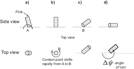
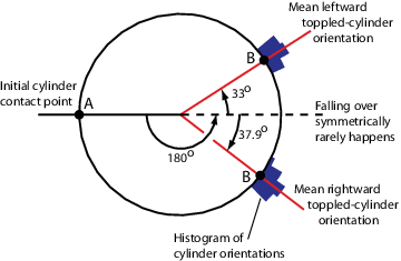
After a meal or a drink, fidgety people sometimes play with the available props, such as empty glasses, bottles, and soda cans. These containers are all nearly axi-symmetric objects with round bottoms. A natural form of play is to roll these containers on their circular bottoms. When a slightly tipped container (Fig. 1) is let go, sometimes one sees it fall upright, make a slight banging sound, and then tip up again at another angle, then fall back upright again, and so on for a few rocking oscillations. Because these oscillations usually damp quickly its easy to miss the details of the motions. To aid the eye, instead of just letting go of the slightly tilted container, you can flick its top forward with the fingers. This provides an initial righting angular velocity along the axis about which the container was initially tipped (too large an angular velocity will cause the container to lift off the table as it pivots over). The tipping container, as before, falls to a vertical configuration, at which time its bottom circular face bangs on the table. After this bang, the container tips up onto the other side and maybe falls over. When this experiment is performed with a container that is not too tall and too thin, you can see that the container does not fall exactly onto the diametrically opposite side of the bottom rim. That is, point A on the bottom of the container that initially contacted the table and the new contact point B, that the container rocks up onto, are not exactly 180 degrees apart. This experiment (video available online 11 1 A video of this experiment is available from the authors’ web pages and as a supplementary EPAPS file from the APS website.) is shown schematically in Fig. 2. Fig. 3 shows a histogram of one particular container’s orientations after we repeatedly flicked it. The distribution is strongly bimodal with no symmetric falls over many repeated trials.

Note the apparent symmetry breaking with . Is this deviation from symmetric rocking due to imperfect hand release? Here we show that the breaking of apparent symmetry is consistent with the simplest deterministic theories, namely smooth rigid body dynamics. We derive formulas for the “angle of turn”, for both the perfect-rolling and for the frictionless-sliding cases given infinitesimal symmetry breaking in the initial conditions. The results here generalize some of the nearly-falling-flat results of Cushman and Duistermaat Cushman and Duistermaat 2006; they considered the special case of the pure-rolling of flat disks.
II Candidate theories for symmetry breaking
If the table was perfectly planar and horizontal, the container’s bottom was perfectly circular, and the container was perfectly axisymmetric, then an initial condition with a purely righting angular velocity would result in a collision in which, just as the container becomes vertical, all points on the container’s bottom slap the table-top simultaneously. The consequence of such a rigid-container collision is not computable since algebraic rigid-body collision laws are not well-defined for simultaneous multi-point collisions; for example, the order of the impulse locations is then ill-defined Ivanov 1995; Goyal et al. 1998; Chatterjee and Ruina 1998; Ruina et al. 2005. Basing the rocking outcome on such a perfect flat collision would be basing the outcome on details of the deformation, that is, leaving the world of rigid-object mechanics.
Geometric perturbations to the circular rim can similarly lead to two-point collisions, where both points of contact are now on the rim. The second point of contact could be diametrically opposite to the first point, or anywhere else on the rim. We could then compute the consequences of, say, a plastic collision at the new point of contact. However, the consequences of the collision would depend on the location of the geometric imperfection. For a given collision point, such a theory could predict the energy dissipation at the collision. But such a theory cannot be useful in predicting a systematic breaking of symmetry as seen in Fig. 3. For any given imperfection, the motion is deterministic and depends on the location of the impection, and there is no reason to expect that the location of the imperfection would have a distribution similar to that in Fig. 3.
Assuming a perfectly flat rigid bottom, the circle-slapping-ground simultaneous collision is essentially impossible. After all, the container is being launched by imperfect human hands that cannot provide any exact initial conditions. Accounting for various symmetries in the problem, the set of all motions of a container rolling without slip is three dimensional; the space of solutions could be parameterized by, say, the minimum tip angle , the yaw rate at that position, and the rolling rate at that position. The set of solutions that leads to a face-down collision can be characterized with only two parameters, a set with co-dimension one O’Reilly 1996; Borisov and Mamaev 2002; Cushman and Duistermaat 2006. So, small generic perturbations of a “collisional” initial condition result, with probability 1, in a non-collisional motion described by the smooth dynamics of the container rolling or sliding on its circular bottom rim.
The rest of this paper is about the near-collisional motions. We will see that these near-collisional motions involve rapid rolling or sliding of the container on its bottom rim, so that the contact point appears to have switched by a finite angle that is greater than 180 degrees. For this analysis, we assume a geometrically perfect container (axisymmetric) and table (flat).
III Dynamics of Rocking by rolling
Consider a container with mass , bottom radius 22 2 Only the bottom radius is important. The container need not be a constant-radius cylinder., and the center of mass at a height from the bottom. The moment of inertia is about it’s symmetry axis and is about any axis passing through the center of mass and perpendicular to the symmetry axis. For the disk of Cushman and Duistermaat 2006, and . In our case, and .
The center of mass of the container is at in an inertial frame -- at rest with respect to the table. The reference orientation of the container is vertical as shown in Fig. 4a. Any other orientation of the container can be obtained from the reference orientation by a sequence of three rotations, defining corresponding Euler angles as illustrated in Fig. 4. The first rotation (‘yaw’ or ‘steer’) is about by an angle . This rotation also transforms the inertial coordinate axes to --. The second rotation (‘pitch’ or ‘tilt’) by an angle about the axis results in the -- frame and determines the orientation of the container up to a rotation about the body-fixed symmetry axis ( axis). The angular velocity of the container in the rotating -- frame is therefore entirely along the symmetry axis and this relative angular velocity magnitude is denoted by .

We will mostly consider two simple extremes for the frictional interaction between the table and the container’s bottom, namely, sliding without friction and rolling without slip.
For pure rolling, the Euler angles and their first and second time derivatives determine the center-of-mass position (relative to the contact point), the center-of-mass velocity and acceleration, as well as the container’s angular velocity and angular acceleration. The three second order ODEs that determine the evolution of the orientation , , and follow from angular momentum balance about the contact point:
| (1) |
where
| (2) | |||||
These equations are derived in Appendix A. Because the center-of-mass velocity is determined by the Euler angles and their rates, once these are known the center of mass position can be found by integration.
For the frictionless sliding of the cylinder on its circular bottom, the equations of motion are also given by Eq. 1 but with
| (3) | |||||
When the table is frictionless, the horizontal velocity of the center of mass is a constant, so that the horizontal position is independent of the orientation. The vertical position of the center of mass is simply given by . Without loss of generality the center-of-mass can be taken as on a fixed vertical line.
Our initial discovery of the phenomenon described here was found in numerical simulations of the equations above. We used an adaptive time-step, stiff integrator because the solutions of interest have vastly changing time-scales. The singularity of the Euler-angle description in the near-vertical configuration also contributes to the stiffness of the equations.

For simplicity of presentation, we first describe in detail the results of integration when the container does not slip with respect to the table. First, we integrate the equations with initial conditions that lead exactly to a face-down collision , , and say, . As would be expected, the container lands in a manner that all of its bottom face simultaneously reaches the horizontal table-top. Up to this time the motion of the container is identical to that of an inverted pendulum hinged at the contact point A. The integration becomes physically meaningless at that collision point.
In the vicinity of these collisional motions, the solutions of the equations of motion here do not have smooth dependence of solutions on initial conditions. To obtain a near-collisional motion, we set , , , and , where is a small quantity. The results of the integration are shown in Fig. 5. The plot of suggests a motion in which the container’s bottom face periodically comes close to touching the table (), but then gets “repelled” by the floor as if by an elastic collision, so that the container rocks down and up periodically, ad infinitum, without losing any energy, as expected from this dissipation-free system. We notice that when , changes almost discontinuously. Also, when is close to zero, both and blow up to very large values, resulting in almost discontinuous changes in the corresponding angles and .
Note that we are simply simulating the apparently smooth differential equations, and not applying an algebraic transition rule for a collision. As goes to zero, the angle rates and grow without bound, but the magnitude of the angular velocity vector is always bounded, as it must be since energy remains a constant throughout the motion. In particular, while the angle rates and are large, they are very close to being equal and opposite (, Fig. 5i).
Let us examine the consequences of a rapid finite change in when . The position of the contact point P on the ground relative to the center of mass is given by the following equations:
When and is not particularly close to any multiple of , the contact point position is given by
| (4) |
Given that do not change much during the brief near-collisional phase (because center of mass velocity is finite), we can see from Eq. 4 that a rapid continuous change in corresponds to a rapid continuous change in the contact point in a circle with the center . Thus the “angle of turn” AOB defined earlier is simply the change in . At the singular limit of a near-collisional motion arbitrarily close to a collisional motion, this continuous but steep change in approaches a step change – this is the “limiting angle of turn” and we denote this by .
We consider the near-collisional motions of the no-slip container that can be characterized as being the pasting-together of two qualitatively distinct motions of vastly different time-scales:
- 1.
inverted pendulum-like motion about an essentially fixed contact point when the tilt angle is large.
- 2.
rapid rolling of the container which accomplishes in infinitesimal time, a finite change in the contact point, and a sign-change in the tilt rate .
Note that the near-collisional motion for a container rolling without slip requires very high friction forces (for non-zero , see Fig. 5g). However, plotting the ratio of the required friction forces with the normal reaction, we find that only a finite coefficient of friction is required for preventing slip even in the collisional limit (Fig. 5h).
The other extreme of exactly zero friction is similar. Here, the horizontal component of the center of mass velocity may be taken to be zero. The near collisional motions for a container sliding without friction are again characterized as consisting of two qualitatively different phases:
- 1.
a tipping phase when is not too small, involving the container moving nearly in a vertical plane, the center of mass moving only vertically, and the contact point slipping without friction.
- 2.
a rapid sliding phase in which the sign of is reversed almost discontinuously, and the contact point moves by a finite angle in infinitesimal time.
The angle of turn for the frictionless case and the no-slip case are different in general (when ). In the next two sections, we derive the formulas for the angle of turn by taking into account the two-phase structure of the near-collisional motion.
IV Angle of turn for no-slip rolling
The rigid body dynamics of disks, containers, and similar objects with special symmetries, have been discussed at length by a number of authors, including distinguished mechanicians such as Chaplygin, Appell, and Korteweg. Their works include complete analytical characterizations of the solutions to the relevant equations of motion, typically involving non-elementary functions such as the hyper-geometric. Reasonable reviews of such literature can be found, for instance, in O’Reilly 1996 and Borisov and Mamaev 2002. We will not use these somewhat cumbersome general solutions but will analyze only the special near-collisional motion of interest to us.
The calculation below may be called, variously, a boundary layer calculation, a matched asymptotics calculation (but we are not interested in an explicit matching) or a singular perturbation calculation. Essentially, we take advantage of the presence of two dynamical regimes with vastly different time-scales, each regime simple to analyze by itself. The overall motion can be obtained approximately by suitably pasting together the small- and the large- solutions. But the angle of turn is entirely determined by the small- regime, as will be seen below.
First, consider Eq. 1 with in the limit of small , so that we can use and , and generally neglect terms of . We obtain
| (5) |
Now, considering Eq. 1 with in the limit of small , we obtain
| (6) |
Eqs. 5 and 6 are linear and homogeneous in , , and their time derivatives. So, positing a linear relation between and , we find that the following two equations are equivalent to Eqs. 5 and 6:
| (7) |
and
| (8) |
Note that Eq. 7 agrees with the results of the numerical simulation, as in Fig. 5i. Even though this equation was derived for small , this equation is approximately true at large as well if the initial conditions of the motion at large have and , as is the case for the near-collisional motions we consider.
Now consider Eq. 1 with and with .
| (10) |
Using Eq. 7 in Eq. 10 and ignoring higher order terms in , we obtain
| (11) |
Using Eq. 9 for in the above equation and neglecting the term (as it is a constant and therefore, much smaller than 1/ for small ), we get
| (12) | |||||
where
| (13) |
The general solution for the differential equation in , Eq. 12, can be written as
| (14) |
where is the lowest attained by the container before rising back up again, and is when this minimum is attained. Substituting this equation in Eq. 9, we obtain a simple equation for the evolution of when near the surface:
We can now compute the change in during a small time interval centered at .
From conservation of energy, we can show that , and therefore , must be (see Appendix B). Hence, as . Keeping a small constant as we let , thus approaching the collisional limit, gives us the following expression for .
| (15) | |||||
This is the limiting angle of turn when the container rocks by rolling without slip. Earlier numerical integrations agree quite well with this formula near the collisional limit, as they should.
V Angle of turn for frictionless sliding
We now briefly outline the procedure for deriving the angle of turn for the frictionless case. The procedure closely parallels that described for the no-slip case, except for small differences below. The frictionless equations Eq. 1 and Eq. 3 corresponding to simplifies to
| (16) |
Here, because the initial conditions satisfy and by assumption, as before. Using Eq. 16 in the frictionless equation Eq. 1 and Eq. 3 corresponding to , we have, after some simplifications:
| (17) |
where is a constant of integration, whose order is estimated in Appendix B. Substituting this into the frictionless equation and simplifying by neglecting all higher order terms, we eventually obtain
| (18) |
Using arguments identical to the pure-rolling case, this results in the following expression for the angle of turn,
| (19) |
for the frictionless limit.
VI An alternate heuristic small angle treatment
In this section, we derive the same angle of turn formulas (Eq. 15 and 19) without referring back to the complicated full dynamical equations. Rather, using heuristic reasoning, we directly derive equations of motion that apply at the small angle limit ().
We represent the lean of the cylinder by the vector with magnitude equal to and direction along the axis: . These quantities and are related to each other exactly like and , respectively, in traditional polar coordinates.
Neglecting any angular velocity component along , the angular velocity vector for the cylinder is given by . The rate of change of angular momentum about the center of mass G is given by:
| (20) | |||||
The angular momentum balance equation is then given by
| (21) |
where is the moment of all the external forces about G. depends on whether or not there is friction; so we treat the two cases in turn.
VI.1 Sliding without friction
The vertical position of the center of mass is . So . The vertical ground reaction is thus , neglecting gravity in comparison. The moment of this vertical force about the center of mass G is equal to in the direction . Substituting this along with Eq. 20 in the angular momentum balance equation Eq. 21, we have
This vector equation is identical to Eqs. 17 and 18 and therefore, lead to the same angle of turn (Eq. 19).
VI.2 Rolling without slip
The position of the center of mass G with respect to the point P′ on the cylinder in contact with ground is given by . The velocity of the center of mass G is given by . Using the no-slip constraint , we obtain after some simplifications, the acceleration of the center of mass to first order to be
| (22) |
The ground reaction force, which now includes a horizontal friction force as well, is simply , neglecting gravity. The moment of this ground reaction force about G is given by
Equating above to from Eq. 20 gives Eqs. 8 and 11 from the previous version of the derivation, therefore resulting in the same formula for the angle of turn (Eq. 15).
VII Quantitative comparisons
Firsly and most significantly, note that the limiting angle of turn does not depend on the initial conditions such as the initial tilt and tip velocity. This means that we do not have to control these accurately in an experiment. This also agrees with the relatively small variance in the histogram of Fig. 3, in which we did not control the initial conditions.
The histogram Fig. 3 was obtained using the cylindrical container shown in Fig. 1 with cm, cm, m2. Using these numbers in the angle of turn formulas gives an angle of turn of about 220 degrees for frictionless sliding and an angle of turn of degrees for rolling without slip. These angles of turn would manifest as a deviation of either degrees or degrees from falling over to exactly the diametrically opposite side. In the toppling experiment of Fig. 3, the container orientation was 33 degrees on average from 180 degrees in the leftward falls (suggesting an angle of turn of 213 degrees) and was about 37.9 degrees on average from 180 degrees in the rightward falls (suggesting angle of turn of 217.9 degrees). The standard deviations were respectively 3.9 and 4.5 degrees respectively. The experimental angle of turn seems better predicted by the asymptotic formula for frictionless sliding in this case. Although, neither the frictionless limit nor the no-slip limit is just right, both limits capture the many qualitative aspects of the motion quite well.
VIII Special limit: Tall thin containers
For tall thin cylinders with and , both equations for the angle of turn, Eq. 15 and Eq. 19, tend to radians. That is, very tall cylinders are predicted to have a smaller symmetry-breaking. This prediction agrees with the common experience that when we tip a tall-enough cylinder (something that looks more like a tall thin beer bottle) in a manner that its bottom surface nearly falls flat, the cylinder essentially rocks up on a contact point almost diametrically opposite to the initial contact point. Thus, this apparently almost-symmetric rocking is accomplished by a rapid asymmetric rolling or sliding of the container over roughly one half of its bottom rim! This result is basically independent of the container-table frictional properties.
IX Special limit: Disks
We may define a disk as a container with zero height: , a good approximation is the Euler’s disk Moffatt 2000. If the radius of gyration of a disk is , then and . Substituting these into the angle of turn formulas for the no-slip (Eq. 15) or the frictionless (Eq. 19) cases, we obtain the same angle of turn:
| (23) |
Indeed, numerical exploration with Eqs. 1-3, suitably modified for frictional slip and specialized to disks, shows no dependence of the angle of turn on the form of the friction law or the magnitude of the friction. This lack of dependence on friction could be anticipated from our small angle calculations for pure rolling cylinders, specialized to disks. In particular, we find that the acceleration of the center of mass for a pure rolling cylinder (Eq. 22) with is vertical in the small-angle limit, enabling the no-slip condition to be satisfied even without friction. Thus, the rolling solution is obtained with or without friction. For the special case of pure-rolling disks, Eq. 23 was found in Cushman and Duistermaat 2006.
A homogeneous disk has . The corresponding angle of turn is equal to , which is about 41 degrees more than a full rotation of the contact point. This prediction is easily confirmed in casual experimentation with metal caps of large-mouthed bottles or jars on sturdy tables – for such caps, we observe that the new contact point is invariably quite close to the old contact point.
A ring such as the rim of a bicycle wheel has . The corresponding angle of turn is equal to , which is about 48 degrees less than a full rotation of the contact point. Thus the apparent near-collisional behavior of a homogeneous disk and a ring will be superficially similar, even though the actual angles of turn differ by about degrees.
The angle of turn can be controlled by adjusting . For instance, between a ring and a disk is an object that appears to bounce straight back up the way it falls. And it is possible to increase the theoretical angle of turn without bound by choosing , a disk in which almost all the mass is concentrated at the center.
X Summary
Here we analyzed what happens when a cylinder or a disk rocks to an almost flat collision on its bottom surface. We found that the smallest deviation from a perfect face-down collision of a container’s bottom results in a rapid rolling and/or sliding motion in which the contact point moves through a finite angle in infinitesimal time. Calculations of this finite angle explain certain apparent symmetry breaking in experiments involving rocking or toppled containers.
In this system, the consequences of such a degenerate ‘collision’ are a discontinuous dependence on initial conditions (rolling left or rolling right depend on the smallest deviations in the initial conditions). Such discontinuous dependence on initial conditions or geometry is a generic feature of systems in the neighborhood of simultaneous collisions. Other examples include a pool break or the rolling polygon of Ruina et al. 2005.
Acknowledgements.
Thanks to Arend Schwab for comments on an early manuscript and Mont Hubbard for editorial comments. The alternate heuristic derivation of Section VI were informed by discussions with Anindya Chatterjee in the context of the Euler’s disk. MS was supported by Cornell University in the early stages of this work (2000). The work was also supported partly by NSF robotics (CISE-0413139) and FIBR (EF-0425878) grants.Appendix A Deriving equations of motion
The moment of inertia tensor of the cylinder about its center of mass is, in dyadic form,
| (24) |
The angular velocity of the cylinder is given by
| (25) |
The angular momentum about the center of mass is
The rate of change of angular momentum is given by the sum of two terms: 1) the rate of change relative to the rotating frame --, obtained by simply differentiating the components in Eq. , and 2) the rate of change due to the rotation of the -- frame with an angular velocity .
| (27) |
A.1 No-slip rolling
The point S on the cylinder in contact with the ground has zero velocity: , no slip. Using , the velocity of the center of mass is given by
| (28) | |||||
The acceleration of the center of mass is given by adding two terms: 1) acceleration relative to the rotating -- frame, obtained by differentiating the components in Eq. 28, and 2) an acceleration term due to the rotation of -- frame. We obtain
| (29) | |||||
The contact force is given by linear momentum balance:
| (30) |
Then, the moment of all the external forces about the center of mass is
| (31) | |||||
in which, upon simplification, we have
Equating and gives us the angular momentum balance equations of motion for no-slip rolling in Eqs. 1,2.
A.2 Frictionless sliding
No friction implies that the horizontal velocity of the center of mass G is a constant and can be set to zero by appropriate reference frame choice, without loss of generality. Further, noting that , we have, by differentiating twice:
As before, we compute the contact force as and compute the net moment about the center of mass as
Again, equating with the before gives us the required equations of motion Eqs. 1,3.
Appendix B Scaling of
B.1 No-slip rolling
We now establish that , used in obtaining Eq. 15. The total mechanical energy of the cylinder, a constant, is given by:
| (33) | |||||
in which P.E. is the potential energy. We consider this total energy at the time of lowest tip angle , , we have , , , and the potential energy P.E. . Making use of the usual small approximations (as used in the main text) and Eq. 7, namely , we find that
| (34) |
Because is a constant, we have or as claimed earlier.
B.2 Frictionless sliding
The total mechanical energy is now given by
| (35) | |||||
Again, using small approximations and considering the energy equation at , we obtain , using arguments identical to the no-slip rolling case.
References
- Ivanov (1995) A. P. Ivanov, Journal of Applied Mathematics and Mechanics 59, 887 (1995).
- Goyal et al. (1998) S. Goyal, J. M. Papadopoulos, and P. A. Sullivan, Journal of Dynamic Systems, Measurement, and Control 120, 83 (1998).
- Chatterjee and Ruina (1998) A. Chatterjee and A. Ruina, ASME Journal of Applied Mechanics 65, 939 (1998).
- Ruina et al. (2005) A. Ruina, J. E. A. Bertram, and M. Srinivasan, Journal of Theoretical Biology 237, 170 (2005).
- O’Reilly (1996) O. M. O’Reilly, Nonlinear Dynamics 10, 287 (1996).
- Borisov and Mamaev (2002) A. V. Borisov and I. S. Mamaev, Regular and Chaotic Dynamics 7, 177 (2002).
- Cushman and Duistermaat (2006) R. H. Cushman and J. J. Duistermaat, Regular and Chaotic Dynamics 11, 31 (2006).
- Moffatt (2000) H. K. Moffatt, Nature 404, 833 (2000).