Influence of lasers propagation delay on the sensitivity of atom interferometers
J. Le Gouët, P. Cheinet, J. Kim, D. Holleville, A. Clairon, A. Landragin, F. Pereira Dos Santos
LNE-SYRTE, CNRS UMR 8630
Observatoire de Paris, 61 av. de
l’Observatoire, 75014 Paris, France
E-mail : franck.pereira@obspm.fr
Abstract
In atom interferometers based on two photon transitions, the delay induced by the difference of the laser beams paths makes the interferometer sensitive to the fluctuations of the frequency of the lasers. We first study, in the general case, how the laser frequency noise affects the performance of the interferometer measurement. Our calculations are compared with the measurements performed on our cold atom gravimeter based on stimulated Raman transitions. We finally extend this study to the case of cold atom gradiometers.
1 Introduction
Atom interferometry allows to realize measurements in the fields of frequency metrology [1], inertial sensors [2, 3], tests of fundamental physics [4, 5, 6]. This technique is based on the splitting of an atomic wave function into separated wave packets. The difference in the quantum phases accumulated by the wave packets can be extracted from the interference pattern obtained when recombining them. Among the various types of coherent beam splitters developed for matter wave manipulation [7, 8, 9, 10, 11], two photon transitions have proven to be powerful tools for precise measurements. For instance, atom interferometers based on Bragg transitions [8] can be used for polarisability [12] and fundamental measurements [13]. Stimulated Raman transitions [14] allowed the development of high precision inertial sensors [15, 16, 17, 18], whose performances compete with state of the art instruments [19, 20].
In the case of interferometers based on two photon transitions, atomic wave packets are split and recombined with light pulses of a pair of counter-propagating laser beams, which couple long lived atomic states. The sensitivity of such interferometers arises from the large momentum transfer of counter-propagating photons. A propagation delay is unavoidable between the two counter-propagating beams at the position of the atoms, and we show here that this delay makes the interferometer measurement sensitive to the lasers frequency noise. Without losing generality, we detail this effect in the case of our gravimeter, based on stimulated Raman transitions. However, the formalism presented here can be applied to any type of interferometer where two photon transitions are used as beam splitters.
The sensitivity to inertial forces of such an interferometer arises from the imprinting of the phase difference between the lasers onto the atomic wave function [21]. As temporal fluctuations in this laser phase difference affect the measurement of the atomic phase, a high degree of phase coherence is required. This coherence can be obtained either by using two sidebands of a single phase modulated laser [2], or by locking the phase difference between two independent lasers [22, 23]. In both cases, the phase relation is well determined only at a specific position, where the laser is modulated or where the frequency difference is measured. Between this very position and the atoms, this phase difference will be affected by fluctuations of the respective paths of the two beams over the propagation distance. In most of the high sensitivity atom interferometers, the influence of path length variations is minimized by overlapping the two beams, and making them propagate as long as possible over the same path. The vibrations of any optical element shift the phase of each laser, but do not strongly disturb their phase difference as long as the lasers co-propagate, because their optical frequencies are very close. However, for the interferometer to be sensitive to inertial forces, the two beams (with wave vectors and ) have to be counter-propagating. The two overlapped beams are thus directed to the atoms and retro-reflected. Among the four beams actually sent onto the atoms, two will realize the interferometer pulses. As a consequence, the reflected beam is delayed with respect to the other one. The phase difference at the atoms position is then affected by the phase noise of the lasers, accumulated during this reflection delay.
In this article, we investigate both theoretically and experimentally the influence of the delay on the sensitivity of an atom interferometer. In the following section, we briefly describe our experimental setup. The transfer function of the interferometer phase noise with respect to the Raman laser frequency noise is derived in section 3, and compared with experimental measurements. In section 4, we demonstrate the sensitivity limitations induced by the retro-reflection delay of the lasers in the case of our atomic gravimeter. We then discuss how such limitations could be overcome. The discussion is finally extended to the case of high precision gradiometers, whose performances might be limited by their intrinsic propagation delays.
2 Experimental setup
Our interferometer is a cold atom gravimeter based on stimulated Raman transitions, which address the two hyperfine sublevels and of the ground state of the 87Rb atom. We use successively a 2D-MOT, a 3D-MOT and an optical molasses to prepare about atoms at a temperature of , within a loading time of 50 ms. The intensity of the lasers is then adiabatically decreased to drop the atoms, and we detune both the repumper and cooling lasers from the atomic transitions by about 1 GHz to obtain the two off-resonant Raman lasers. A description of the compact and agile laser system that we developed can be found in [24]. The preparation sequence ends with the selection of a narrow velocity distribution () in the state, using a combination of microwave and optical pulses.
A sequence of three pulses () then splits, redirects and recombines the atomic wave packets. At the output of the interferometer, the transition probability from an hyperfine state to the other is given by the usual formula of two waves interferometers : , where is the contrast of the fringes, and the difference of the atomic phases accumulated along the two paths. We measure by fluorescence the populations of each of the two states and deduce the transition probability. The difference in the phases accumulated along the two paths depends on the acceleration experienced by the atoms. It can be written as , where is the phase difference of the lasers at the location of the center of the atomic wavepackets for each of the three pulses [25], is the effective wave vector (with ), and is the time interval between two consecutive pulses [2].
The Raman light sources are two extended cavity diode lasers, amplified by two independent tapered amplifiers. Their frequency difference is phase locked onto a microwave reference source generated by multiplications of highly stable quartz oscillators. The two Raman laser beams are overlapped with a polarization beam splitter cube, resulting in two orthogonally polarized beams. First, a small part of the overlapped beams is sent onto a fast photodetector to measure an optical beat. This beat-note is first mixed down with a reference microwave oscillator, and finally compared to a stable reference RF frequency in a Digital Phase Frequency Detector. The phase error signal is then used to lock the laser phase difference at the very position where the beat is recorded. The phase locked loop reacts onto the supply current of one of the two lasers (the ”slave” laser), as well as on the piezo-electric transducer that controls the length of its extended cavity. The impact of the phase noise of the reference microwave oscillator on the interferometer sensitivity, as well as the performances of the PLL has already been studied in [26]. Finally, the two overlapped beams are injected in a polarization maintaining fiber, and guided towards the vacuum chamber. We obtain the counter-propagating beams by laying a mirror and a quarterwave plate at the bottom of the experiment. As displayed in figure 1, four beams (, , , ) are actually sent onto the atoms. Because of the selection rules and the Doppler shift induced by the free fall of the atoms, only the counter-propagating pair / drives the Raman transitions. In the following, we define as the ”master” laser, and as the ”slave” one.
3 Influence of the propagation delay on the interferometer phase noise
3.1 Theoretical expression of the transfer function
The phase difference imprinted onto the atoms by the counter-propagating beams is given by , where and are respectively the phases of the downward-propagating master laser and of the retro-reflected slave laser. Because of the retro-reflection, the phase of writes as . The retro-reflection delay is given by , where is the distance between the atoms and the bottom mirror. We consider here a perfect phase locked loop, which guaranties the stability of the phase difference for copropagating lasers. Then , where is the frequency difference between the two lasers. Since we assume is perfectly stable, its contribution will vanish in the interferometer phase . Thus, we do not take it into account when writing the laser phase difference and finally obtain .
As shown in [26], the interferometer phase shift induced by fluctuations of can be written as:
| (1) |
where is the sensitivity function of the interferometer. This function quantifies the influence of a relative laser phase shift occurring at time t onto the transition probability . It is defined in [27] as:
| (2) |
We consider an interferometer with three pulses of durations respectively . If the time origin is chosen at the center of the pulse, is an odd function. Its following expression for positive time is derived in [26]:
| (3) |
where is the Rabi frequency.
In the presence of fluctuations of the master Raman laser frequency, the interferometer phase shift becomes:
| (4) | |||||
If no assumption is made on the distance between the mirror and the atoms, the retro-reflection delay is not the same for the three pulses. However, in our experiment, the maximum duration of an interferometer is 100 ms, which corresponds to a 5 cm atomic path, much smaller than the distance cm. We can thus consider constant during the measurement, and write the interferometer phase shift as:
| (5) | |||||
We deduce from (5) that the transfer function , which converts Raman laser frequency noise into interferometer phase noise, is given by the Fourier transform of the difference . After some algebra, we find:
| (6) |
where is the weighting function describing the response of the interferometer phase to the fluctuations of the laser phase difference, as already described in [26]. A remarkable feature of the function is a low pass first order filtering, arising from the fact that the response time of the atoms to a perturbation is necessarily limited by the Rabi frequency. The cutoff frequency is given by .
In our experimental setup, the delay time is about ns. Since the cut-off frequency is roughly 20 kHz, we can assume that . The amplitude of the transfer function is finally:
| (7) |
3.2 Measurement of the transfer function
In order to measure the amplitude of , we modulate the master laser frequency at a frequency . The applied frequency modulation is detected in the beat-note between the master laser and a ’reference’ laser, locked on a atomic line of the 87Rb by a saturated spectroscopy setup. The frequency of the beat-note is converted into a voltage modulation by a frequency to voltage converter (FVC). When the modulation is not synchronous with the cycle rate, the response of the interferometer appears as a periodic modulation of its phase. Its amplitude is the modulus of the transfer function, and the apparent period of the response depends on the ratio , where is the sampling rate of the experiment. For these measurements, the cycle rate was Hz.
We choose the modulation frequency as and record the transition probability from which we extract the transfer function amplitude . We run the experiment with a modest interrogation time of ms, which allows us to reach a good signal to noise ratio (SNR) of 250 per shot for the detection of the perturbation. As the interferometer phase shift scales as the square of , best sensitivities to inertial forces are usually obtained for large values of . However, in that case, the interferometer also becomes more sensitive to vibrations, which limit the SNR to about 50 in our experiment when ms.
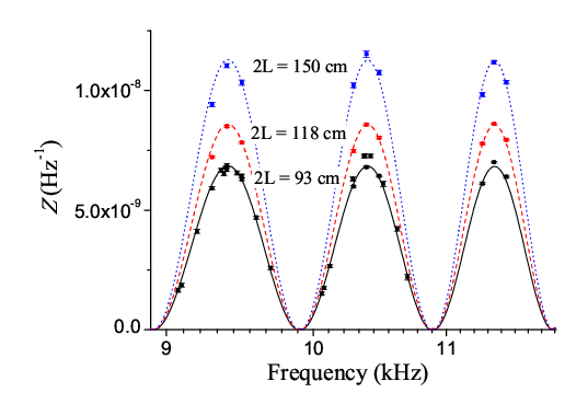
Figure 2 displays the measured and calculated transfer function as a function of the modulation frequency , for three values of the retro-reflection length: = 93, 118 and 150 cm. The weighting function zeros occur when the period of the perturbation is a multiple of . In that case, the phase of the perturbation is the same for each of the three pulses, and the corresponding interferometer phase shift vanishes. One can see on figure 2 that the experimental points agree with the calculation (eq. 7), demonstrating that the amplitude of increases linearly with the time delay .
We also test further the relation between our measurement of the transfer function and the weighting function [26]. We measure the transfer function for a fixed value of , for frequencies respectively lower and higher than the low pass cut-off frequency . In our case, a pulse is long, so is about 24 kHz. The measurements are presented in figure 3. For , there is a slight shift between the measurement and the theoretical expression of . We tested out various possible origins like the duration and timings of the pulses, the synchronization of the frequency synthesizer we used to modulate the laser frequency and the clock frequency of the experiment, but this shift is still not understood. However it does not affect the value of the variance integrated over the whole spectrum (see eq. 10).
4 Limits on the interferometer sensitivity
4.1 Theoretical analysis
We finally quantify the degradation of the interferometer sensitivity as a function of the laser frequency noise level and of the optical delay. Using the equation (5), the variance of the phase fluctuation is given by:
| (8) |
where is the power spectral density (PSD) of the master laser frequency noise. Then, using equation (6), one writes the variance as:
| (9) |
The same approximation than before () leads to the final expression:
| (10) |
According to this formula, the interferometer sensitivity increases linearly with the retro-reflection length. In the case of a white frequency noise (), the variance is:
| (11) |
This last result gives a simple evaluation of the level of white frequency noise required to reach a given sensitivity, for given retro-reflection delay and Raman pulse duration.
4.2 Example of the laser frequency noise influence
In a second experiment, the frequency noise is deliberately degraded by adding noise on the master laser current. We use a high gain amplifier with an incorporated tunable low pass filter (Stanford Research System SR650) as the noise source, with its input connected to ground. We basically control the amount of RMS frequency noise by changing the cut-off frequency of the filter (see fig. 4). The PSD of the master laser frequency noise is measured by analyzing the FVC output with a FFT analyzer (we made sure it is well above the PSD of the reference laser to which the master laser is compared). We also measure the power spectrum of the laser without additional noise, and we calculate the two corresponding variances, with or without added noise, using equation (10). The difference between the two variances gives the expected variance degradation of the interferometer phase noise. We compare this calculation with the experimental value of obtained by measuring the difference between the variances of the interferometer phase with and without added noise. The experiment was performed for cm, and the figure 5 shows the comparison between the calculated and the measured values of the variance degradation. The experimental values agree very well with the result of the calculation.
From the nominal frequency noise spectrum (curve (a) on figure 4), we estimate that the retro-reflection induces a laser frequency noise contribution of 2.4 mrad/shot to the total interferometer noise.
5 Discussion
5.1 Sensitivity limitation of the gravimeter measurement
This contribution of the frequency noise does not depend on the duration of our interferometer. Indeed, as discussed before, the retro-reflection delay can be considered as constant even for the longest interferometer we can perform. Moreover, dominant contributions to the variance arise from the high frequency part of the laser frequency noise spectrum, for which the fast oscillations of the transfer function average to the same value, regardless to .
The calculated laser frequency noise contribution induced by the retro-reflection is of the same order of magnitude than the other sources of phase noise also due to the lasers. Indeed, the PLL noise contributes for 2.1 mrad/shot [26], the various frequency references for 1.6 mrad/shot [24], and the propagation in the optical fiber for 1.0 mrad/shot. All these noise sources are independent, so the frequency noise of the Raman lasers represents a total contribution of mrad/shot to the interferometer phase sensitivity.
The phase sensitivity of 2.4 mrad/shot limits the sensitivity of the acceleration measurement up to with our experimental parameters ( ms, , cm, and cycle rate 4 Hz). However, the interferometer sensitivity is presently limited to by the vibration noise.
We want to emphasize here that our ECDL have excellent white frequency noise floor, which corresponds to a linewidth of only 5 kHz. Excess 1/f noise at low frequency is inherent to the diode lasers. It could be reduced more efficiently by using other locking techniques which allow larger bandwidths [28, 29, 30]. Other laser sources based on frequency doubled fiber lasers, whose frequency noise is extremely low, could be beneficial [31, 32]. On the contrary, DBR laser diodes, whose linewidth is typically a few MHz, are not recommended.
According to equation (11), the sensitivity may be improved by using longer Raman pulses. On the other hand, when the duration is larger, the velocity selectivity of the pulses becomes more stringent. Then the contribution of useful atoms to the signal is smaller, and the detection noise is larger. Even for the lowest temperatures one can reach with cooling, the increase of reduces either the the contrast when no primary velocity selection is performed, or the number of atoms in the measurement. Ultra-cold atoms, obtained by evaporative or sideband cooling, would be of interest [33, 34].
The sensitivity can also be improved by bringing the mirror closer to the atoms. Presently, our mirror is located at the bottom of the experiment, out of the magnetic shields. Ultimately the mirror could be installed inside the vacuum chamber, very close to the atoms. In this ideal situation, the laser propagation delay cannot be considered constant for the three pulses anymore. The maximum delay scales as the trajectory length, which is proportional to . On the other hand, the sensitivity to inertial forces also scales as when going to large interaction times. Hence, the sensitivity limit on the inertial measurement induced by the propagation delay, does not depend on for ground instruments. The situation is more favorable for space based instruments [32] where the distance between the atoms and the retro-reflection mirror would scale like the separation of the wavepackets, meaning only like .
5.2 Influence on gradiometers measurement
The formalism developed here could finally be useful to determine the ultimate performances of cold atom gradiometers. In such experiments, two atomic clouds are spatially separated and realize simultaneously gravity measurements [17, 35]. Most of the phase noise contributions are rejected thanks to the differential measurement, when the clouds experience the same Raman lasers. However, as the lasers propagation delays are not the same for the two spaced interferometers, the laser frequency noise do not cancel. Let us consider the simple case where the atomic sample is very close to the retro-reflection mirror, whereas the other is half a meter above. While the phase noise induced by the laser propagation is negligible for , for the other sample this phase noise contribution would reach the 2.4 mrad/shot that we calculated for a single sample located at cm, with our laser setup. A remarkable point is that this phase noise contribution scales like the distance , just like the sensitivity of the gradiometer measurement. Hence there would be no advantage in increasing the separation between the samples, as long as one do not increase the interaction time .
In the more common configuration where the samples are given the same initial velocity, the distance between them remains constant during their trajectories. It is then quite straightforward that the gradiometer phase noise induced by the lasers propagation delays only depend on the separation . Thus the sensitivity limit is also given by the equation 10, with . The variance in the case of a white frequency noise is then:
| (12) |
Using our experimental setup, with the parameters mentioned before, the best sensitivity would be thus (. Let us consider now an atomic fountain configuration with a vertical separation m of the two samples, and a trajectory height of 1 meter too (see figure 6). This trajectory is obtained for an initial velocity of 4 m/s, and the apogee is reached after a time interval of 450 ms, which defines the interaction time . A laser linewidth as small as 500 Hz (corresponding to a white frequency noise of about ) would allow to obtain a stability measurement of (for a standard pulse duration ).
6 Conclusion
We have investigated the influence of the optical propagation delays on the phase noise of an atom interferometer based on two photon transitions. The transfer function for the laser frequency fluctuations has been calculated and measured for various optical paths with our cold atom gravimeter. Quantitative measurements of the interferometer sensitivity have also been performed, which show that the laser frequency noise can limit the sensitivity of the interferometer. We therefore suggest that a necessary effort must be placed to reduce the laser frequency noise. Thus for experiments where vibrations are not the main limitations, for instance in the case of space applications, integrated DFB or DBR lasers are not recommended. We apply the present formalism to the case of atomic gradiometers, where the other sources of interferometer phase noise are rejected. A model is proposed to estimate the required frequency laser noise in order to reach a given sensitivity. This work presents interest for spaceborne experiments as well, where interaction times can be much longer, and where the effect of the lasers propagation could constitute a technical limitation.
The authors would like to thank the Institut Francilien pour la Recherche sur les Atomes Froids (IFRAF), the Centre National des Etudes Spatiales (contract no. 02/CNES/0282), the European Union (FINAQS) for financial support. P.C. and J.L.G. thank DGA for supporting their works.
References
- [1] G. Santarelli, Ph. Laurent, P. Lemonde, and A. Clairon, Phys. Rev. Lett. 82, (1999) 4619.
- [2] M. Kasevich and S. Chu, Phys. Rev. Lett. 67, (1991) 181.
- [3] F. Riehle, Th. Kisters, A. Witte, J. Helmcke, and Ch. J. Bordé, Phys. Rev. Lett. 67, (1991) 177180.
- [4] D.S. Weiss, B.C. Young and S. Chu, Appl. Phys. B 59, (1994) 217253.
- [5] H. Marion, F. Pereira Dos Santos, M. Abgrall, S. Zhang, Y. Sortais, S. Bize, I. Maksimovic, D. Calonico, J. Grünert, C. Mandache, P. Lemonde, G. Santarelli, Ph. Laurent, and A. Clairon, Phys. Rev. Lett. 90, (2003) 150801.
- [6] P. Wolf, F. Chapelet, S. Bize, and A. Clairon, Phys. Rev. Lett. 96, (2006) 060801.
- [7] D.W. Keith, M.L. Schattenburg, H.I. Smith, and D.E. Pritchard, Phys. Rev. Lett. 61, (1988) 1580-1583.
- [8] E.M. Rasel, M.K. Oberthaler, H. Batelaan, J. Schmiedmayer and A. Zeilinger, Phys. Rev. Lett. 75 (1995) 2633-2637, D.M. Giltner, R.W. McGowan and S.A. Lee, Phys. Rev. Lett. 75 (1995) 26382641.
- [9] Ch. Miniatura, J. Robert, S. Boiteux, J. Reinhardt and J. Baudon, Appl. Phys. B 54, (1992) 347-350.
- [10] T. Schumm, S. Hofferberth, L. M. Andersson, S. Wildermuth, S. Groth, I. Bar-Joseph, J. Schmiedmayer and P. Krüger, Nature Physics 1, (2005) 57-62.
- [11] Atom Interferometry, P.R. Berman editor, Academic Press (1997).
- [12] A. Miffre, M. Jacquey, M. Büchner, G. Trénec and J. Vigué, Eur. Phys. J. D 38, (2006) 353-365.
- [13] H. Müller, S.-W. Chiow, Q. Long, C. Vo and S. Chu, Appl. Phys. B 84, (2006) 633-642.
- [14] K. Moler, D.S. Weiss, M. Kasevich, S. Chu, Phys. Rev. A 45, (1992) 342-348.
- [15] A. Peters, K.Y. Chung and S. Chu, Nature 400, (1999) 849.
- [16] T. L. Gustavson, P. Bouyer, and M. A. Kasevich, Phys. Rev. Lett. 78, (1997) 2046-2049.
- [17] M.J. Snadden, J.M. McGuirk, P. Bouyer, K.G. Haritos, and M.A. Kasevich, Phys. Rev. Lett. 81, (1998) 971-974.
- [18] B. Canuel, F. Leduc, D. Holleville, A. Gauguet, J. Fils, A. Virdis, A. Clairon, N. Dimarcq, Ch. J. Bordé, A. Landragin, P. Bouyer, Phys. Rev. Lett. 97, (2006) 010402.
- [19] T.M. Niebauer, G.S. Sasagawa, J.E. Faller, R. Hilt and F. Klopping, Metrologia 32, (1995) 159-180.
- [20] K.U. Schreiber, A. Velikoseltsev, M. Rothacher, T. Klugel, G.E. Stedman, D.L. Wiltshire, J.Geophys.Res. 109 (2004) B06405.
- [21] C. J. Bordé, in Laser Spectroscopy X (Edited by M. Ducloy, E. Giacobino and G. Camy), Singapore, World Scientific, (1991) 239-245.
- [22] G. Santarelli, A. Clairon, S.N. Lea and G. Tino, Opt. Comm. 104, (1994) 339-344.
- [23] P. Bouyer, T. L. Gustavson, K. G. Haritos, and M. A. Kasevich, Opt. Lett. 21, (1996) 1502.
- [24] P. Cheinet, F. Pereira Dos Santos, T. Petelski, J. Le Gouët, J. Kim, K.T. Therkildsen, A. Clairon and A. Landragin, Appl. Phys. B 84, (2006) 643-646.
- [25] C. J. Bordé, Metrologia, 39, (2002) 435-463.
- [26] P. Cheinet, B. Canuel, F. Pereira Dos Santos, A. Gauguet, F. Leduc, A. Landragin, submitted to IEEE Trans. on Instrum. Meas., Arxiv physics/0510197 (2005).
- [27] G.J. Dick, Local Oscillator induced instabilities, in Proc. Nineteenth Annual Precise Time and Time Interval, (1987) 133-147.
- [28] R.W.P. Drever, J.L. Hall, F.V. Kowalski, J. Hough, G.M. Ford, A.J. Munley, H. Ward, Appl. Phys. B 31, (1983) 97.
- [29] B. Dahmani, L. Hollberg, and R. Drullinger, Opt. Lett. 12, (1987) 876-878.
- [30] V. Crozatier, F. de Seze, L. Haals, F. Bretenaker, I. Lorgeré, J.-L. Le Gouët, Opt. Comm. 241, (2004) 203213.
- [31] R. Thompson, M. Tu, D. Aveline, N. Lundblad, L. Maleki, Opt. Exp. 11, (2003) 1709-1713.
- [32] R.A. Nyman, G. Varoquaux, F. Lienhart, D. Chambon, S. Boussen, J.-F. Clément, T. Müller, G. Santarelli, F. Pereira Dos Santos, A. Clairon, A. Bresson, A. Landragin and P. Bouyer, Appl. Phys. B 84, (2006) 673-681.
- [33] N. Masuhara, J. M. Doyle, J. C. Sandberg, D. Kleppner, T. J. Greytak, H. F. Hess, and G. P. Kochanski, Phys. Rev. Lett. 61, (1988) 935-938.
- [34] H. Perrin, A. Kuhn, I. Bouchoule, T. Pfau and C. Salomon, Europhys. Lett, 46, (1999) 141-147.
- [35] N. Yu, J.M. Kohel, J.R. Kellogg and L. Maleki, Appl. Phys. B 84, (2006) 647-652.