Studies of the performance of different front-end systems for flat-panel multi-anode PMTs with CsI(Tl) scintillator arrays
Abstract
We have studied the performance of two different types of front-end systems for our gamma camera based on Hamamatsu H8500 (flat-panel 64 channels multi-anode PSPMT) with a CsI(Tl) scintillator array. The array consists of 64 pixels of which corresponds to the anode pixels of H8500.
One of the system is based on commercial ASIC chips in order to readout every anode. The others are based on resistive charge divider network between anodes to reduce readout channels. In both systems, each pixel (6mm) was clearly resolved by flood field irradiation of 137Cs. We also investigated the energy resolution of these systems and showed the performance of the cascade connection of resistive network between some PMTs for large area detectors.
Keywords:
flat-panel detector, PSPMT , gamma camera, Compton telescopePACS
85.60.H, 87.62, 87.59, 95.55.K, , , , , , , , , , ,
1 Introduction
Recently, the concern with the gamma camera based on position sensitive PMTs for application especially to nuclear medicine has been growing. The latest developed flat-panel type Hamamatsu H8500 and H9500[1] are promising devices for such purpose, and several studies have been conducted focusing on their spatial resolution with both pixellated scintillator array and continuous scintillator slab aiming at PET and SPECT applications[2, 3, 4].
The merit of such multi-anode flat-panel type PMTs is the small non-active area when they are arrayed and constitute large area detectors, however, developments of readout systems for large number of channels are indispensable.
On the other hand, Compton imaging detectors for gamma ray astronomy or next generation medical imaging has been developed[5, 6, 7] with gamma cameras used for the detection of scattered gamma rays. In such cases, not only the spatial resolution but also the energy resolution is important to reconstruct the direction of incident gamma rays.
In this paper, we report the spatial resolution and energy resolution of our gamma camera based on H8500 with two different types of front-end systems. One of the system is based on commercial ASIC chips in order to readout every anode, the others are based on the resistive charge divider network between anodes to reduce the readout channels. In order to evaluate the performance, we coupled a CsI(Tl) scintillator array which fits to the anode pitches of H8500. This camera is intended for arrayed and covering our micro time projection chamber (micro-TPC)[5], which constitutes a new Compton imaging detector[8].
2 The Detector
The Hamamatsu H8500 has a very compact dimension of 52 mm 52 mm 28 mm with 12 stages of metal channel dynodes and a HV divider circuit. The active photo cathode area is 49 mm49 mm and is covered by an 88 anode array. The typical anode gain is (HVV) and the typical anode gain uniformity (the ratio of the maximum gain to the minimum gain) is about 2.5. Each anode pixel size is 5.8 mm 5.8 mm and the pitch between center of the anodes is 6.08 mm.
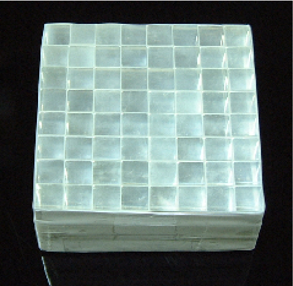
The size of each CsI(Tl) crystal is 6mm6mm20mm. The crystals were also manufactured by Hamamatsu. Between the crystals, Vikuiti ESR films (3M) of 65m are inserted for the optical isolation, so that the pixel of scintillator array corresponds to the anode pixel. The array is glued to H8500 using OKEN6262A optical grease. Fig.1 shows the picture of the array.
3 Readout circuits
3.1 CP80068 system
Fig.2 shows the individual anode readout system (Clear Pulse Co., Ltd. CP80068). The dimension of CP80068 which is designed for 2 dimensional array of H8500 is 52 mm 52 mm 95 mm. It is based on two types of analog ASICs, VA32HDR14 and TA32CG2 manufactured by IDEAS ASA. VA32HDR14 contains pre-amplifiers (input dynamic rangepC), shapers (gainmV/pC, peaking times), sample and hold circuits and a multiplexer. TA32CG32 contains fast shapers (peaking timens) and comparators, which can make the trigger signals. The multiplexed 64ch data are digitized by a flash ADC on the CP80068 and sent to the VME sequence module via FPGAs. It takes 164s to process one event (64 channels).
3.2 Resistive charge division
Fig.3 shows the charge divider network board for H8500. Using this connector board, the anodes in horizontal rows of H8500 are connected with 100 chips and the number of readout channels are reduced to 16. Each reduced channel is preamplified (integrating time constants), shaped (Clear Pulse CP4026, shaping times) and digitized (CAEN V785). The last dynode output is used as the trigger signal.
For further reduction of the readout channels, we connected the intervals of the the both edges of the horizontal chains with 100 resisters, thus 4 channels readout with resistive chain is also tested.
4 Measurements and Results
We are interested in the energy of sub-MeV region[5], accordingly, the CsI(Tl) array was irradiated by 1 MBq 137Cs source (662keV)at a distance of 30 cm. For the energy calibration, 22Na (511keV), 133Ba (356keV) and 57Co (122keV) were also used. An important point to mention here is the dynamic ranges of the readout circuits. As the input dynamic range of CP80068 is as small as pC, H8500 should be operated with the gain of (HVV) to observe 662keV gamma rays. In the case of resistive charge division circuits, dynamic ranges of the shaper and the ADC also limit the operation gain of H8500 to (HVV).
4.1 Spatial Resolution
The obtained flood irradiation images of 137Cs are shown in Fig.4. The methods of the calculation of the position reconstruction are indicated as well. Image spots represent pixels of the CsI(Tl) array, which indicates that the intrinsic spatial resolution of H8500 is better than the anode pixel size.
The accidental hit events of multi pixels were rejected in the results of CP80068 system (selection efficiency was ) and the accidental hit events of more than two horizontal rows were also rejected in the results of the 16 channels readout system (selection efficiency was ). On the other hand, in the 4 channels readout system, there is no way to reject such events, therefore the peak to valley ratios of the x/y cross section of the flood irradiation image are the worst.
4.2 Energy Resolution
| System | Best | Typical | Worst |
|---|---|---|---|
| CP80068 | 8.9% | 9.5% | 10.0% |
| 16ch readout | 8.0% | 8.7% | 9.5% |
| 4ch readout | 8.6% | 8.8% | 9.9% |
The obtained energy spectra of the best pixel of each readout system are also shown in Fig.4. The variations of the energy resolution of 662keV of every readout system are summarized in Table.1.
The variation of the resolution is mainly due to the variation of the anode gain. Near the boundary of the detection area, optical leakage (photon collection inefficiency) also affects not only the energy resolution but also the spatial resolution. Fig.5 shows the energy resolutions of measured energy of all the readout systems. The reason why the energy resolution of the result of CP80068 system is the worst is its low HV operation.
5 Discussion and Conclusion
It is admitted that individual anode readout is the best way for multi anode PMTs, however, that needs development of exclusive ASICs with consideration for the light outputs of scintillator, gain of the PMT, and the dynamic range. Moreover, in our case, the spatial resolution is not determined by the anode pixel size but by the crystal pixel size.
Therefore, the advantage of energy resolution of the resistive charge divider network and discrete modules of readout circuit is encouraging to make larger area detector. We made cascade resistive connection of 4 H8500s as shown in Fig.6 for example. The energy resolution is also shown in Fig.5 This connection is another example of 4 channels/PMT readout and crystal pixel identification is better than that of previous 4 channels readout system.
In conclusion, large area detector of pixel scintillator and H8500 array with resistive charge division systems have a good performance both energy and spatial resolutions and have many possibilities in medical and gamma ray astronomy applications.
Acknowledgement
We would like to thank Takahashi Lab. at Institute of Space and Astronautical Science, Japan Aerospace Exploration Agency, Makishima Lab. at Department of Physics, School of Scienece, University of Tokyo and Dr. Gunji for the development of CP80068.
References
- [1] Hamamatsu technical data sheet H8500-H8500B, H9500, Feb 2005, printed in Japan. http://www.hamamatsu.com
- [2] R. Pani et al., Nucl. Instr. and Meth. A 527 (2004) 54; R. Pani et al., Nucl. Instr. and Meth. A 513 (2003) 36.
- [3] M. Gimnez et al., Nucl. Instr. and Meth A 525 (2004) 298.
- [4] D. Herbert et al., Nucl. Inst. and Meth. A 518 (2004) 399.
- [5] A. Takada et al., Nucl. Inst. and Meth. A 546 (2005) 258.
- [6] G. Kanbach et al., Nucl. Inst. and Meth. A 541 (2005) 310.
- [7] A. Studen et al., Nucl. Instr. and Meth. A 531 (2004) 258.
- [8] T. Tanimori et al., New Astron. Rev. 48 (2004) 263.
- [9] ROOT, An Object-Oriented Analysis Framework, http://root.cern.ch