On Artificial Magneto-Dielectric Loading for Improving the Impedance Bandwidth Properties of Microstrip Antennas
P.O. Box 3000, FI-02015 TKK, Finland
Address for correspondence:
Pekka Ikonen,
Radio Laboratory, Helsinki University of
Technology,
P.O. Box 3000, FI-02015 TKK, Finland.
Fax: +358-9-451-2152
E-mail: pikonen@cc.hut.fi
Abstract
In the present paper we discuss the effect of artificial magneto-dielectric substrates on the impedance bandwidth properties of microstrip antennas. The results found in the literature for antenna miniaturization using magnetic or magneto-dielectric substrates are revised, and discussion is addressed to the practically realizable artificial magnetic media operating in the microwave regime. Using a transmission-line model we, first, reproduce the known results for antenna miniaturization with non-dispersive material fillings. Next, a realistic dispersive behavior of a practically realizable artificial substrate is embedded into the model, and we show that frequency dispersion of the substrate plays a very important role in the impedance bandwidth characteristics of the loaded antenna. The impedance bandwidths of reduced size patch antennas loaded with dispersive magneto-dielectric substrates and high-permittivity substrates are compared. It is shown that unlike substrates with dispersion-free permeability, practically realizable artificial substrates with dispersive magnetic permeability are not advantageous in antenna miniaturization. This conclusion is experimentally validated.
Key words: Patch antenna, high-permeability materials, magneto-dielectric substrate, frequency dispersion, quality factor, miniaturization.
1 Introduction
For a long time microstrip antennas have been miniaturized using different material fillings between the radiating element and the ground plane [1, 2, 3]. Most traditionally, high permittivity dielectrics have been used to decrease the physical dimensions of the radiator [4, 5]. Common problems encountered with high permittivity substrates include e.g. the excitation of surface waves leading to lowered radiation efficiency and pattern degradation, and difficulties in impedance matching of the antenna. During the first heyday of so called metamaterials, artificial high-permeability materials working in the microwave regime have gained increasing attention [6]–[13]. The possibility to create artificial magnetism at microwave frequencies has heated the discussion on the possibility to enhance the impedance bandwidth properties of planar radiators using magneto-dielectric substrates [17]–[21] or other electromagnetically exotic substrates [22, 23, 24].
According to the work of Hansen and Burke [25], inductive (magnetic) loading leads to an efficient size miniaturization of a microstrip antenna. A transmission-line (TL) model for a normal half-wavelength patch antenna predicts that increase in the permeability of the antenna substrate does not reduce the impedance bandwidth of the miniaturized radiator (when the material parameters are dispersion-free, and ) [25]. Edvardsson [26] derived a condition for the radiation quality factor of a planar inverted F-antenna (PIFA), and concluded that increase in the permeability allows size miniaturization without increasing . However, to draw a general conclusion on the practical applicability of the magnetic loading e.g. with mobile phone antennas, there are three things which need to be clarified: i) The effect of frequency dispersion of the substrate. Practically realizable artificial magnetic medium operating at microwave frequencies is composed of electrically small resonating metal unit cells11 1 Paramagnetic response at microwave frequencies can also be achieved using hexaferrites, or composite materials containing ferromagnetic inclusions. In the present paper we consider, however, only artificial magnetic media composed of resonating metal inclusions., thus, the magneto-dielectric substrate obeys strong frequency dispersion. Even though the substrate can be considered as a paramagnetic medium when using plane wave excitation (at the macroscopic level, over a certain frequency range), the performance is not so obvious to predict when the resonant substrate is coupled to the antenna element. ii) The effect of high compared to over the matching band of the antenna. With practically realizable artificial magneto-dielectric substrates for microwave frequencies Re is known to be rather moderate, thus in practice it seems very difficult to achieve the condition (outside the resonant region of the substrate). iii) The effect of losses. Realistic model representing the losses of the substrate is needed to correctly predict the behavior of the susceptance seen at the antenna terminal (further, the quality factor). Moreover, the numerical and experimental results found in the literature [17]–[21] do not offer a complete, quantitative comparison scheme applicable for practical antenna design. According to the authors knowledge, the impedance bandwidths (quality factors) of reduced size antennas loaded with practically realizable, artificial, dispersive magneto-dielectrics have not been compared to the results obtained using high-permittivity dielectrics leading to the same size reduction. When thinking of practical antenna design, this quantitative comparison is clearly needed to make decisions whether or not the possibly enhanced impedance bandwidth outweights e.g. the increased manufacturing cost and substrate weight.
In real life large permeabilities for microwave materials are achieved with a complex mixture of electrically small inhomogeneities (resonating unit cells) loaded into a substrate in a specific periodic arrangement. In the present paper we shortly discuss the possibilities to enhance artificial magnetism at microwave frequencies, and construct a TL model taking into account realistic dispersive behavior of a practically realizable artificial magneto-dielectric substrate. We start the analysis by reproducing the known miniaturization results with static material parameters, and further extend the study to take into account frequency dispersion. It is shown that a substrate obeying the Lorentzian type dispersion for magnetic permeability leads to a narrower impedance bandwidth than a high-permittivity substrate offering the same size reduction. Physical reason for the phenomena is clarified. A prototype antenna is constructed and the observation is experimentally validated.
The rest of the paper is organized in the following way: In section II we briefly revise the numerical and experimental results found in the literature for magneto-dielectric loading of microstrip antennas. Section III presents a short discussion on practically realizable artificial magnetic media and the used TL-model is presented in detail in Section IV. Section V presents the calculated impedance bandwidth properties in different loading scenarios, and an experimental demonstration is presented in section VI. The work is concluded in Section VII.
2 Revision of numerical and experimental results
Mosallaei and Sarabandi applied in [14] a finite-difference time-domain (FDTD) simulation scheme and investigated antenna miniaturization using a band-gap substrate consisting of dielectric and magneto-dielectric (Z-type hexaferrite) layers. Constant scalar-permeability assumption was used with substrate material parameters , at 277 MHz. Magneto-dielectric substrate was shown to lead to a significantly wider impedance bandwidth than a pure dielectric substrate offering the same size reduction. The same authors introduced in [15] an embedded circuit metamaterial structure and utilized it under a patch antenna operating at 2.3 GHz (FDTD simulations). A 1.5 percent fractional bandwidth was demonstrated for a 0.075 size patch antenna with lossless, dispersion-free substrate material parameters (). The authors did not, however, present any result for high permittivity dielectrics leading to the same size reduction. Buell et. al [16] measured the performance of a patch antenna utilizing an embedded circuit metamaterial at 250 MHz, and reported that miniaturization factors as high as 6.4 (with 0.83 percent) could be achieved. However, the radiation efficiency was measured to be only 21.6 percents, and a comparative measurement with high-permittivity dielectrics was not conducted.
Yoon and Ziolkowski [17] simulated a microstrip antenna with different material fillings (dispersion-free material parameters), and came to the conclusion that the optimal condition for the effective substrate material parameters is the same as predicted by Hansen and Burke [25], and Edvardsson [26] (). In [18] Kärkkäinen et. al numerically studied a PIFA with dispersive magnetic material filling. The authors pointed out the need to regard the loaded radiator as a system of two coupled resonators, rather than a radiator loaded with a static paramagnetic load. The conclusion was that if the resonance of the material is considerably higher than the resonance of the empty antenna, the material loading enables size reduction while approximately retaining the fractional bandwidth. The effective permittivity of the substrate was assumed to be unity, and the design utilizing dispersive magnetic filling was not challenged against a design utilizing dispersion-free dielectrics offering the same size reduction.
Ermutlu et. al [19] loaded the volume under a half-wavelength patch antenna with a practically realizable artificial magneto-dielectric material, and concluded based on numerical and experimental results that significant miniaturization factors could be achieved while the bandwidth of the loaded antenna is approximately retained. The results were not, however, challenged against results obtained using high-permittivity substrates. Authors of [20] proposed two utilization schemes for a resonant magnetic media with planar radiators. The volume under a PIFA was loaded with an array of metasolenoids [6] and the impedance bandwidth properties were experimentally investigated. When utilizing the resonant region of the metasolenoids, the authors designed a multiresonant antenna with significantly enhanced impedance bandwidth. According to the second suggestion, the metasolenoid array would behave as a paramagnetic load enabling efficient antenna miniaturization22 2 The figure of merit used to evaluate the performance of a PIFA with different material fillings is incorrectly calculated in [20]. When the figure of merit is calculated using radiation quality factor , air filling leads to the best figure of merit.. Authors of [21] loaded the volume under a half-wavelength patch antenna with an array of metasolenoids and compared the impedance bandwidth to that obtained using high-permittivity dielectrics. The result indicated that there is practically no advantage when using the metasolenoid array.
Attempts have also been conducted to miniaturize the size of planar antennas by partially filling the volume under the radiating element with backward-wave materials [28, 29]. With patch antennas, in practise, filling the volume with backward-wave material corresponds to inserting bulk inductors and capacitors to the antenna [29], thus the technique is very similar to the well known technique of size miniaturization using reactive loads. Moreover, as expected, material obeying realistic dispersive behavior results in significantly narrower impedance bandwidth than the hypothetical material with [29].
3 On practically realizable artificial magnetic media at microwave frequencies
In the present paper we restrict the discussion only to artificial magnetic media composed of resonating metal unit cells. Other ways to enhance the magnetic response include e.g. the utilization of ferrites, or composites filled with ferromagnetic inclusions [30, 31]. In general, resonant artificial magnetic media can be utilized with planar radiators in two principal ways [20]: If the resonance of the material lies inside the operational band of the (loaded) radiator, with a suitable coupling the resonance of the material can be combined with the antenna resonance, thus a multiresonant antenna is achieved. In other words, radiating particles are used instead of a real material filling. Another way is to design the material to resonate at a considerably higher frequency than the operational frequency of the loaded radiator. In the latter case it is important that the utilized material retains its effective magnetic properties over a wide frequency band, meaning that inside the operational band of the radiator the value of the real part of the effective permeability is larger than unity, Re (low losses are another desired feature). This allows one to consider the material as a paramagnetic load with (almost) constant real part for the effective permeability over the desired frequency range. A paramagnetic load will increase the inductance of the resonator, and many authors consider this as an advantage when trying to retain the impedance bandwidth characteristics in antenna miniaturization with material fillings, see e.g. [17, 25, 26].
The problem with most of the introduced designs for artificial magnetic media operating in the microwave regime [6]–[13] is the fact that the effective magnetism rapidly vanishes as the frequency deviates from the particle resonance. Usually the maximum predicted value for the real part of the effective permeability of artificial magnetic medium (with realistic bulk concentration/volume filling ratio and loss factor) is Re at the resonance [8, 9, 11, 16, 27]. This means that in practice Re of the magneto-dielectric substrate approaches unity very quickly as the frequency deviates from the material resonance. So in practice one should utilize the particles rather close to their resonance to achieve a condition Re. This further increases the effect of frequency dispersion in the impedance bandwidth characteristics. Moreover, it might not be clear anymore if the loaded antenna should be considered as a system of two coupled resonators rather than a resonator filled with a homogenous, dispersion-free material. In addition to this, usually the real part of the effective permittivity of magneto-dielectric substrates is considerably higher than the real part of the effective permeability (when the substrate is utilized well below its resonance). Thus, at microwave frequencies the condition considered e.g. by Hansen and Burke () [25] seems unlikely to be achieved with a resonant media composed of metal unit cells. For example, with the structure presented in [13] a realistic value for the real part of the effective permeability over the operational band of a patch antenna (operating well enough below the magneto-dielectric substrate resonance) is Re [27]. However, at the same time the real part of the effective permittivity can be as high as Re, even if the host substrate has a low value for the relative permittivity [27].

To give a link between the presented effective medium model and practical design for artificial magnetic media, we need to choose a unit cell for the media. In the present work we consider the metasolenoid [6, 7] as an example unit cell for practically realizable artificial magnetic media. Fig. 1. introduces the structural geometry of the metasolenoid. Metasolenoid is chosen due to its simple structural geometry enabling rather straightforward, yet accurate theoretical analysis. Moreover, experimental results can be found in the literature for the utilization of the metasolenoid under microstrip antennas [20, 21], and the effective medium model has been experimentally validated and found to be accurate [6].
4 Transmission-line model
In this section we will derive expressions for the input impedance and unloaded quality factor of an arbitrary size strip fed patch antenna (lying on top of a large, non-resonant ground plane). The impedance level seen directly at the patch edge is usually very high causing difficulties in impedance matching of the antenna. The strip feeding allows one to conveniently tune the impedance level seen at the feeding point, thus it offers a possibility to tune the matching in different scenarios. A schematic illustration of the analyzed antenna structure and the equivalent TL-model are presented in Fig. 2. The characteristic impedance of a wide microstrip line reads [32]:
| (1) |
where is the wave impedance in free space, is the height of the substrate (assumed to be the same as the height of the patch from the ground plane), is the length of the patch, and and are the effective substrate material parameters.

In the present model we neglect the effect of the material filling to the radiation conductance and the shunt susceptance representing the open end extension of the TL. This is possible if the material filling leaves the ends of the patch free so that there is a short (about the patch height) section of the empty TL just near the radiating edges (in the present analysis the length of the empty section ). With this assumption the radiation conductance and shunt susceptance read [1, 2]:
| (2) |
| (3) |
Above is the width of the patch, and is the wavelength in free space. In eq. (3) is the open end extension of the TL (with a wide microstrip ). The propagation factor in the antenna part of the TL is of the following form
| (4) |
where is the free space wave number. For the input impedance of the antenna we can write
| (5) |
where is the impedance seen from the reference plane of the first radiating slot and is the length of the feed strip. The impedance of the (narrow) feed line is [33]
| (6) |
where is the width of the feed strip. The impedance level of the feeding probe (connected to the end of the strip) is assumed to be , and the reflection coefficient is defined as
| (7) |
To relate the unloaded quality factor to the return loss characteristics, we regard the antenna as a parallel-resonant RLC circuit in the vicinity of the fundamental resonant frequency [34]. The coupling coefficient describes the quality of the matching between the source and the resonator and is defined as
| (8) |
where is the admittance of the feed line, and is the conductance of the parallel resonator. Let us assume that the criterion for the maximum VSWR inside of the band of interest is
| (9) |
In this case the fractional bandwidth can be expressed as [34]
| (10) |
where is the unloaded quality factor of the parallel resonator. Knowing the dispersive behavior of the input return loss, can be solved from (10).
A half-wavelength patch antenna fed directly at the patch edge operates as a parallel resonant circuit when . The feed strip can be interpreted as an additional inductance placed in series with the rest of the circuit. This inductance will create a series resonance above the parallel resonance, and usually the antenna operates in between the series and the parallel resonance.
The dispersive behavior of the metasolenoid array is of the following form [6] (see Fig. 1):
| (11) |
where is the cross-section area of the metasolenoid, and is a coefficient taking into account realistic bulk concentration. The total impedance of the metasolenoid reads [6]:
| (12) |
The effective permittivity of the metasolenoid array does not equal to that of the host substrate relative permittivity (). The electric resonant behavior of the metasolenoid is very weak (compared to the magnetic resonant behavior) [6], thus a good approximation for the permittivity is a frequency independent expression
| (13) |
where is a multiplication factor depending on the bulk concentration (), and is the effective permittivity of a host substrate having relative permittivity .
5 Impedance bandwidth properties
5.1 Dispersion-free material parameters
In the first case we load the volume between the patch element and the ground plane with hypothetical, lossless substrates having static material parameters. The following loading scenarios are considered (values are for the substrate material parameters): 1) , 2) , , 3) , , 4) . The empty antenna has dimensions (see Fig. 2) mm, mm, mm, mm. With the aforementioned dimensions the empty antenna resonates at 3.0 GHz. The dimensions of the patch loaded with high-, high-, and magneto-dielectric substrates are the following: mm, mm, mm, mm (high- substrate), mm (high- substrate and magneto-dielectric substrate). Feed strip width has been left as a free parameter and is used to tune the quality of coupling in different loading scenarios. With all the loading scenarios has been tuned to [34] by varying . This allows us to neglect the square root term in (10) when comparing unloaded quality factors (note that coupling fine tuning is a common procedure in practical antenna design where the goal usually is to maximize the impedance bandwidth).

Fig. 3 shows the calculated reflection coefficient for a patch filled with different substrates. The main calculated parameters are gathered in Table 1. The unloaded quality factor obtained from eq. (10) has been calculated using –6 dB matching criterion. We can observe from Fig. 3 and Table 1 that the impedance bandwidth properties behave similarly as predicted by Hansen and Burke [25]: Dispersion-free high- materials allow size miniaturization while practically retaining the impedance bandwidth whereas when using high- materials the impedance bandwidth suffers significantly. We can also observe from Fig. 3 that increase in permittivity rather quickly increases the unloaded quality factor and narrows the impedance bandwidth (case “magneto-dielectric”).
| Loading | |||
|---|---|---|---|
| cm3 | percent | ||
| Air filling | 9.4 | 12.3 | 10.9 |
| High- | 2.0 | 10.5 | 12.8 |
| High- | 2.0 | 2.5 | 53.2 |
| Magneto-dielectric | 2.0 | 5.6 | 24.0 |
5.2 Dispersive material parameters

In most of the works found in the literature for antenna miniaturization using artificial magneto-dielectric substrates (e.g. [15, 17]) the frequency dispersion of the substrate has been neglected, and scalar constant-permeability assumption is used. In other words, it is assumed that the behavior of the loaded antenna is the same if instead of embedding the full frequency dispersion to the analysis, one picks up the values for at the operational frequency of the loaded antenna. The purpose of this subsection is to check the validity of scalar constant-permeability assumption when the substrate obeys Lorentzian type dispersion for .
We start the analysis with calculating the impedance bandwidth properties when the antenna is loaded with a substrate whose material parameters correspond to practically realizable values. The dispersive behavior of of a practically realizable magneto-dielectric substrate is shown in Fig. 4. We can see that Re at 3.0 GHz. We estimate the effective permittivity of the substrate to be [27]. For the reference substrate we tune the value of the relative permittivity so that the resonant frequency of the dielectrically loaded antenna coincides with the resonant frequency of the magneto-dielectrically loaded antenna. The corresponding value for the relative permittivity of the reference dielectric substrate is found to be . The dimensions of the loaded patches are the following: mm, mm, mm, mm (magneto-dielectric substrate), mm (reference dielectric substrate). To better see the possible effect of frequency dispersion, we will also consider a loading scenario in which the dispersive magneto-dielectric substrate is replaced with a substrate having dispersion-free material parameters (picked up from the dispersion curve at the operational frequency of the loaded antenna), .

Fig. 5 shows the calculated reflection coefficient with different material fillings. The main calculated parameters are gathered in Table 2. The obtained result indicates that practically realizable magneto-dielectric substrate offers no advantages over high-permittivity dielectrics. We notice that in this particular case the frequency dispersion of the substrate is rather weak. However, this weak dispersion added to significantly high (as compared to ) leads to poor impedance bandwidth properties. If the realistic dispersive behavior of the magneto-dielectric substrate is replaced with a scalar constant-permeability, the TL-model predicts wider impedance bandwidth with magneto-dielectrics than with pure high-permittivity dielectrics, also in the case when Re Re. This result is in line with the general opinion in the literature (based on static material parameters). However, when thinking of practical antenna design, dispersion-free assumption gives a wrong impression on the applicability of the magneto-dielectric substrate.
| Loading | |||
|---|---|---|---|
| cm3 | percent | ||
| Air filling | 9.4 | 12.3 | 10.9 |
| Magneto-dielectric | 1.5 | 1.4 | 93.7 |
| Reference dielectric | 1.5 | 1.9 | 69.7 |
| Dispersion-free | 1.5 | 2.5 | 54.2 |
Next, we consider the role of high Re/Re added to dispersive . To reveal whether or not practically realizable, dispersive magneto-dielectric substrate with a low value for Re offers any advantage over (dispersion-free) low-permittivity dielectrics, we will load the antenna with dispersive (corresponding to a practically realizable substrate) and assume that Re of the substrate is unity33 3 In principe condition Re can be realized e.g. using the wire medium [35, 36]. However, condition Re is fulfilled only at one frequency, and the realized effective permittivity is necessarily dispersive.. The results for this loading scenario are again challenged against the results obtained with pure dielectrics offering the same size reduction. The size of the loaded antenna is mm, the feed strip width in both loading scenarios is mm. The reference dielectric substrate has .
Fig. 6 shows the calculated reflection coefficient with different material fillings. The main calculated parameters are gathered in Table 3. The calculated result indicates that there is no advantage in using magneto-dielectric substrates which obey the Lorentzian type dispersion rule, even if Re, and the dispersion in is weak. Thus, a high value for Re compared to Re is not the factor which eventually deteriorates the performance of the magneto-dielectric substrate.
The above discussion holds for artificial magneto-dielectric (magnetic) substrates whose static value for Re (Lorentzian type dispersion rule). According to the Rozanov limit [37] for the thickness to bandwidth ratio of radar absorbers, the thickness of the absorber at microwave frequencies (with a given reflectivity level) is bounded by the static value of magnetic permeability of the absorber. It is interesting to apply Rozanov’s observation also in antenna miniaturization, and see if a weakly dispersive magneto-dielectric substrate with static value Re offers noticeable improvement in the impedance bandwidth properties. For example, hexaferrite, or composite materials containing ferromagnetic inclusions can be used to produce the condition Re at zero frequency. Even though the dispersive behavior of of ferrites (or composites containing ferromagnetic inclusions) is usually described by the Debye type dispersion rule, we continue to study the Lorentzian type dispersion rule for the sake of clarity. Thus, we assume that it is possible to build a composite material obeying the Lorentzian type dispersion with static Re. Otherwise the dispersive behavior of is the same as depicted in Fig. 4. Moreover, .

| Loading | |||
|---|---|---|---|
| cm3 | percent | ||
| Air filling | 9.4 | 12.3 | 10.9 |
| Magneto-dielectric | 7.8 | 4.3 | 18.5 |
| Reference dielectric | 7.8 | 6.3 | 12.6 |
The dimensions of the loaded patches are the following: mm, mm, mm, mm (for both substrates). The reference dielectric substrate has . Fig. 7 shows the calculated reflection coefficient with different material fillings. The main calculated parameters are gathered in Table 4. We can observe, that the frequency dispersion in is outweighted by the increased static value for Re. Thus it seems that weak frequency dispersion modulating a static value Re leads to similar desired performance as hypothetical, high-permeability dispersion-free substrates (of course the effect of weak frequency dispersion is seen in the slightly deteriorated impedance bandwidth as compared to dispersion-free assumption).

| Loading | |||
|---|---|---|---|
| cm3 | percent | ||
| Air filling | 9.4 | 12.3 | 10.9 |
| Magneto-dielectric | 5.0 | 8.6 | 15.5 |
| Reference dielectric | 5.0 | 6.5 | 20.5 |
5.3 Relative radiation quality factor
Let us next derive an expression explicitly explaining the negative effect of frequency dispersion. We consider a long section of a transmission line (which models a resonant patch element) filled with a certain material having material parameters , in general dispersive, but lossless. A standing wave is formed under the patch. To find the energy stored under the patch we use the known relation for the volume density of electromagnetic field energy:
| (14) |
where and are the amplitudes (real) of the electric and magnetic fields. This formula holds for low-loss materials. The amplitudes change along the patch with respect to the standing wave pattern. The total energy stored under the patch can be found by integrating over the volume under the patch. For a resonant patch this results in
| (15) |
Here is the voltage amplitude (real) at the voltage maximum of the standing wave, and is the characteristic admittance of the patch (given by eq. (1)). Practically, is the voltage at the end of the patch.
In Section 4 we mentioned that usually a patch antenna is fed by a narrower microstrip line which introduces additional series inductance so that the whole system becomes double-resonant. The second, series resonance appears at a bit higher frequency when the additional inductive impedance of the narrow microstrip is compensated by the capacitive impedance of the patch above its parallel resonance. This situation is outlined in Fig. 8.
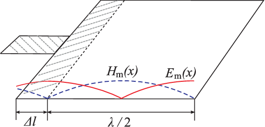
Now the total energy stored under the patch is the sum
| (16) |
where is the additional energy stored under the part of the patch that exceeds length. If we can neglect the magnetic energy stored in this segment. Then, we get
| (17) |
The amount of energy stored in the short narrow feed operating as an effective inductor can be found as follows. First, we notice that for an inductor the stored energy can be expressed in terms of the current and voltage amplitudes on the inductor:
| (18) |
At the resonance the voltage amplitudes on the reactive elements of the opposite nature are the same (if the patch susceptance dominates over the radiation conductance). Therefore, the voltage amplitude on the inductor equals the voltage amplitude at the input of the patch, and since the elements are connected in series the current through the inductor is the input current of the patch:
| (19) |
From here
| (20) |
Finally, the total energy stored in the whole system at the series resonance is
| (21) |
From above the quality factor of a resonant patch (which is the lowest possible quality factor in view of (21)) can be found as
| (22) |
Here is the radiation conductance and is the radiated power (radiation happens at the ends of the patch). For a patch antenna having the same dimensions and loaded with a reference, dispersion-free magneto-dielectric material we have
| (23) |
where is the characteristic admittance of the reference antenna. For now on we only consider resonant patches. The following holds for the ratio between the radiation quality factors:
| (24) |
Since the two antennas resonate at the same frequency we have
| (25) |
Further, if we consider the reference material to be purely dielectric () eq. (24) simplifies to
| (26) |
To be consistent with the analysis presented in the paper, we will further assume that const. In this case we obtain
| (27) |
Furthermore, we assume the dispersion of to be covered by the general (lossless) Lorentzian type dispersion rule
| (28) |
where is the amplitude factor () and is the undamped frequency of the zeroth pole pair.

The relative quality factor (eq. (27)) is presented with different amplitude coefficients in Fig. 9 (=3.3 GHz). We can observe that if the static value for Re, substrate with Lorentzian type dispersion of leads always to larger than pure dielectrics offering the same size reduction (except in the limiting case with ). This result is in line with the results presented earlier calculated using the TL-model. However, if the static Re, there exist frequency bands, over which the magneto-dielectric substrate outperforms pure dielectrics in what comes to minimized , Fig. 10. Only close to the strong frequency dispersion outweights the effect of increased static Re. Again this result agrees with the results calculated using the TL-model.


Physical understanding of the effect of frequency dispersion in the substrate material parameters can be achieved also by inspecting the input impedance of antennas loaded by dispersive magneto-dielectrics and pure dielectrics leading to the same size reduction. Fig. 11 presents the calculated input impedance when the antenna has been loaded with a practically realizable magneto-dielectric substrate and the corresponding reference substrate (the input return loss for this case is presented in Fig. 5). The known definition for the quality factor of a resonator near its parallel resonance reads:
| (29) |
Above, is the angular frequency, denotes the amount of stored energy in the volume defined by the near fields of the antenna, is the power dissipated during one cycle, is the susceptance of the resonator, and represents loss conductance. In the case of a series resonance, is replaced by the reactance , and by the loss resistance . Physically the behavior of the magneto-dielectric substrate is understandable from Fig. 11 and eq. (29): We can see that the input reactancechanges more strongly at the resonance in the case of magneto-dielectric loading. This is due to the material resonance appearing at 3.3 GHz. In terms of electromagnetic energy, this rapid change in the input reactance corresponds to increased effect of reactive near fields leading to increased amount of stored energy, thus to increased quality factor.
6 Experimental demonstration

We will manufacture a prototype antenna and load the volume under the antenna with an array of metasolenoids. For reference, the impedance bandwidth will also be measured when the volume under the antenna is loaded with high-permittivity dielectrics leading to the same size reduction. The estimated dispersive behavior of the the manufactured metasolenoid array and a photograph of the prototype antenna are shown in Fig. 12a and 12b, respectively. At the operational frequency of the loaded antenna ( = 2.07 GHz) we estimate that Re and Re (the host substrate for the metasolenoids is Rogers R/T Duroid 5870). The dimensions of the empty antenna are mm, mm, mm, mm. The dimensions of the loaded antenna are mm, mm, mm, mm. The relative permittivity for the the reference dielectric leading to the same size reduction is .
Fig. 13 and Table 5 show the measured reflection coefficient and gather the main measured parameters. The radiation efficiency has been measured using the Wheeler cap method. The unloaded quality factor obtained from eq. (10) has been calculated using –6 dB matching criterion. We can see that the impedance bandwidth behaves according to the analysis presented in the paper: Practically realizable magneto-dielectric substrate does not improve the impedance bandwidth in antenna miniaturization compared to pure dielectrics.

7 Conclusion
In the present paper we have systematically studied the effect of artificial magneto-dielectric substrates on the impedance bandwidth properties of microstrip antennas. Using the transmission-line model we have reproduced the known results for antenna miniaturization using static material parameters. Frequency dispersion of the substrate has been embedded into the analysis, and it has been shown that with artificial magneto-dielectric substrates obeying the Lorentzian type dispersion for , frequency dispersion can not be neglected in the analysis. A relation has been derived for the ratio between radiation quality factors of ideally shaped antennas loaded with dispersive magneto-dielectrics, and dispersion-free reference dielectrics. The result shows that dispersive magneto-dielectrics lead always to larger radiation quality factor (Lorentzian type dispersive behavior) if static Re. The main observation on the negative effect of frequency dispersion on the impedance bandwidth properties has been experimentally validated.
| Loading | ||||
|---|---|---|---|---|
| cm3 | percent | percent | ||
| Metasol. array | 9.2 | 3.2 | 41.5 | 89 |
| Reference dielectric | 9.2 | 5.5 | 24.3 | 92 |
Acknowledgement
Inspiring discussions with Prof. Pertti Vainikainen, Dr. Jani Ollikainen, and Dr. Murat Ermutlu are warmly acknowledged.
References
- [1] I. J. Bahl and P. Bhartia, Microstrip antennas, Massachusettes: Artech House, 1980.
- [2] C. A. Balanis, Antenna theory: Analysis and design, New York: John Wiley, 1997.
- [3] D. M. Pozar, “Microstrip antennas,” Proc. IEEE, vol. 80, pp. 79–91, 1992.
- [4] Y. Hwang, Y. P. Zhang, G. X. Zheng, T. K .C. Lo, “Planar inverted F antenna loaded with high permittivity material,” Electron Lett., vol. 31, no. 20, pp. 1710–1712, 1995.
- [5] J. S. Colburn and Y. Rahmat-Samii, “Patch antennas on externally perforated high dielectric constant substrates,” IEEE Trans. Antennas Propagat., vol. 47, no. 12, pp. 1785–1794, 1999.
- [6] S. I. Maslovski, P. Ikonen, I. A. Kolmakov, S. A. Tretyakov, M. Kaunisto, “Artificial magnetic materials based on the new magnetic particle: Metasolenoid,” Progress in Electromagnetics Research, vol. 54, pp. 61–81, 2005.
- [7] L. Jylhä, S. Maslovski, S. Tretyakov, “High-order resonant modes of a metasolenoid,” J. Electromagnetic Waves and Applications, vol. 19, no 10, pp. 1327–1342, 2005.
- [8] M. V. Kostin and V. V. Shevchenko, “Artificial magnetics based on double circular elements,” Proc. Bianisotropics’94, Périgueux, France, pp. 49–56, May 18–20, 1994.
- [9] J. B. Pendry, A. J. Holden, D. J. Robbins, W. J. Stewart, “Magnetism from conductors and enhanced nonlinear phenomena,” IEEE Trans. Microwave Theory Tech., vol. 47, no. 11, pp. 2075–2084, 1999.
- [10] R. Marqués, F. Medina, R. Rafii-El-Idrissi, “Role of bianisotropy in negative permeability and left-handed metamaterials,” Phys. Rev. B, vol. 65, 1444401(–6), 2002.
- [11] A. N. Lagarkov, V. N. Semenenko, V. N. Kisel, V.A. Chistyaev, “Development and simulation of microwave artificial magnetic composites utilizing nonmagnetic inclusions,” J. Magnetism and Magnetic Materials, vol. 258–259, pp. 161–166, 2003.
- [12] J. D. Baena, R. Marqués, F. Medina, J. Martel, “Artificial magnetic metamaterial design by using spiral resonators,” Phys. Rev. B, 69, 014402, 2004.
- [13] C. R. Simovski, A. A. Sochava, S. A. Tretyakov, “New compact and wide-band high impedance surface,” IEEE Antennas Propagat. Soc. Int. Symposium, Monterey, California, vol. 1, pp. 297–300, June 20–25, 2004.
- [14] H. Mossallaei and K. Sarabandi “Magneto-dielectrics in electromagnetics: Concept and applications,” IEEE Trans. Antennas Propagat., vol. 52, no. 6, pp. 1558–1567, 2004.
- [15] H. Mosallaei and K. Sarabandi, “Engineered meta-substrates for antenna miniaturization,” Proc. 2004 URSI Int. Symposium on Electromagn. Theory, Pisa, Italy, pp. 191–193, May 23–27, 2004.
- [16] K. Buell, H. Mosallaei, K. Sarabandi, “Embedded-circuit magnetic metamaterial substrate performance for patch antennas,” IEEE Antennas Propagat. Soc. Int. Symposium, Monterey, California, pp. 1415–1418, June 20–25, 2004.
- [17] S. Yoon and R. W. Ziolkowski, “Bandwidth of a microstrip patch antenna on a magneto-dielectric substrate,” IEEE Antennas Propagat. Soc. Int. Symposium, Columbus, Ohio, pp. 297–300, June 22-27, 2003.
- [18] M. K. Kärkkäinen, S. A. Tretyakov, P. Ikonen, “PIFA with dispersive material fillings,” Microwave Opt. Technol. Lett., vol. 45, no. 1, pp. 5–8, 2005.
- [19]
M. E. Ermutlu, C. R. Simovski, M. K. Kärkkäinen, P. Ikonen, S.
A. Tretyakov, A. A. Sochava, “Miniaturization of patch antennas
with new artificial magnetic layers,” 2005 IEEE Int. Workshop
on Antenna Technology, Singapore, pp. 87–90, March 7–9, 2005;
Also: M. E. Ermutlu, C. R. Simovski, M. K. Kärkkäinen, P. Ikonen, A. A. Sochava, S. A. Tretyakov, “Patch antennas with new artificial magnetic layers,” submitted to IEEE Wireless Component Lett. Preprint available at http://arxiv.org/abs/physics/0504075. - [20] P. Ikonen, S. Maslovski, S. Tretyakov, “PIFA loaded with artificial magnetic material: Practical example for two utilization strategies,” Microwave Opt. Technol. Lett., vol. 46, no. 3, pp. 205–210, 2005.
- [21] M. Kärkkäinen and P. Ikonen, “Patch antenna with stacked split-ring resonators as artificial magneto-dielectric substrate,” Microwave Opt. Technol. Lett., vol. 46, no. 6, pp. 554–556, 2005.
- [22] D. Sievenpiper, L. Zhang, R. F. Jimenez Broas, N. G. Alexòpolous, E. Yablonovitch, “High-impedance electromagnetic surfaces with a forbidden frequency band,” IEEE Trans. Microwave Theory Tech., vol. 47, no. 11, pp. 2059–2074, 1999.
- [23] H. Mosallaei and K. Sarabandi, “Antenna miniaturization and bandwidth enhancement using a reactive impedance substrate,” IEEE Trans. Antennas Propagat., vol. 52, no. 9, pp. 2403–2414, 2004.
- [24] Y. Zhao, Y. Hao, C. G. Parini, “Radiation properties of PIFA on electromagnetic bandgap substrates,” Microwave Opt. Technol. Lett., vol. 44, no. 1, pp. 21–24, 2005.
- [25] R. C. Hansen and M. Burke, “Antenna with magneto-dielectrics,” Microwave Opt. Technol. Lett., vol. 26, no. 2., pp. 75–78, 2000.
- [26] O. Edvardsson, “On the influence of capacitive and inductive loading on different types of small patch/PIFA structures for use on mobile phones,” ICAP Int. Conf. Antennas Propagat., Manchester, UK, pp. 762–765 April 17–20, 2001.
- [27] C. R. Simovski, Private communication, Helsinki University of Technology, April 2005.
- [28] S. F. Mahmoud, “A new miniaturized annular ring patch resonator partially loaded by a metamaterial ring with negative permeability and permittivity,” IEEE Antennas Wireless Propagat. Lett., vol. 3, pp. 19–22, 2004.
- [29] S. Tretyakov and M. Ermutlu, “Modeling of patch antennas partially loaded with dispersive backward-wave materials,” accepted in IEEE Antennas Wireless Propagat. Lett.
- [30] A. N. Lagarkov, A. V. Osipov, K. N. Rozanov, S. N. Starostenko, “Microwave composites filled with thin ferromagnetic films. Part I. Theory,” Proc. Symposium R Electromagnetic Materials, Singapore, pp. 74–77, July 3–8, 2005.
- [31] I. T. Iakubov, A. N. Lagarkov, S. A. Maklakov, A. V. Osipov, K. N. Rozanov, I. A. Ryzhikov, “Microwave composites filled with thin ferromagnetic films. Part II. Experiment,” Proc. Symposium R Electromagnetic Materials, Singapore, pp. 78–81, July 3–8, 2005.
- [32] H. A. Wheeler, “Transmission-line properties of parallel strips separated by a dielectric sheet,” IEEE Trans. Microwave Theory Tech., vol. MTT–13, pp. 2075–2084, 1965.
- [33] H. A. Wheeler, “Transmission line properties of a strip on a dielectric sheet on a plane,” IEEE Trans. Microwave Theory Techn., vol. 25, no. 8, pp. 631–647, 1977.
- [34] H. F. Pues and A. R. Van de Capelle, “An impedance-matching technique for increasing the bandwidth of microstrip antennas,” IEEE Trans. Antennas Propagat., vol. 37, no. 11, pp. 1345–1354, 1989.
- [35] S. I. Maslovski, S. A. Tretyakov, P.A. Belov, “Wire media with negative effective permittivity: A quasi-static model,” Microwave Opt. Technol. Lett., vol. 35, no. 1, pp. 47–51, 2002.
- [36] P. A. Belov, C. R. Simovski, S. A. Tretyakov, “Two-dimensional electromagnetic crystals formed by reactively loaded wires,” Phys. Rev. E, vol. 66, 036610, 2002.
- [37] K. N. Rozanov, “Ultimate thickness to bandwidth ratio of radar absorbers,” IEEE Trans. Antennas Propagat., vol. 48, no. 8, pp. 1230–1234, 2000.