2005 International Linear Collider Workshop - Stanford,
U.S.A.
LCDG4 and DigiSim – Simulation activities at NICADD/NIU
Abstract
We present two software packages developed to support detector R&D studies for the International Linear Collider. LCDG4 is a full-detector simulator that provides energy deposits from particles traversing the sensitive volumes of the detector. It has been extensively used within the American ILC community, providing data for algorithm development and detector optimization studies. DigiSim models real-life digitization effects, converting the idealized response into simulated detector readout. It has many useful features to improve the realism in modeling detector response. The main characteristics of these two complementary packages are discussed.
I INTRODUCTION
Different detector technologies are currently under investigation to be used for hadron calorimetry at the ILC (International Linear Collider). Each detector technology, with its own strengths and weaknesses, may excel at different detector geometry setups. The challenging performance goal is the ability to perform at a 30%/ jet energy resolution, which is a basic requirement for resolving from jets without ambiguity. The Particle Flow Algorithm (or PFA) is the most promising way to reach that goal. Preliminary studies indicate that only joint optimizations of detector technologies, geometries and reconstruction algorithms can satisfy this jet energy resolution goal.
The Northern Illinois Center for Accelerator and Detector Development (NICADD) at the Northern Illinois University (NIU) has been developing, in collaboration with other software development groups, basic software tools for the combined optimization of detector technologies, geometries and reconstruction algorithms. In this paper we describe software packages which have been developed as tools for detector optimization. The NIU work on PFA algorithms is described elsewheredhiman-ref.
II DETECTOR SIMULATION
In order to be useful for the detector optimization needs, a full detector simulation package must be based on a simple and flexible geometry description. It should allow all candidate technologies and geometries to be tested, and provide the data for the development of reconstruction algorithms. An important point is that not only simulation experts, but any interested user should be able to make geometry changes to an existing detector description and analyze the effects of those changes.
II.1 The LCDG4 package
LCDG4lcdg4-ref is a general purpose, Geant4geant4-ref-based full-detector simulation package. The detector geometry is described using a powerful and easy to change XML-based schema (called lcdparm). It is compatible with the I/O data formats used in US, namely STDHEPstdhep-ref for input, and LCIO or SIO for output. LCIOlcio-ref has been adopted as the standard data format to be used within the worldwide ILC community, while SIOsio-ref has been, and still is, extensively used within the US ILC community.
The main limitation of LCDG4 is the limited number of geometrical volumes available in the lcdparm schema used, allowing only disks, cylinders and cones. This limitation is not a problem when studying global geometry parameters, but it is clear that the lcdparm schema has to be extended to describe more realistic detectors.
II.1.1 Geometry representation
An example of the lcdparm XML schema for geometry representation is illustrated in Fig. 1, which shows the lcdparm description of a 55-layers hadronic calorimeter barrel. Each layer contains a 0.5 cm scintillator polystyrene layer preceded by 0.7 cm of tungsten absorber. The inner radius and the half-length of the barrel cylinder are also shown. The sensitive layers can be virtually segmented, either projectively (segmentation tag, for cells subtending constant solid angle from the center of the detector) or non-projectively (cell_grid tag, for cells of constant linear dimensions).
?xml version=”1.0” ? !DOCTYPE lcdparm SYSTEM ”detParms.dtd” … lcdparm global file=”SDNPCalMar05-scint.xml” / physical_detector topology=”silicon” id = ”SDNPCalMar05-scint” … volume id=”HAD_BARREL” rad_len_cm=”1.133” inter_len_cm=”0.1193” tube barrel_dimensions inner_r = ”138.26” outer_z = ”261.85” / layering n=”55” slice material = ”W” width = ”0.7” / slice material = ”Polystyrene” width = ”0.5” sensitive = ”yes” / slice material = ”Air” width = ”0.3” / /layering cell_grid longit=”1.0” transv=”1.0” outer_r=”220.76”/ !–segmentation theta = ”1024” phi = ”1024” /– /tube calorimeter type = ”had” / /volume … /physical_detector … /lcdparm
Fig. 2 shows the event display of a typical event processed through LCDG4. Many trajectories can be easily followed in the highly segmented calorimeters before showering starts. Hits from individual particles in jets can be separated using the full 3D information from the hits in the jet shower, depending on the calorimeter granularity and two-particle separation.


II.1.2 Certification
The calorimeter simulation in LCDG4 was certified by comparing its output with that of another detector simulator package, Mokkamokka-ref, which is mainly used in Europe. We used the then-current Mokka version 1.5. Equivalent detector geometries were implemented in both packages, and all relevant simulation parameters were checked to be identical. Material densities, radiation lengths, etc. were equivalent to better than 0.1%. The distributions compared include energy depositions per cell and per layer, hit multiplicity, and longitudinal profile of energy distribution. A typical result of such comparison is shown in Fig. 3. There is a very good agreement between the two independent packages.


II.1.3 Perspectives
Several single-particle and physics samples have been processed through LCDG4, and are freely availablesamples-ref, in both SIO and LCIO data formats. These samples have been used in several analyses and algorithm development studies presented at this workshop.
As mentioned before, the main limitation of LCDG4 was the small number of supported geometrical volumes in lcdparm schema. However, some other user requirements have been suggested for the new generation of detector simulation software. Instead of adding new features to LCDG4, a more appropriate path would be to develop a new Geant4 application from the ground up, using the best features of LCDG4, Mokka and other simulators.
The new package, called SLICslic-ref, is currently under development, and is discussed elsewhere in this proceedings. This means that LCDG4 will not have any further significant developments. Instead, it will be basically maintained, and used for data production until SLIC becomes ready for production.
III DIGITIZATION SIMULATION
Beyond the ideal detector simulation software described in the previous section, the appropriate comparisons of different detector technologies must also include real life digitization effects present in the data collection process. Typical examples include signal integration, amplification, attenuation, saturation, discrimination, crosstalk and noise characteristics and some other effects that may differ significantly between different detector technologies.
It is also important to have a common software framework for the digitization simulation, which is general enough to allow for the parametrization of the dominant characteristics of different technologies, yet simple enough for hardware developers to introduce their own parametrizations at will.
It is desirable that this package can be used either as a stand-alone processor after the detector simulation, or as an on-the-fly preprocessor to reconstruction/analysis tasks. As a stand-alone processor, DigiSim produces persistent output files, with identical structure as the real data to be eventually collected, except that the simulation output also contains the Monte Carlo truth information. On the other hand, when used as an on-the-fly preprocessor, DigiSim needs to be available within the same framework used for the reconstruction or analysis task. Note that different frameworks are commonly used in Europe (C++ based Marlin) and US (Java based org.lcsim), so both of these languages are supported.
III.1 The DigiSim package
The purpose of the DigiSim packagedigisim-ref is to do detector digitization, for the CALICEcalice-ref beam tests as a first goal, and ultimately for the full ILC detector(s). It is readily available for download and use, both as a standalone Marlin module (in C++), and as one of the packages within the org.lcsim framework (in Java).
The package reads the LCIO files produced by Geant4 applications (like LCDG4, Mokka or SLIC) and appends the raw hits produced to the output events. Most of the DigiSim (re)configuration can be done at run time by editing an ASCII steering file, no recompilation is necessary. Conveniently, the same ASCII file can be used for both the C++ and the Java versions.
DigiSim has been designed to simulate the digitization process in successive steps, performed by independent modules called modifiers. The existing modifiers (digitization classes) are easy to setup and configure, and new functionality can be added easily by creating new modifiers. LCIO format is used for both input and output files. DigiSim is thus a powerful tool for detector technology comparisons, very simple to use and extend. It has been endorsed for use within the CALICE collaboration, and is suitable for simulation of calorimeter and tracker digitization for the ILC full-detector models.
III.1.1 How DigiSim works
The purpose of DigiSim is to simulate raw hits (integer ADC counts and time stamps) starting from simulated hits (energy, timing and Monte Carlo information in floating point variables). DigiSim does this using intermediate floating point objects (TempCalHit), that serve as both input to and output of the modifiers. Ideally, each modifier represents an individual digitization process, although some very simple processes can be combined into a single modifier. This scheme is illustrated in Fig. 4.
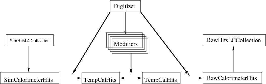
In such a scheme, the full digitization process of a given subdetector is represented by a chain of modifiers, managed by a digitizer (one digitizer per subdetector). Each modifier applies successive transformations to their input hits, handing out their output hits to the next modifier in the chain. The output from the chain of modifiers is used to create the raw hits, which are then simply appended to the LCEvent. The external framework takes care of all the I/O involved. Observe that the mapping between raw and simulated hits is not one-to-one, due to crosstalk, noise and threshold effects, but the final relationships between raw hits and the original simulated hits is also stored into the DigiSim output.
III.1.2 DigiSim implementation
The DigiSim package was implemented originally in C++, to be used within the CALICE collaborationcalice-ref, as a testbed for the full detector digitization. It was subsequently ported to Java, and all developments since then have been performed in the Java version. Consequently, the Java version has more features at this time, but we intend to support stable equivalent versions in C++ and Java in the near future.
Fig. 5 shows a DigiSim class diagram, to explain how the DigiSim implementations in Java and C++ use the same class names and interfaces, as much as these languages allow. The most significant differences between the two implementations are in the classes that interface DigiSim to their calling framework. The names of the interfacing classes make this clear: DigiSimProcessor inherit from the Marlin Processor (C++), while DigiSimDriver inherit from the org.lcsim Driver (Java). These two classes adapt the common interfaces of the core DigiSim classes to each corresponding framework, simplifying considerably the process of porting any development made in one programming language to another, thus simplifying the synchronization between different implementations.

III.1.3 Perspectives
DigiSim documentation is availabledigisim-ref, with detailed instructions on downloading, installation, usage and also on how to extend DigiSim, to enable the simulation of new digitization processes, or modify any of the existing parametrizations or algorithms.
The current implementation of DigiSim applies common parametrizations to all the sensitive elements of a given subdetector. Once the real detector is built, DigiSim is expected to support different cell-by-cell parametrizations. Such configuration parameters may come from a calibration database, for instance.
IV STUDIES AND RESULTS
IV.1 LCDG4
Several ILC-related studies have been performed using simulation data from LCDG4, particularly in the US. Some of these studies have been presented at this conferenceothers-ref. LCDG4 has thus been very useful for detector design and optimization studies, and several new results are expected to be presented in the upcoming months, including the Snowmass workshop (August 2005).
IV.2 DigiSim
Most of the detector characteristics relevant to data acquisition and digitization are still being studied by the detector hardware groups. We plan to perform studies quantifying how the digitization of a scintillator based hadronic calorimeter would affect the performance of a typical PFA by comparing its performance on data before and after DigiSim package processing. For this purpose, we will need to have dependable parametrizations for the relevant detector digitization processes. This is work in progress at NICADD/NIU.
For now, the results we can show about DigiSim just illustrate that its output makes sense. We emphasize that the current state of parametrizations are only preliminary, often mere guesses. With this fact in mind, we present below some distributions to illustrate the cumulative effect of each modifier along a given modifier chain.
As an example, we will show the effects of the following modifier chain configuration, applied to the output of LCDG4. The results shown were obtained using the Java version of DigiSim, although equivalent distributions should be obtained using the C++ version as well, once the conversion to C++ is complete.
Fig. 6 shows the DigiSim configuration file used, with the chain of modifiers and their configuration parameters. For explanations or more details about the modifier parameters used, the user is referred to the DigiSim documentationdigisim-ref.
.begin HcalBarrDigitizer ProcessorType DigiSimProcessor InputCollection HcalBarrHits OutputCollection HcalBarrRawHits Raw2SimLinksCollection HcalBarrRaw2sim ModifierNames HBlightYield HBcrosstalk HBlightCollEff SiPMQuEffic HBExpoNoise HBGaussNoise HBdiscrim HBGain # Parameters: # modifierName Type gainNom gainSig thresh thrSig HBlightYield GainDiscrimination 10000000 0 0 0 # Crosstalk mean sigma HBcrosstalk Crosstalk 0.020 0.005 # Smeared gain parameters: gain gainSigma HBlightCollEff SmearedGain 0.0111 0.0029 SiPMQuEffic SmearedGain 0.15 0 ### Noise generators # GaussNoise parameters: sys be Ecut TimeNom TSig Mean Sigma HBGaussNoise GaussianNoise 3 0 7 100 100 0.0 1.6 # ExponentialNoise parameters: sys be Ecut TimeNom TSig Mean HBExpoNoise ExponentialNoise 3 0 7 100 100 0.6 # SiPM with saturation at about 2200 incident photons # SiPMSaturation parameters: gainNom linMax HBSiPMSaturat SiPMSaturation 1 2200 # Hot cell parameters: AmplNom Sig TimeNom Sig sys be lay the phi HBHotCell HotCell 252525 0 101010 0 3 0 12 123 345 # Hot cell parameters: sys be lay the phi HBDeadCell DeadCell 3 0 12 34 56 # Discrimination threshold sigma HBdiscrim AbsValueDiscrimination 8 1 # Gain adjustments (temporary, test modifiers, etc) HBGain SmearedGain 60.06 0 .end
Some explanation for the configuration file shown in Fig. 6 is in order. The overall format of the file is mandated by the Marlin framework, though by design, the same file is also used for the Java version for convenience. Lines starting with # are comments. The first line is the name of the subdetector digitizer. After the LCIO collection names used (lines 3-5), names for the modifiers making up the modifier chain for this subdetector are listed in the order that they will be called. Each of those modifiers is then configured in the lines that follow. For instance, HBlightYield is a GainDiscrimination-type modifier that requires 4 parameters. First two parameters, say and , are the factor and its smearing, , which are drawn for each hit individually following a gaussian distribution – the so-called smeared linear transformation to hit energies. The next two parameters have a similar interpretation for a discrimination threshold: the mean value and its smearing, also drawn for each hit individually from a gaussian. Note that we could have used a SmearedGain here as well, because no threshold was applied at this level.
The modifier named Crosstalk models light crosstalk at a rate of 2% to the first neighbors, without second-order crosstalk. Some smearing has been used at the light collection modifier, namely 0.01110.0029 for a smeared value of 1.11% for collection efficiency. Exponential and gaussian noise parametrizations are available, and both are useful to model the noise of the photosensors, although the noise numbers above are just guesses. A 7 PE threshold was used for both of these noise modifiers, affecting noise-only hits, while a 8 PE cut was applied later by the HBdiscrim modifier.
Fig. 7 shows the result, in a MIP particles sample, of the consecutive application of several modifiers, according to the configuration file shown on Fig. 6. The smearing, noise and crosstalk effects are apparent in the final (digitized) distribution.

V SUMMARY AND PERSPECTIVES
In this paper we have presented the current status of the two most important NIU-developed tools currently in use, namely the full detector simulation package LCDG4 and the digitization simulation package DigiSim.
LCDG4 has been widely used within the US ILC community, specially for those groups involved in calorimeter clustering and particle flow algorithms. Several important results based on LCDG4 have been presented at this workshop. LCDG4 will become deprecated, when SLIC becomes ready for data production and algorithm developers stop using SIO data in favor of the recommended LCIO. Until then, we will continue to maintain LCDG4, and use it to provide data for algorithm development and detector optimization studies.
DigiSim, as a framework for digitization simulations, is ready for production use. Some extensions are foreseen, like independent cell-by-cell configuration from a database. It has been implemented in both Java and C++ frameworks, using a common set of classes and interfaces.
We presented the effect of a hypothetical configuration for digitization simulation, comparing digitized (real) to simulated (ideal) data, and the result of the incremental application of the chain of modifiers. The resulting plots demonstrate that DigiSim package is producing results as expected.
Acknowledgements.
The authors wish to thank the developers of org.lcsim and Marlin frameworks. This work is supported in part by grants from the US Departments of Education and Energy, and the National Science Foundation.References
- (1) Presentation by D. Chakraborty, these proceedings (PSN1016).
- (2) LCDG4 web page, http://nicadd.niu.edu/lcdg4
- (3) S. Agostinelli et. al. (Geant4 collaboration), NIM A 506 (2003), 250-303
- (4) StdHep web page, http://cepa.fnal.gov/psm/stdhep
- (5) F. Gaede, T. Behnke, N. Graf and T. Johnson, “LCIO: A persistency framework for linear collider simulation studies,” eConf C0303241, TUKT001 (2003) [arXiv:physics/0306114].
- (6) A.P.Waite, “The SIO Manual”, from http://www-sldnt.slac.stanford.edu/nld/new/Docs/FileFormats/sio.pdf
- (7) Mokka web site, http://polywww.in2p3.fr/geant4/tesla/www/mokka/mokka.html
- (8) Secure access instructions in http://nicadd.niu.edu/jeremy/admin/scp/ , subdirectory pub/lima/lcdg4
- (9) SLIC web site, http://www.lcsim.org/software/slic
- (10) DigiSim web page, http://nicadd.niu.edu/digisim
- (11) Presentations by Mader (PSN0926), von Toerne (PSN0927), Magill (PSN1015) and D. Chakraborty (PSN1016), these Proceedings
- (12) Calice web site, at http://polywww.in2p3.fr/flc/calice.html