Nuclear spin gyroscope based on an atomic co-magnetometer
Abstract
We describe a nuclear spin gyroscope based on an alkali-metal–noble-gas co-magnetometer. An optically pumped alkali-metal vapor is used to polarize the noble gas atoms and detect their gyroscopic precession. Spin precession due to magnetic fields as well as their gradients and transients can be cancelled in this arrangement. The sensitivity is enhanced by using a high-density alkali-metal vapor in a spin-exchange relaxation free (SERF) regime. With a K–3He co-magnetometer we demonstrate rotation sensitivity of . The rotation signal can be increased by a factor of 10 using 21Ne due to its smaller magnetic moment and the fundamental rotation sensitivity limit for a 21Ne gyroscope with a 10 cm3 measurement volume is about rad/sec/Hz1/2.
Sensitive gyroscopes find a wide range of applications, from inertial navigation to studies of Earth rotation and tests of general relativity Stedman1997. A variety of physical principles have been utilized for rotation sensing, including mechanical sensing, the Sagnac effect for photons Stedman1997; FiberOpRev and atoms AtomIntPRL; ColdAtomInt, the Josephson effect in superfluid 4He and 3He Avenel and nuclear spin precession Woodman87. While state-of-the-art mechanical gyroscopes, such as those developed for Gravity Probe B GravityB, remain unchallenged in terms of sensitivity, their extremely high cost and difficulty of fabrication motivate the development of simpler, smaller and more robust rotation sensors.
Here we describe a new gyroscope based on nuclear spin precession. Unlike the atom and photon interferometric gyroscopes based on the Sagnac effect, nuclear spin gyroscopes do not require a large area enclosed by the interferometer and can be made quite compact. Previous nuclear spin gyroscopes Woodman87 have suffered from high sensitivity to magnetic fields. We show that a co-magnetometer using spin-polarized noble gas and alkali-metal vapor can eliminate the sensitivity to magnetic fields, their gradients and transients. High short-term rotation sensitivity can be achieved with an alkali-metal magnetometer operating in the SERF regime Allred. For example, magnetic field sensitivity of 0.5 fT/Hz1/2 that has been demonstrated in a K magnetometer Kominis would result in a rotation sensitivity of rad/s/Hz1/2 in a K-21Ne gyroscope. The bandwidth and transient response of the gyroscope are also significantly improved compared with earlier spin gyroscopes by damping due to coupling between noble gas and alkali-metal spins. We describe an experimental implementation of the gyroscope using K and 3He atoms and demonstrate short term rotation sensitivity of with a sensing volume of only 0.5 cm3. We also present a theoretical analysis and experimental measurements of the gyroscope response to various perturbations, and derive fundamental limits for its performance.
The co-magnetometer consists of a spherical glass cell containing an alkali metal, several atmospheres of noble gas and a small quantity of nitrogen. Alkali atoms are polarized by optical pumping and transfer the polarization to the noble gas nuclei by spin-exchange collisions. A probe laser passes through the cell perpendicular to the pump laser and measures the direction of the alkali-metal polarization, which is strongly coupled to the nuclear polarization of the noble gas due to the imaginary part of the spin-exchange cross-section. For sufficiently high buffer gas pressure in a spherical cell, this coupling can be represented by an effective magnetic field that one spin species experiences from the average magnetization of the other, , where Shaefer. Here is an enhancement factor due to the attraction of the electron wavefunction towards the noble gas nucleus and ranges from about 5 to 600 for different alkali-metal–noble-gas pairs Walker.
It was shown in Kornack02 that the co-magnetometer is accurately described by a system of coupled Bloch equations for the electron and nuclear polarizations, and :
| (1) |
Here is the mechanical rotation, and are the gyromagnetic ratios of electron and nuclear spins. and are the magnetizations of electron and nuclear spins corresponding to full spin polarizations. is the effective magnetic field for alkali-metal spins created by the light shift from pumping and probing lasers HapperLS. and are the pumping rates of the pump and probe laser beams while and give the directions and magnitudes of their photon spin polarizations. is the alkali-metal–noble-gas spin-exchange rate for an alkali atom and is the same rate for a noble gas atom. is the total spin relaxation rate for alkali atoms; , where is the electron spin destruction rate. is the nuclear spin relaxation rate. is the electron slowing-down factor due to hyperfine interaction and spin-exchange collisions Savukov. For alkali metal isotopes with in the regime of fast alkali-metal spin-exchange, ranges from 6 for low to 4 for .
The co-magnetometer is nominally configured with the pump beam directed along the axis and the probe beam directed along the axis. A compensating field exactly cancels the field due to the magnetized atoms Kornack02. Here the effective field from nuclear magnetization is typically on the order of a few mG and the effective field from the electron magnetization is on the order of a few G. The light shifts can be set to zero, , because the pump beam is tuned to the center of the optical resonance and the probe beam is linearly polarized. Under these conditions the gyroscope signal, proportional to the optical rotation of the probe beam due to , is accurately given by
| (2) |
Thus, the signal is proportional to rotation about the axis and is enhanced by the ratio . The nuclear spin-exchange correction factor is typically on the order of .

Our experimental implementation of the gyroscope using K and 3He atoms is similar to the setup in Kornack02 and is depicted in Fig. 1. The floating optical table is equipped with a piezo actuator to induce small rotations and 6 non-contact position sensors to measure the resulting rotational motion. Feedback circuits were implemented to control the wavelength and intensity of pump and probe lasers. Magnetic fields and light shifts were periodically zeroed using a modulation procedure described below.

Fig. 2 shows the angular velocity signal measured by the spin gyroscope compared with the angular velocity obtained from the position sensors. The gyroscope sensitivity was calibrated as described below and agreed with mechanical measurements within the calibration accuracy of 3%. We also verified that the gyroscope is insensitive to the other two components of angular velocity.
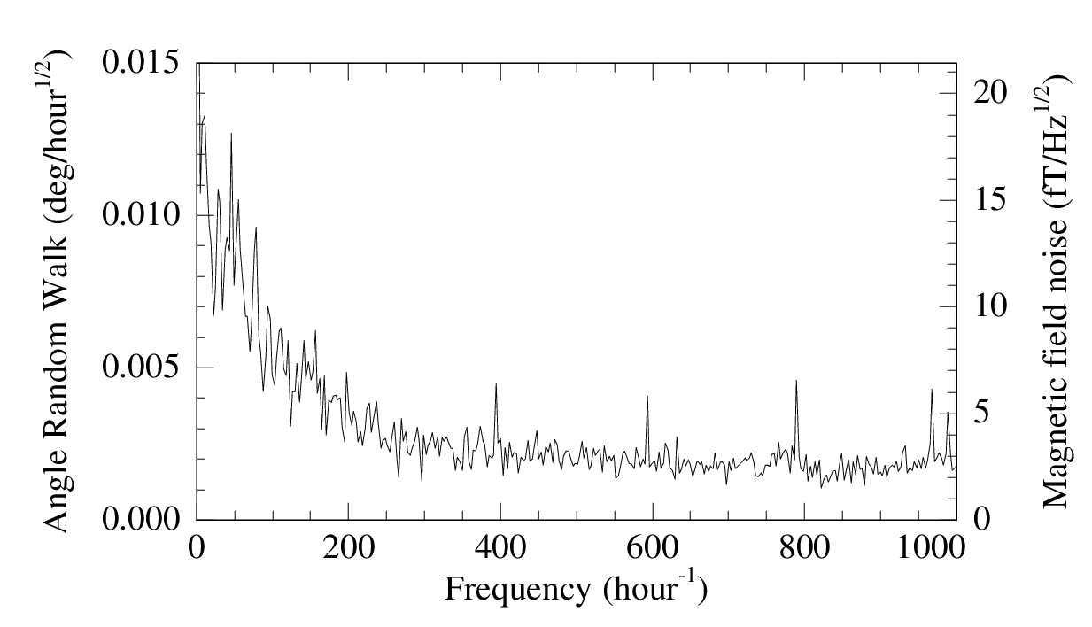
The sensitivity of the gyroscope is shown in Fig. 3. The angle random walk (ARW) is 0.002 deg/hour1/2 or rad/s/Hz1/2 in the white noise region and corresponds to a magnetic field sensitivity of 2.5 fT/Hz1/2. The low frequency angle drift of the gyroscope in the present implementation is about 0.04 deg/hour.
To understand the effects of various experimental imperfections it is important to consider small corrections to Eq. (2). The only first order dependence on the magnetic fields or light-shift fields comes from the field:
| (3) |
where the electron spin-exchange correction and is on the order of . Because electron and nuclear spin-exchange corrections are small and , the field sensitivity is suppressed by a factor of under typical conditions. Misalignment of the pump and probe beams by an angle away from 90∘ gives a signal . For typical conditions, 1 rad of misalignment gives a false rotation of rad/sec. Misalignment can be distinguished from a true rotation signal by its dependence on the pumping rate . Possible circular polarization of the probe laser also gives a first-order signal but it can be set to zero by minimizing the light shift as described below.
Other imperfections only affect the signal to second order in small quantities. For example, the signal due to the field is given by
| (4) |
where is a small detuning away from the compensation field . In addition to suppressing imperfections by two small factors, such second order dependence allows us to calibrate the co-magnetometer and provides a mechanism for zeroing many offsets. For example, to set to zero we apply a modulation to the field, measure the response as a function of and find the point where it vanishes. The slope of the response is given by
| (5) |
The approximations in the last step are accurate to better than 1% because under typical conditions and . The measurement of the slope gives a calibration of the gyroscope signal (2) in terms of the known applied magnetic fields , and . Most other field, light shift and alignment imperfections can be minimized in a similar way with an appropriate choice of modulation. For example, a term in the signal proportional to allows us to minimize the light shifts of the pump and probe beams by modulating one of them and adjusting the other to get zero response. Since , this also minimizes the probe circular polarization.
The transient response of the gyroscope is also improved in the co-magnetometer configuration. In navigation applications, the rotation frequency is integrated over time to obtain the rotation angle. Using the Green’s function for linearized Bloch equations Kornack02, it can be shown that the integral of the signal is proportional to the total angle of mechanical rotation about the axis independent of the time dependence of . Furthermore, the net rotation angle generated by an arbitrary magnetic field transient is equal to zero as long as spin polarizations are rotated by a small angle during the transient. Fig. 4 shows the response of the gyroscope to a transient magnetic field spike, demonstrating reduction of the spin rotation angle by a factor of 400 relative to an uncompensated K magnetometer. For an oscillating magnetic field the largest contribution to the signal comes from the field. For the signal is equal to
| (6) |
and is suppressed at low frequencies. The response of the co-magnetometer to oscillating magnetic fields is shown in Fig. 5 and is in close agreement with Eq. (6),


The coherent spin coupling between alkali-metal and nuclear spins also causes fast damping of transient excitations, which decay with a time constant
| (7) |
The decay time is on the order of 0.1 sec and is not limited by the nuclear spin relaxation time that is typically thousands of seconds. Fast damping of nuclear spin coherence ensures that coherent nuclear quadrupole interactions with cell walls, which produce beats in spin precession signal for isotopes with on a time scale HapperQuad; Chupp do not cause a significant effect.
The co-magnetometer also effectively suppresses magnetic field gradients even though alkali-metal and noble gas polarizations have somewhat different spatial distributions. The degree of nuclear polarization is very uniform across the cell because the rate of diffusion , where is the diffusion constant and is the radius of the cell, is much faster than . The direction of nuclear polarization is parallel to the local magnetic field as long as the nuclear spin precession frequency Cates. Thus, nuclear magnetization largely cancels the non-uniform external field point-by-point. The limits of this cancellation are determined by the degree of nuclear spin misalignment given by and the local variation in due to non-uniform alkali-metal polarization, on the order of . Both effects are on the order of under typical conditions. We measured the sensitivity to first order magnetic field gradients using internal gradient coils. The quasi-static signals from gradient fields are suppressed relative to by a factor of 500 to 5000.
The fundamental limit on gyroscope sensitivity is due to spin projection noise. We performed a quantum trajectory simulation of the coupled spin system (1) to show that for most parameters the measurement uncertainty is dominated by the alkali-metal spins. The rotational uncertainty per unit bandwidth is given by where is the density of alkali-metal atoms and is the measurement volume. 21Ne gives the best fundamental sensitivity and suppression of systematic effects because it has a small gyromagnetic ratio , ten times smaller than 3He. Using the K-21Ne spin relaxation cross-section measured in Franz we estimate the fundamental sensitivity to be rad/sec/Hz1/2 for a measurement volume of 10 cm3, K density of 1014 cm-3 and 21Ne density of cm-3. Detection of off-resonant optical rotation allows one to approach the spin projection noise even with imperfect detectors by making a quantum-non-demolition measurement of the alkali-metal spin in an optically-thick vapor.
For comparison, gyroscopes utilizing the Sagnac effect have achieved sensitivities of rad/sec/Hz1/2 using a ring laser with an enclosed area of 1 m2 Stedman2003 and rad/sec/Hz1/2 using an atomic inteferometer with a path length of 2 m AtomIntSens. More compact atomic inteferometers using cold atoms that are presently being developed have a projected shot-noise sensitivity of rad/sec/Hz1/2 ColdAtomInt and rad/sec/Hz1/2 AtomGermany. Compact state-of-the-art fiber-optic gyroscopes have a reported sensitivity of rad/sec/Hz1/2 Honeywell. Thus, the gyroscope described here is promising as a compact rotation sensor that can rival existing technologies. It’s relative simplicity makes it amenable to miniaturization with techniques developed for compact atomic clocks Kitching. Many aspects of the system, such as magnetic shielding and mechanical stability will improve with smaller size. Small size and fast transient response may also allow reduction of the gyroscope long-term drifts using active rotation techniques Subnav.
In conclusion, we have described the operation and performance of a K–3He co-magnetometer gyroscope. It has a high short term sensitivity with a small measurement volume and is insensitive to external perturbations. Further improvement is possible by switching to 21Ne gas and improving the sensitivity of optical rotation measurements at low frequencies to approach the spin-projection noise. We thank Tom Jackson, Igor Savukov, Charles Sule and Saee Paliwal for assistance in the lab. This work was supported by NASA, NSF, a NIST Precision Measurement grant, and the Packard Foundation.
References
- [1] G. E. Stedman, Rep. Prog. Phys. 60, 615 (1997).
- [2] I. A. Andronova, G. B. Malykin, Physics - Uspekhi 45, 793 (2002).
- [3] T. L. Gustavson, P. Bouyer, and M. A. Kasevich, Phys. Rev. Lett. 78, 2046 (1997).
- [4] F. Yver-Leduc et al., J. Opt. B: Quantum Semiclass. Opt. 5, S136 (2003).
- [5] O. Avenel, Yu. Mukharsky, and E. Varoquaux, Jour. Low Temp. Phys. 135, 745 (2004).
- [6] K. F. Woodman, P. W. Franks, and M. D. Richards, The Journal of Navigation 40, 366 (1987).
- [7] S. Buchman et al., Physica B 280, 497 (2000).
- [8] J. C. Allred, R. N. Lyman, T. W. Kornack, and M. V. Romalis, Phys. Rev. Lett. 89, 130801 (2002).
- [9] I. K. Kominis, T. W. Kornack, J. C. Allred and M. V. Romalis, Nature 422, 596 (2003).
- [10] S. R. Schaefer et al., Phys. Rev. A 39, 5613 (1989).
- [11] T. G. Walker, Phys. Rev. A 40, 4959 (1989).
- [12] T. W. Kornack and M. V. Romalis, Phys. Rev. Lett. 89, 253002 (2002).
- [13] W. Happer and B. S. Mathur, Phys. Rev. 163, 12 (1967).
- [14] I. M. Savukov and M. V. Romalis, Phys. Rev. A 71, 023405 (2005).
- [15] Z. Wu, W. Happer, M. Kitano, and J. Daniels, Phys. Rev. A 42, 2774 (1990).
- [16] T. E. Chupp et al., Phys. Rev. Lett. 63, 1541 (1989).
- [17] G. D. Cates, S. R. Schaefer, and W. Happer, Phys. Rev. A 37, 2877 (1988).
- [18] F.A. Franz and C. Volk, Phys. Rev. A 26, 85 (1982).
- [19] G. E. Stedman, K. U. Schreiber and H. R. Bilger, Class. Quantum Grav. 20, 2527 (2003).
- [20] T. L. Gustavson, A. Landragin and M. A. Kasevich, Class. Quantum Grav. 17, 2385 (2000).
- [21] C. Jentsch, T. Müller, E. M. Rasel, and W. Ertmer, Gen. Rel. and Grav. 36, 2197 (2004).
- [22] S. J. Sanders, L. K. Strandjord, and D. Mead, in 15th Opt. Fib. Sens. Conf. Tech. Digest, p. 5 (2002).
- [23] S. Knappe et al., App. Phys. Lett. 85, 1460 (2004).
- [24] K.M. Hays et al. 2002 IEEE Pos. Loc. and Nav. Symp. 179 (2002).