A catastrophe model for fast magnetic reconnection onset
Abstract
A catastrophe model for the onset of fast magnetic reconnection is presented that suggests why plasma systems with magnetic free energy remain apparently stable for long times and then suddenly release their energy. For a given set of plasma parameters there are generally two stable reconnection solutions: a slow (Sweet-Parker) solution and a fast (Alfvénic) Hall reconnection solution. Below a critical resistivity the slow solution disappears and fast reconnection dominates. Scaling arguments predicting the two solutions and the critical resistivity are confirmed with two-fluid simulations.
pacs
52.35.Vd, 52.65.-yExplosive events in plasmas, such as solar eruptions and the sawtooth crash in laboratory fusion devices, are driven by magnetic reconnection. Understanding the mechanism facilitating fast reconnection in high temperature plasma systems has been a long-standing challenge. Sweet-Parker (SP) reconnection Sweet 1958; Parker 1957 is far too slow to explain observations and Petschek reconnection requires the invocation of anomalous resistivity, a phenomenon that is at best only poorly understood. A new paradigm has emerged in recent years in which dispersive whistler and kinetic Alfvén waves facilitate fast reconnection by setting up the open Petschek configuration Shay et al. 1999; Birn et al. 2001; Rogers et al. 2001. Magnetospheric satellite observations Oieroset et al. 2001 and recent laboratory experiments support this new paradigm Ren et al. 2005.
It is not sufficient, however, to merely explain how fast reconnection can occur. If reconnection were always fast, magnetic stress could never build up in plasma systems such as the solar corona and the explosive release of magnetic energy seen in nature and the laboratory would never occur. It is critical, therefore, to explain why fast reconnection does not always take place. We show that there are generally two reconnection solutions for a given set of parameters: slow reconnection as predicted by Sweet and Parker; and fast collisionless reconnection facilitated by coupling to dispersive waves in the dissipation region (Hall reconnection). Below a critical resistivity the slow solution disappears. The emerging picture, therefore, is that slow reconnection can dominate the dynamics of a system for long periods of time but the resulting rate of reconnection is so slow that external forces can continue build up magnetic stresses. When the resistivity drops below a critical value (or the available free energy crosses a threshold) the system abruptly transitions to fast reconnection and is manifest as a magnetic explosion. Such a model complements earlier ideas that the onset of solar flares, for example, results from the loss of MHD equilibrium Hesse and Schindler 1986; Lin et al. 2003 or more complex “breakout” models Antiochos et al. 1999.
A rather simple argument can be made to motivate why magnetic reconnection is bistable, i.e., has two solutions for a given set of parameters. The SP solution is valid provided the half width of the current layer exceeds the relevant kinetic scale lengths Biskamp 2000,
| (1) |
where is the half length of the SP current sheet, is the ion inertial length, is the ion Larmor radius, is the ion plasma frequency, and is the Alfvén speed. The Alfvén speed is to be evaluated immediately upstream of the current layer. Therefore, if the system is undergoing SP reconnection and the resistivity is lowered, SP reconnection will continue as long as Eq. (1) is satisfied.
Conversely, fast reconnection is valid provided the dispersive (whistler or kinetic Alfvén) waves that drive kinetic reconnection Rogers et al. 2001 are not dissipated. We restrict our discussion to whistler waves, generated by the Hall term. The dispersion relation for resistive whistler waves is . Since both terms scale like , dissipation can only be neglected if it is small enough at all spatial scales, that is
| (2) |
This can also be written as , where is the electron-ion collision frequency and is the electron cyclotron frequency, a condition which is typically easily satisfied in nature. Therefore, if the system is undergoing Hall reconnection and the resistivity is increased, it will stay in the Hall configuration as long as Eq. (2) is satisfied. If the resistivity is an intermediate value such that both Eqs. (1) and (2) are satisfied, then either solution is accessible and the system is bistable.
We now present estimates of the slow-to-fast () and fast-to-slow () resistive transition boundaries of the bistable regime. We estimate by setting the left and right hand sides of Eq. (1) equal using as the relevant kinetic scale length for Hall physics:
| (3) |
To estimate , we perform a Sweet-Parker type scaling analysis Parker 1957 that is more precise than the argument used to motivate bistability in Eq. (2). Resistive effects are negligible if the outward magnetic diffusion across the electron current sheet, , is less than the inward convection, , where is the flow speed into the electron current layer. For Hall reconnection, numerical simulations Shay et al. 1999 have shown that scales like the electron inertial length , where is the electron plasma frequency, and the inflow speed scales like , where is the electron Alfvén speed based on the magnetic field immediately upstream of the electron current layer. The critical resistivity is found by equating the two:
or, using ,
| (4) |
where is evaluated upstream of the electron current layer. This is consistent with Eq. (2), but more precise since the geometry of the layer is included. Note that is independent of system size and electron mass and is enormous for most physical systems. Equation (4) suggests that once Hall reconnection onsets, resistive effects are unlikely to influence the dynamics. The ratio of Eqs. (3) and (4) gives , which is small because for most systems of physical interest. Thus, bistabilty is present over an enormous range of resistivity.
The predictions of this model are amenable to tests using numerical simulations. We use the two-fluid code, f3d, a massively parallel code described elsewhere Shay et al. 2004, to perform two-dimensional simulations in a slab geometry of size . The initial equilibrium is two Harris sheets, with in a double tearing mode configuration with periodic boundary conditions in all directions. The ions are initially stationary and initial pressure balance is enforced by a non-uniform density. For simplicity, we treat an isothermal plasma. A coherent perturbation to induce reconnection is seeded over the equilibrium magnetic field. The resistivity is constant and uniform. We use small fourth-order dissipation, with , in all of the equations to damp noise at the grid scale.

The computational domain must be chosen large enough to have a discernible separation of scales between the SP and Hall reconnection rates, but with high enough resolution to distinguish the electron inertial scale. We find that a computational domain of with a resolution of and an electron to ion mass ratio of (i.e., ), is sufficient. Since the rate of Hall reconnection is insensitive to the electron mass Shay and Drake 1998; Hesse et al. 1999; Birn et al. 2001, we do not expect our results to depend on our particular choice of . For this computational domain, we can estimate and . In evaluating Eq. (3), we use . Normalizing lengths to and velocities to , where is the initial density far from the sheet, we obtain
To evaluate Eq. (4), we use the value of upstream of the electron current layer measured in the simulations to evaluate , so
A larger system would produce a greater separation between and and would be closer to the parameters of real systems but would be more computationally challenging.
To demonstrate bistability of reconnection with a resistivity in the intermediate region , we perform two related sets of simulations. First, we show that a system undergoing Hall reconnection with a resistivity below continues Hall reconnection for any value of resistivity below this value. We start with a benchmark collisionless () Hall-MHD simulation that is run from until the rate of reconnection is steady. The normalized reconnection rate is shown as a function of island width as the thick solid line in Fig. 1. The reconnection rate is calculated as the time rate of change of magnetic flux between the X-line and O-line. The rate of reconnection jumps to by the time the island width is , after which it is remains steady. When , we enable a resistivity of (which lies between the predicted values of and ) and continue the simulation until most of the available magnetic flux has been reconnected. For comparison, the thick dashed line shows the reconnection rate when we maintain . Clearly, the reconnection rate remains nearly unchanged after the inclusion of the resistivity.
For the second set of simulations, we want to show that a system undergoing SP reconnection continues to reconnect at the lower rate for any value of resistivity exceeding . Our computational approach is to disable the Hall and electron inertia terms and evolve the resistive system with a resistivity that exceeds . We then re-enable the Hall and electron inertia terms and continue to advance the full equations. This benchmark simulation is performed with (the same value of resistivity as in the run shown in the thick solid line in Fig. 1), and the reconnection rate is again plotted in Fig. 1 as the thin solid line. The reconnection rate remains stationary with a factor of six slower than the Hall case even with the Hall and electron inertia terms enabled. For comparison, the thin dashed line in Fig. 1 shows the reconnection rate for a system in which the Hall term is not enabled. Thus, the Hall and the electron-inertial terms do not impact the rate of SP reconnection for these parameters.
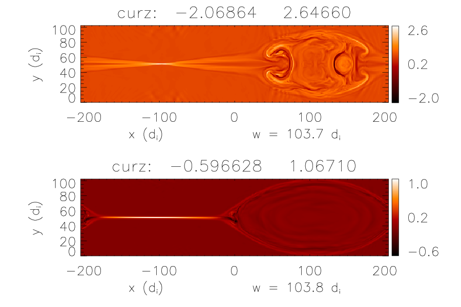
The out of plane current density, , is shown at late time in Fig. 2 for the runs corresponding to the two solid curves in Fig. 1. The top plot corresponds to the thick solid curve. The current sheet is short and opens wide, as is expected in Hall reconnection Shay et al. 1999; Horiuchi and Sato 1997; Pritchett 2001; Kuznetsova et al. 2001; Hesse et al. 2001; Porcelli et al. 2002. The bottom plot corresponds to the thin solid curve. The current sheet is long and thin as is expected from the SP theory of resistive reconnection Biskamp 1986; Uzdensky and Kulsrud 2000; Jemella et al. 2004. Since the same equations govern the two sets of data and the value of the resistivity is the same, we conclude that the system is bistable.

To complete the mapping of the two reconnection solutions, we vary the resistivities of the benchmark Hall and SP reconnection solutions of Fig. 1. For the case of Hall reconnection, corresponding to the thick solid line in Fig. 1, we change from 0.0 to 0.010, 0.013, 0.015, 0.0175, 0.020, 0.0225, 0.025 and 0.030 when . For the case of SP reconnection, corresponding to the thin solid line in Fig. 1, we change from to 0.003, 0.007, 0.009, 0.011, 0.013, 0.0175, 0.020, 0.0225, 0.025 and 0.030 when (after the Hall and electron-inertial terms have been re-enabled). The asymptotic reconnection rate is computed as the time averaged reconnection rate once transients have died away.
The results are plotted in Fig. 3(a), with the states starting from Hall reconnection plotted as open circles and the states starting from SP plotted as closed circles. The closed circles reveal that the disappearance of the SP solution occurs abruptly, with between 0.011 and 0.013. The open circles reveal the disappearance of the Hall reconnection configuration, with between 0.020 and 0.0225. The error bars are due to random fluctuations in the reconnection rate. The plot is reminiscent of what one would expect of a bifurcation diagram for a system with a cusp catastrophe.

Thus, the numerical simulations confirm that magnetic reconnection is bistable over a range of resistivity consistent with the scaling law predictions of and . The asymptotic steady state current sheet width , calculated as the half width at half maximum of at the X-line, is plotted in Fig. 3(b) for each of the runs. As predicted by Eq. (1), the steady state SP current sheet width is of order when the resistive reconnection solution ceases to exist, as is shown by the closed circles of Fig. 3(b).
We emphasize that the results presented in Fig. 3, though generated by a specific numerical procedure, are not sensitive to the details of this procedure. To demonstrate this, we show that the key feature of Fig. 3, the boundary where the slow reconnection solution disappears can be reproduced through a hysteresis-like procedure: in the simulation corresponding to the thin solid line in Fig. 1, we first lower the resistivity from to (when the island width is about ). As expected from Fig. 3 and shown in Fig. 4, the transition from SP to Hall reconnection occurs. We then raise the resistivity back to (the original value) when the island width is about . As can be seen in Fig. 4, fast reconnection continues, showing that the system can be in either of two steady states for the same set of parameters.
Having verified that reconnection is bistable with Hall MHD simulations, we return to the onset problem. We can compare the critical resistivity (or temperature, using the classical Spitzer formula) with observations of onset in physical systems such as solar eruptions and sawtooth crashes. For solar flares, and Miller et al. 1997, so from Eq. (3), in cgs units, corresponding to a temperature of . This is in excellent agreement with the coronal temperature.
For the sawtooth crash, the relevant kinetic scale is instead of because of the presence of a large guide field. If we assume that Eq. (1) can be carried over to the guide field case, we can make a comparison for sawtooth crash onset. Typical parameters for sawteeth in the DIII-D tokamak Lazarus 2005 are and and , where is the angular extent of the current layer Zakharov et al. 1993. For bean-shaped flux surfaces, the helical field strength in the plasma core is , so using Eq. (3) with in place of yields corresponding to . This temperature is an order of magnitude too small. However, the inclusion of diamagnetic effects Levinton et al. 1994, which are known to slow reconnection, should improve agreement. In future work we will explore whether Eq. (1) does hold in the presence of a guide field, for which is the relevant kinetic length scale.
The effect of collisionality on the reconnection rate was recently explored in the Magnetic Reconnection Experiment (MRX) Trintchouk et al. 2003. A sharp increase in the reconnection rate was observed at low collisionality, consistent with the qualitative picture presented here. Data for the current sheet width is unavailable, so quantitative comparisons are not possible at this time. Further, in this experiment fast reconnection has been correlated with magnetic turbulence localized in the reconnection layer Ji et al. 2004. Since the present simulations are limited to 2-D we can not address the development of this turbulence and how it might impact our conclusions. We surmise that our conclusions will not be strongly changed as long as the turbulence does not broaden the reconnection layer beyond the scale length .
We would like to thank two anonymous referees for helpful comments which made the presentation more clear. This work has been supported by NSF Grant No. PHY-0316197 and DOE Grant Nos. ER54197 and ER54784. Computations were carried out at the National Energy Research Scientific Computing Center.
References
- Sweet (1958) P. A. Sweet, in Electromagnetic Phenomena in Cosmical Physics, edited by B. Lehnert (Cambridge University Press, New York, 1958), p. 123.
- Parker (1957) E. N. Parker, J. Geophys. Res. 62, 509 (1957).
- Shay et al. (1999) M. A. Shay et al., Geophys. Res. Lett. 26, 2163 (1999).
- Birn et al. (2001) J. Birn et al., J. Geophys. Res. 106, 3715 (2001).
- Rogers et al. (2001) B. N. Rogers et al., Phys. Rev. Lett. 87, 195004 (2001).
- Oieroset et al. (2001) M. Oieroset et al., Nature 412, 414 (2001).
- Ren et al. (2005) Y. Ren et al., submitted for publication (2005).
- Hesse and Schindler (1986) M. Hesse and K. Schindler, Phys. Fluids 29, 2484 (1986).
- Lin et al. (2003) J. Lin et al., New Astron. Rev. 47, 53 (2003).
- Antiochos et al. (1999) S. K. Antiochos et al., Astrophys. J. 510, 485 (1999).
- Biskamp (2000) D. Biskamp, Magnetic Reconnection in Plasmas (Cambridge University Press, Cambridge, UK, 2000).
- Shay et al. (2004) M. A. Shay et al., Phys. Plasmas 11, 2199 (2004).
- Shay and Drake (1998) M. A. Shay and J. F. Drake, Geophys. Res. Lett. 25, 3759 (1998).
- Hesse et al. (1999) M. Hesse et al., Phys. Plasmas 5, 1781 (1999).
- Horiuchi and Sato (1997) R. Horiuchi and T. Sato, Phys. Plasmas 4, 277 (1997).
- Pritchett (2001) P. L. Pritchett, J. Geophys. Res. 106, 3783 (2001).
- Kuznetsova et al. (2001) M. M. Kuznetsova et al., J. Geophys. Res. 106, 3799 (2001).
- Hesse et al. (2001) M. Hesse et al., J. Geophys. Res. 106, 3721 (2001).
- Porcelli et al. (2002) F. Porcelli et al., Plasma Phys. Control. Fusion 44, B389 (2002).
- Biskamp (1986) D. Biskamp, Phys. Fluids 29, 1520 (1986).
- Uzdensky and Kulsrud (2000) D. A. Uzdensky and R. M. Kulsrud, Phys. Plasmas 7, 4018 (2000).
- Jemella et al. (2004) B. D. Jemella et al., Phys. Plasmas 11, 5668 (2004).
- Miller et al. (1997) J. A. Miller et al., J. Geophys. Res. 102, 14631 (1997).
- Lazarus (2005) E. A. Lazarus (2005), private communication.
- Zakharov et al. (1993) L. Zakharov et al., Phys. Fluids B 5, 2498 (1993).
- Levinton et al. (1994) F. M. Levinton et al., Phys. Rev. Lett. 72, 2895 (1994).
- Trintchouk et al. (2003) F. Trintchouk et al., Phys. Plasmas 10, 319 (2003).
- Ji et al. (2004) H. Ji et al., Phys. Rev. Lett. 92 (2004).