Autocatalytic chemical smoke rings
Abstract
Buoyant plumes, evolving free of boundary constraints, may develop well-defined mushroom shaped heads. In normal plumes, overturning flow in the head entrains less buoyant fluid from the surroundings as the head rises, robbing the plume of its driving force. We consider here a new type of plume in which the source of buoyancy is an autocatalytic chemical reaction. The reaction occurs at a sharp front which separates reactants from less dense products. In this type of plume, entrainment assists the reaction, producing new buoyancy which fuels an accelerating plume head. When the head has grown to a critical size, it detaches from the upwelling conduit, forming an accelerating, buoyant vortex ring. This vortex is analogous to a rising smoke ring. A second-generation head then develops at the point of detachment. Multiple generations of chemical vortex rings can detach from a single triggering event.
pacs
47.20.Bp, 47.70.FwHydrodynamic flows driven by chemical reactions have been studied since the discovery of fire, the oldest technology of humankind combust. Exothermic combustion reactions produce buoyant flames in the form of rising, reacting plumes and thermals which are often highly turbulent fires. In this Letter we examine a much simpler, yet still very rich, new system in which relatively gentle autocatalytic reaction fronts give rise to laminar plumes and thermals in the form of free vortex rings. Unlike conventional non-reacting plumes and thermals arising from localized heat sources, these flows have an internal source of buoyancy which is enhanced by subsequent entrainment, leading to flow acceleration similar to combustion. They provide a new and especially elegant model system in which to study instabilities in reacting flows.
Many autocatalytic chemical reactions exhibit sharp fronts. The well-studied reaction we employed was the iodate oxidation of arsenous acid hanna. The short range diffusion of the autocatalyst, here the iodide ion, limits the reaction to a very thin front separating reacted and unreacted solution. The front region of active reaction is typically only a few tens of microns thick, and is by far the smallest lengthscale in the system. Under gravity, hydrodynamic convection can be driven by buoyancy due to the density jump across the front. Density change is created both by thermal expansion due to the slight exothermicity of the reaction, and by the partial molal density decrease of the product solution pojman. Ascending fronts are hydrodynamically unstable because they put less dense products below denser unreacted solution hanna; pojman; vasquez_01; maser; wilder; huang; carey; bockmann; dewit; edwards; leconte.
In our plume experiments, we increase the viscosity of the water solution by adding glycerol. An ascending front is allowed to escape from a capillary tube into a much larger volume, so that boundaries no longer constrain the shape of the front. In the larger volume, a rising plume with a well-defined head is formed. During the early stages of the evolution of the head, its growth is due to both a volume flux of upwelling product solution and by the entrainment of reactant solution. Later, the plume head detaches and becomes a rising vortex ring, analogous to a chemically reacting smoke ring. The upwelling conduit that is left behind forms a new head which also eventually detaches, leading to generations of accelerating vortex rings. This surprising behaviour is in contrast to conventional buoyant vortex rings, which do not accelerate. It may have application as a laboratory analog of plumes in internally heated fluids, such as the Earth’s mantle mantle; griffiths_01.
The propagation of iodate-arsenous acid (IAA) reaction fronts has enjoyed considerable theoretical and experimental attention. It has been well-studied in capillary tubes pojman; vasquez_01; maser, in thin slots wilder; huang; carey; bockmann; dewit, and in the presence of a superposed flow edwards; leconte. In sufficiently narrow vertically oriented capillary tubes, convection is suppressed and the sharp reaction front is observed to propagate at constant speed in either direction. If the tube radius is increased beyond a critical size, the front deforms and upward propagation is accompanied by convection vasquez_02. Within a simple thin front approximation edwards, the relative importance of buoyancy is described by a dimensionless quantity
| (1) |
where is the acceleration due to gravity, is the kinematic viscosity, is the diffusion constant of the autocatalyst, and is the dimensionless density jump between the reacted () and unreacted () solutions. In practice, for the IAA reaction, . The critical tube radius for convection corresponds to a critical value . At slightly larger values , a transition to an axisymmetric mode of convection can be identified pojman. In the plume experiments described below, a very large tube was used, corresponding to .
In all previous studies of the IAA reaction hanna; pojman; vasquez_01; maser; wilder; huang; carey; bockmann; dewit; edwards; leconte, convection effects were severely constrained by the viscous interaction with nearby solid boundaries. We set out to find the reaction-driven flow phenomenology for an unbounded solution in which the reaction is initiated at a point, as nearly as possible. Two experimental difficulties immediately arise. For a water solution, the IAA reaction produces fronts that are sufficiently buoyant that the resulting plumes ascend quickly to the upper boundaries of any tank of managable size. These plumes also had Reynolds numbers, and therefore had a rather complex internal flow structure. We therefore explored the reaction in a water-glycerol solution in which the increased viscosity acts to limit the Reynolds number to , and to allow for an effectively longer evolution time within the experimental tank. These experiments reveal plumes with well-defined heads which eventually pinch-off to form essentially free vortex rings.
The second difficulty concerns initiating the front at a localized point. When the front is released from a very narrow capillary tube with diameter mm into a much larger volume, we found that the front did not propagate. This “front death” phenomenon front_death is apparently due to the requirement of a minimum critical concentration of autocatalyst near the initiation region, which therefore cannot be too small. To our knowledge, this effect has not been observed in the IAA reaction before. This constraint is easily overcome by using a large enough capillary tube to launch the reaction into the unbounded region. A diameter of mm proved to be sufficient.
Reactant solutions were prepared using reagent grade chemicals and distilled water with 40% glycerol by volume. Iodate stock solutions were prepared by dissolving powder in distilled water. Arsenous acid stock solutions were prepared from powder. These stock solutions were diluted so that the working solution contained []=0.005M and [As(III)]=0.020M. These concentrations were not varied in the experiments we report here. Congo red indicator was used to visualize the reaction fronts. Congo red has a pH range of 3.0 to 5.0, where the acid form is blue and the base form is red. The reaction front leaves in its wake a product solution with pH of so that the upwelling blue products are easily visible within the red unreacted solution.
The apparatus is shown in Fig. 1. The reaction tank was a large glass cylinder sealed by large rubber stoppers. A capillary tube entered through a hole in the lower stopper. The outside end of the capillary tube was sealed with a short rubber tube clamped at one end which formed the initiation volume. The rubber tube was filled by a porous plug made of loosely packed cotton. Reactions were initiated by inserting a thin needle into the rubber tube and then injecting a very small amount of product solution into the plug. The plug served to quench any hydrodynamic disturbance of the reactant solution during reaction initiation. The reaction proceeded up the capillary tube, which is large enough that and some convection is already present. It then escapes into the larger tank. The apparatus was illuminated from behind and still images of the evolving front were captured using a digital camera. The temperature was constant at C.

The various stages in the evolution of the resulting free autocatalytic plume are shown in Fig. 2. Initially the plume rises out of the capillary tube and its head remains roughly spherical and grows slowly. This stage of growth is shown in Fig. 2a. In this initial stage, there is essentially no entrainment of reactant solution into the plume head.
At a well-defined point, entrainment sets in. Fig. 2b shows a plume head well past the onset of entrainment. This shows the familiar mushroom-shaped head for a plume in which the surrounding fluid is being drawn into the head by a single overturning vortex ring.
Once the entraining autocatalytic plume head reaches a second critical size, the plume head begins to pinch-off from the upwelling conduit. The pinch creates a bottleneck in the conduit which then swells as it fills with rising product solution. During the swelling below the bottleneck, what was formerly the head of a starting plume becomes an essentially free vortex ring. As shown in Fig. 2c, the vortex ring detaches from the conduit, and is eventually connected only by a very thin filament of product solution. The swelling in the conduit develops into a new, second generation plume head. In Fig. 2d, a new pinch-off process has started again below the second generation plume head. Yet another bottleneck is formed when the second generation head pinches-off and becomes a vortex ring. The new bottleneck swells and the process is repeated. We have observed four generations of pinch-off and subsequent vortex ring formation in autocatalytic plumes. The fourth generation plume head eventually reaches the top boundary of the reaction vessel, closing the possibility of further pinch-off movie.
¿From the digital images of plume evolution, we determined the height and width of the ascending buoyant plume as a function of time. Height was measured from the top of the front to where it exited the capillary tube, and the width refers to the maximum width across the head or vortex ring. It is useful to define the dimensionless ratio , where is the width of the head and is the width of the conduit. Only the first generation head and vortex ring were considered in this analysis.
We found that the initial stage of growth ends and entrainment begins once reaches a critical value of . Similarly, once the entraining plume head reaches a second critical size, , the plume head begins to pinch-off from the upwelling conduit.

Typical width and height data for first generation head formation of an autocatalytic plume is shown in Fig. 3. We observed that the head accelerates during its ascent. The acceleration of the plume head continues after it has pinched-off, even though it is almost entirely disconnected from the conduit. This acceleration is in contrast to the constant velocity rise behavior previously observed in conventional plumes moses. The continued acceleration of the head once it pinches-off and becomes a thermal is also unique to autocatalytic plumes; normal vortex rings expand and slow down after they have pinched-off turner_01.
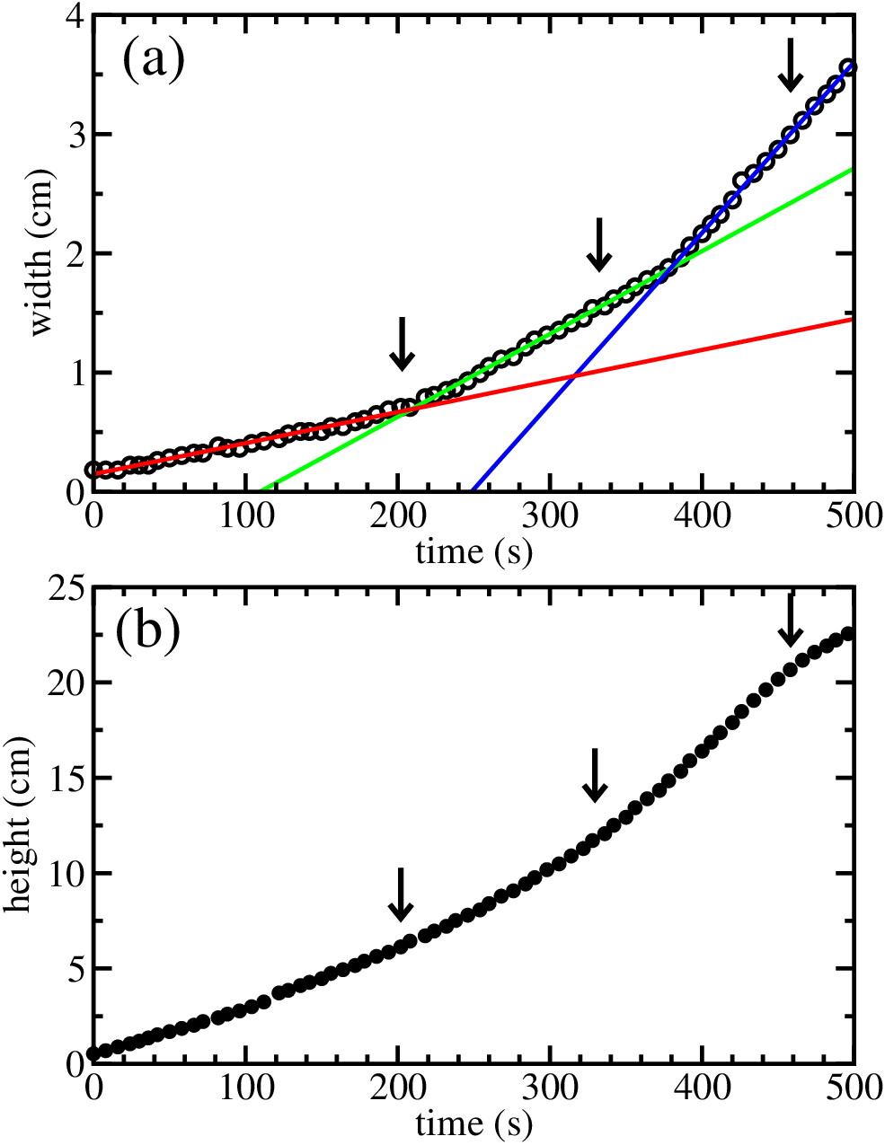
Fig. 3a shows that the width of the plume goes through three distinct regions of approximately linear growth. The initial, and slowest, growth rate obtains when and there is no entrainment into the plume head and it remains roughly spherical. A transition to a second, increased growth regime occurs once entrainment begins and . Finally, the third and fastest growth regime commences once and the plume head detaches and becomes a thermal. In experiments on conventional plumes the growth rate of the head has been determined moses to scale with time as , where . This is clearly not the case for autocatalytic plumes.
To our knowledge, our experiments mark the first study of buoyant plumes that are directly driven by an autocatalytic reaction. Of course, buoyant plumes moses; morton; turner_02; turner_03; griffiths_01 and buoyant vortex rings turner_01; turner_03; lundgren_01 have been the subjects of extensive previous study. Refs. fay; list; gebhart review much of the older work. Some clarification of nomenclature is useful here. A plume is a continuous region of buoyancy supplied by a point source. A starting plume is a plume with a well-defined, advancing head. These cases of buoyancy driven flow may be distinguished from a thermal, which is a freely evolving buoyant object disconnected from its source. Thermals may take the form of vortex rings, similar to smoke rings.
There is great diversity in past experiments on passive plumes, where we use passive to mean flows that do not react internally to produce buoyancy. In typical experiments, passive plumes are formed from buoyant fluid that has been injected into a less-buoyant medium at a point source. The buoyancy may be due to a temperature or composition difference or both. In this case, however, all the buoyancy is derived from processes external to the experiment and arrives with the volume of injected fluid. Subsequent stirring can only dilute and reduce this buoyancy. In the case of autocatalytic plumes, the volume of buoyant fluid injected is negligible and all of the buoyancy is generated by the conversion of dense fluid into buoyant fluid at the thin reaction front. The volume of buoyant fluid is steadily increasing, particularly in the head.
Symmetrical plume heads similar to those we observe can be found in passive starting plumes griffiths_01. Moreover, the heads of passive buoyant plumes can be observed to pinch-off to form buoyant thermals in the form of vortex rings. The formation thermals by pinch-off has been the subject of theoretical and of experimental interest in passive systems lundgren_02; fabris; gharib; shusser. The formation of discrete thermals is a characteristic of systems in which the ratio of the viscosities of the buoyant fluid and its surroundings is of order 1 jellinek.
There is a critical difference between the passive vortex rings formed by pinch-off and those that we observe in autocatalytic reactions. As the head or vortex ring rises, it entrains surrounding unreacted fluid, stirring it into the plume head and accelerating the production of new buoyancy. This feedback mechanism is unique to autocatalytic plumes. In our plumes, this stirring is laminar, rather than turbulent, and presumably involves the extreme stretching of the thin reaction front within the vortex ring.
Autocatalytic plumes may have a useful analogy to important geophysical processes. Conventional plumes have been the subject of numerous laboratory analog experiments aimed at understanding how material upwelling from deep in the mantle forms oceanic and continental hotspots griffiths_01. In addition to plumes, instabilities in the bottom layer of the mantle are also likely to give rise to thermals. Such thermals may incorporate internal sources of buoyancy due to the heat supplied by the breakdown of radionuclides. Internally heated thermals are one plausible explanation for ocean island volcanism griffiths_02. The buoyancy-producing capabilities of autocatalytic thermals could serve as an interesting laboratory analog of this process.
We have described a study of buoyant, three-dimensional plumes driven by the iodate-arsenous acid reaction. In a water solution that was made more viscous with the addition of glycerol, we found that a rising plume with a well-defined head was formed. The plume head grew to a critical size and subsequently detached from the upwelling conduit to form a buoyant vortex ring. The entrainment of reactant solution into the autocatalytic chemical plume head and subsequent vortex ring produced additional buoyancy by assisting the chemical reaction, leading to an acceleration of the vortex ring. This behavior reverses the usual role of entrainment, which normally acts to reduce buoyancy in conventional passive plumes and thermals. Autocatalytic chemical smoke rings offer some simple insights into combustion-driven flow and certain geophysical processes.
We thank M. Menzinger, A. De Wit, and A. M. Jellinek for helpful discussions and constructive comments. This research was supported by the Natural Science and Engineering Research Council of Canada.
References
- (1) J. Warnatz, U. Maas, and R.W. Dibble, Combustion, 3rd ed., Springer (2001).
- (2) S. R. Tieszen, Ann. Rev. Fluid Mech. 33, 67 (2001). 84, 4357 (2000).
- (3) A. Hanna, A. Saul, and K. Showalter, J. Am. Chem. Soc. 104, 3838 (1982).
- (4) J. A. Pojman, I. R. Epstein, T. J. McManus, and K. Showalter, J. Phys. Chem. 95, 1299 (1991).
- (5) D. Vasquez, J. Wilder, and B. Edwards, Phys. Fluids A 4, 2410 (1992).
- (6) J. W. Wilder, D. A. Vasquez and B. F. Edwards, Phys. Rev. E 47, 3761 (1993).
- (7) J. Huang, D. A. Vasquez, B. F. Edwards and P. Kolodner, Phys. Rev. E 48, 4378 (1993).
- (8) J. Maser, D. A. Vasquez, B. F. Edwards, J. W. Wilder and K. Showalter, J. Phys. Chem. 98, 6505 (1994).
- (9) M. R. Carey and S. W. Morris and P. Kolodner, Phys. Rev. E 53, 6012 (1996).
- (10) M. Bockmann and S. C. Müller, Phys. Rev. Lett. 85, 2506 (2000).
- (11) A. De Wit, Phys. Rev. Lett. 87, 054502 (2001).
- (12) B. F. Edwards, Phys. Rev. Lett. 89, 104501 (2002).
- (13) M. Leconte, J. Martin, N. Rakotomalala, and D. Salin, Phys. Rev. Lett. 90, 128302 (2003).
- (14) G.F. Davies, M.A. Richards, J. Geology, 100, 151 (1992).
- (15) R. W. Griffiths, I. H. Campbell, Earth Planet. Sci. Lett. 99, 66 (1990).
- (16) D. A. Vasquez, B. F. Edwards, and J. W. Wilder, Phys. Rev A 43, 6694 (1991).
- (17) E. Jakab, D. Horváth, J. H. Merkin, S. K. Scott, P. L. Simon and A Tóth, Phys. Rev. E., 66, 016207 (2002).
- (18)
For a movie of this process, see
http://www.physics.utoronto.ca/nonlinear/movies/plume.html - (19) E. Moses, G. Zocchi, A. Libchaber, J. Fluid. Mech. 251, 581 (1993).
- (20) J. S. Turner, Proc. R. Soc. Lond. A 239, 61 (1957).
- (21) B. R. Morton, G. Taylor, and J. S. Turner, Proc. R. Soc. Lond. A 234, 1 (1956).
- (22) J. S. Turner, J. Fluid. Mech. 13, 356 (1962).
- (23) J. S. Turner, Buoyancy Effects in Fluids, Cambridge University Press (1973).
- (24) T. S. Lundgren, N. N. Mansour, J. Fluid. Mech. 224, 177 (1991).
- (25) J. A. Fay, Ann. Rev. Fluid. Mech., 5, 151 (1973).
- (26) E. J. List, Ann. Rev. Fluid. Mech., 14, 189 (1982).
- (27) B. Gebhart, D. S. Hilder, M. Kelleher, Adv. Heat Transfer 16, 1 (1984).
- (28) T. S. Lundgren, J. Yao, N. N. Mansour, J. Fluid. Mech. 224, 177 (1992).
- (29) D. Fabris and D. Leipmann, Phys. Fluids 9, 2801 (1997).
- (30) M. Gharib, E. Rambod, and K. Shariff, J. Fluid Mech. 360, 121 (1998).
- (31) M. Shusser and M. Gharib, J. Fluid Mech. 416, 173 (2000).
- (32) A. M. Jellinek, A. Lenardic, M. Manga, Geophys. Res. Lett. 29, 10.1029/2001GL014624.
- (33) R. W. Griffiths, Earth Planet. Sci. Lett. 78, 435 (1986).