Studies of beam offset due to beam-beam interactions at a warm linear collider
At a warm linear collider the short time interval at which bunches
will pass near each other in the interaction region may lead to
significant alteration of the bunches positions.
In this paper we quantify
the intensity of this effect and show that it can be addressed by a fast intra-pulse feedback system.
To be submitted to Physical Review Special Topics, Accelerators and Beams
1 Beam-beam interaction and beam blow up at a warm linear collider
In a linear collider, near the interaction point (IP) after the final magnet the two beams are not any more shielded from each other by the beam pipe. Thus if the outgoing beam has been deflected vertically at the interaction point it will induce a vertical deflection of the incoming beam, leading to a loss of luminosity (see figure 1) and an increasing displacement of the beam along the train.
![[Uncaptioned image]](0411122v2/remaining_lumi.png)
|
|
Let the vertical offset of the -th electron (positron) bunch at the IP in units of the rms. beam size be () and define the relative offset by (we assume that the two beam have roughly the same size). Let the offsets without beam-beam interaction be . Then, the offsets with interaction are obtained successively by[1]
| (1) | |||
| (2) |
where is the horizontal (vertical) disruption parameter, the horizontal (longitudinal) bunch size, the crossing angle, the number of bunches that a given bunch sees on its journey from the last quad to the IP. The form factor is defined by
| (3) |
where is the classical electron radius, the number of particles in a bunch, the particle energy in units of rest mass and the beam deflection angle when the beam offset is , as shown on figure 2. (, when and .)
This number can be calculated using the following formula:
| (4) |
(here is the velocity of the beam taken as the velocity of the light in the calculations below).
![[Uncaptioned image]](0411122v2/deflection_angle.png)
|
|
An interesting point to note in this formula is that the offset is independent of the location at which bunch and cross each other. This happens because two different effects compensate each other. On the one hand the further away from the IP the crossing happens, the bigger the distance between bunches and is and thus the smaller the deflection angle of the bunch will be. But one the other hand, the distance traveled by the bunch after receiving this kick will be longer, thus making the offset at the IP bigger.
The simulations presented in this paper have been done using CAIN [2] with two sets of parameters, one close to the proposed parameters of the GLC (Global Linear Collider) and the other closer to the CLIC specifications. The parameters’ values used for these studies are adopted from the ITRC report [3] and are summarized in table 1.
| Set | GLC/NLC | CLIC |
|---|---|---|
| Energy (GeV) | 243 | 202 |
| (nm) | 243 | 202 |
| (nm) | 3 | 1.2 |
| (rad) | 27 | 24 |
| (m) | 110 | 35 |
| 0.16 | 0.04 | |
| 13.1 | 6.4 | |
| [eq 2] | 0.209 | 0.0213 |
| (crossing angle) (mrad) | 7 (20) | 20 |
| Bunch spacing (ns) | 1.4 | 0.67 |
| (distance between IP and last quad) (m) | 3.5 | 4.3 |
| N (bunches) [eq 4] | 16 | 42 |
2 Effect of the crossing angle and the other beam parameters on the beam blow up
The two parameters that have the biggest influence on the beam blow up are the crossing angle and the number (N) of outgoing bunches seen by an incoming bunch. The figure 3 shows how the blow up (simulated as described by equation 1) varies when the crossing angle varies from the smallest proposed value (7 mrad) to a much less challenging value (30 mrad) and the table 2 indicates the vertical offset of the last bunch of the train (It is assumed that is the same for all bunches of a train).
As one can see on this figure, for an initial offset of , even with a crossing angle of 7 mrad the maximum beam offset at the GLC due to the beam blow up does not exceed 3 . For a crossing angle of 10 mrad or more the beam offset remains below 1.6 . At CLIC the shorter bunch spacing increases the blow up effect. It can reach 23.9 for a crossing angle of 7 mrad and 5.3 for a crossing angle of 10 mrad. For wider crossing angle, the blow up remains below 2 . If the initial offset is bigger (5 or 10 ) then the final offset increases but the increase, which is related to the form factor shown on figure 2, is less than linear and the normalized offset () is smaller, as shown on figure 4).


| Crossing angle | offset | offset | offset | |||
|---|---|---|---|---|---|---|
| () (mrad) | GLC/NLC | CLIC | GLC/NLC | CLIC | GLC/NLC | CLIC |
| 7 | 2.6 | 23.9 | 8.7 | 28.7 | 14.9 | 33.8 |
| 10 | 1.6 | 6.4 | 6.5 | 14.1 | 12.2 | 20.8 |
| 15 | 1.2 | 2.2 | 5.6 | 7.8 | 10.9 | 14.0 |
| 20 | 1.1 | 1.5 | 5.3 | 6.3 | 10.5 | 12.1 |
| 30 | 1.0 | 1.2 | 5.1 | 5.6 | 10.2 | 10.9 |
To minimize the blowup effect it is better to locate the last quad closer to the IP but this is not desirable for the detector performance. Instead, it may be possible to keep the incoming and outgoing beam in separate pipes until they are very close from the IP, thus shielding them for each other’s influence and reducing N, the number of outgoing bunches seen by an incoming bunch (and thus the blow up).
On figure 5 one can see the influence of N (number of outgoing bunches seen by an incoming bunch) on the blow up. The offset of the last bunch of the train for various values of N is given in table 3. As shown previously, at very small crossing angle (7 mrad), the beam blow up is very important and thus the unshielded length has a strong influence on the total blow up. With such crossing angle reducing the unshielded length by 20 cm, from 4.2 m to 4.0 m can reduce the vertical offset of the last bunch of the train by more than for both the GLC and CLIC. At higher crossing angle (20 mrad), the beam blow up is much lower and thus the unshielded length has a smaller influence on the blow up.

| Number of | IR length (m) | 7 mrad | 20 mrad | |||
|---|---|---|---|---|---|---|
| bunches seen | GLC/NLC | CLIC | GLC/NLC | CLIC | GLC/NLC | CLIC |
| 0 | 1 | 1 | 1 | 1 | ||
| 10 | 1.8 | 2.3 | 1.1 | 1.1 | ||
| 16 | 2.6 | 4.2 | 1.1 | 1.2 | ||
| 30 | 7.1 | 14.3 | 1.2 | 1.3 | ||
| 40 | 12.0 | 22.4 | 1.3 | 1.5 | ||
| 42 | 13.0 | 23.9 | 1.3 | 1.5 | ||
3 Blow up and fast feedback system
Ground motion and other sources of vibrations may induce random changes in the beam offset from train. To reduce the luminosity lost due to this offset fast intra-pulse feedback systems have been proposed for the GLC (and the NLC)[4, 5, 6] to correct the beam offset by measuring the offset of the deflected outgoing pulses with a beam position monitor (BPM) and correcting the incoming pulses with a kicker. After initial correction a delay loop acts to prevent the system from forgetting the correction already applied.
As the beam blow up also results in a beam offset, the fast intrapulse feedback systems can also deal with it.
Mathematically the effect () of the feedback system described in [4] on bunch can be described as follow:
| (5) | |||||
| (6) | |||||
| (7) |
Where is the initial offset of the -th bunch (as defined above), is the relative angle with which bunch was deflected (F is shown on figure 2), is the latency of the system (that is the distance separating the BPM of the feedback system from the kicker plus the electronic latency, expressed in number of bunches), is the gain of the system (typically 0.6 for the GLC in normal conditions) and is the correction specific to bunch to which the correction (memorized by the delay loop) is added to give , the total correction to be applied.
This correction is directly subtracted from before computing the effect of the beam beam blow up as shown on equation 1. The electronic circuit of the system described in [4] is shown on figure 6.
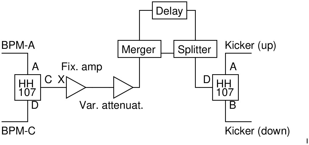
The effect of the beam blow up on the performance of these fast intra-pulse feedback systems is shown on figure 7. As one can see when the crossing angle is wide and thus blow up is not too intense (10 mrad and more for the GLC, 20 mrad and more for CLIC), the fast feedback system can correct the beam blow up whereas for smaller crossing angles the blow up drives the feedback system into oscillations between over-correction and under-correction.

These oscillations come from the delay between the time at which a correction is applied and the time at which the BPM measures the effects of this correction. Thus after correcting for a given effect the system still measure “uncorrected” bunches. This delay is induced by the time of flight from the kicker to the BPM and by the latency of the electronics used. The figure 8 shows that these oscillations appear regardless of the position of the fast feedback system (or the latency induced by the electronics), but their intensity increases when the system is located further away from the IP.

The delay loop of the fast feedback system (see figure 6) addresses some of the problems created by the system’s latency but it slows the capacity of the system to adapt to changing conditions such as those created by the beam blow up.
Thus to avoid the oscillations in the fast feedback system, one needs to add a second component to the correction predicted by the feedback system. The intensity of this second component must be directly proportional to the measured bunch position and should not be included in the delay loop. A modified feedback system including this second component is shown on figure 9.

Mathematically this new circuit requires the addition of a new term to equation 7 to compute the correction :
| (8) | |||||
| (9) | |||||
| (10) | |||||
| (11) | |||||
| (12) |
Where is the correction to be applied and is a proportionality coefficient (the gain of the feedback branch). The only difference between and is that the later is not included in the recursive term .
The performances of this modified circuit are shown on figure 10. The gains used for these numerical simulations are and for the GLC with a crossing angle of 7 mrad, and for CLIC at the same crossing angle. With a crossing angle of 10 mrad these values become / (GLC) and / (CLIC). These values have been obtained by tuning the system to minimize the luminosity loss. The ratio between these two values reflects the contribution of the beam blow up to the total beam offset. As one can see this modification cancels or reduces the luminosity loss due to the blow up.

4 Blow up correction based only on the first bunch measurement
As the offset of each bunch of the train is only affected by events (ground motion, transverse long-range wakefield, compensation error of beam-loading,…) that are known once the first bunch of the train reaches the IP, the correction to be applied to each bunch can be predicted once the offset of the first bunch is known. This property could be used to design a system that would compute the correction to be applied to each bunch based mainly on the measurement of the offset of the first bunch of the train. To cope with residual ground motion, a simple feedback system (without delay loop) must be added to this system. As the correction to be applied as a function of the bunch offset is not linear such system would have to be tuned for a given offset at which it would perform the best. The simple feedback loop would then perform the second order adjustments to remove the residual beam offset. By using switches it would be possible to switch between different sets of gains tuned for different initial offsets. The figure 11 shows an example of circuit (without switch) that could be used to implement such system. The figure 12 shows the performances of such circuit.
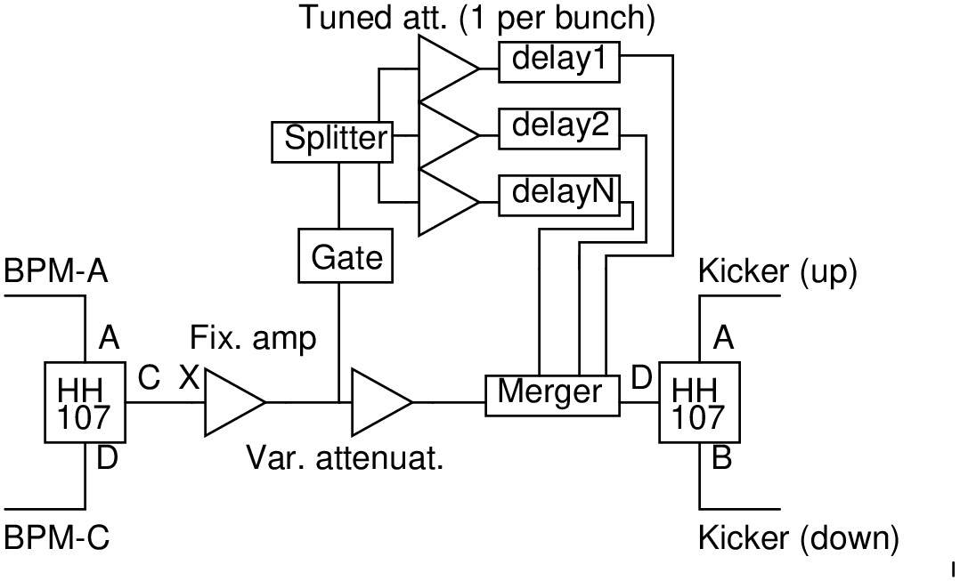

As one can see the performances of such system are rather attractive but the number of attenuators and wires required would be proportional to the number of bunches times the number of switches needed (as each of the bunches would require its own circuit). This huge number of wires needed might be a problem as it would increase the amount of dead material in the detector.
It is important to stress that in the two models presented in the previous section and the one in this section only analog electronics have been used but by the date at which the linear collider will be built very fast digital electronics will probably be available allowing a better correction of the end of the train.
5 Conclusion
The beam beam interactions at a warm linear collider such as the GLC or CLIC will create a blow up of the beam, especially at low crossing angle. If the crossing angle is wide enough then the blow up will be corrected by the fast intra-pulse feedback system. For smaller crossing angle the blow up will interfere with the feedback system but minor modifications of the feedback system will remove these interferences and correct the beam blow up.
6 Acknowledgements
One of the authors (ND) would like to thank JSPS for funding his stay in Japan under contract P02794.
References
- [1] Kaoru Yokoya and Pisin Chen. Beam-beam phenomena in linear colliders. Lecture at 1990 US-CERN School on Particle Accelerators, Hilton Head Isl., So. Carolina, Nov 7-14, 1990.
- [2] P. Chen, G. Horton-Smith, T. Ohgaki, A. W. Weidemann, and K. Yokoya. CAIN: Conglomerat d’ABEL et d’interactions nonlineaires. Nucl. Instrum. Meth., A355p107–110, (1995).
- [3] International Linear Collider Technical Review Committee. Second report, 2003. SLAC-R-606.
- [4] Nicolas Delerue. FEATHER: A fast intra-pulse feedback system for the JLC. (2003), physics/0305017.
- [5] D. Schulte. Simulation of an intra-pulse interaction point feedback for future linear colliders. eConf, C000821pMOA02, (2000), physics/0008128.
- [6] P. N. Burrows. Optimising the linear collider luminosity: Feedback on nanosecond timescales. eConf, C010630pT105, (2001), physics/0112080.