Extension and its characteristics of ECRH plasma in the LHD
Abstract
One of the main objectives of the LHD is to extend the plasma confinement database for helical systems and to demonstrate such extended plasma confinement properties to be sustained in steady state. Among the various plasma parameter regimes, the study of confinement properties in the collisionless regime is of particular importance. Electron cyclotron resonance heating (ECRH) has been extensively used for these confinement studies of the LHD plasma from the initial operation. The system optimizations including the modification of the transmission and antenna system are performed with the special emphasis on the local heating properties. As the result, central electron temperature of more than 10 keV with the electron density of 0.6 1019 m-3 is achieved near the magnetic axis. The electron temperature profile is characterized by a steep gradient similar to those of an internal transport barrier observed in tokamaks and stellarators. 168 GHz ECRH system demonstrated efficient heating at over the density more than 1.0 1020 m-3. CW ECRH system is successfully operated to sustain 756 s discharge.
pacs
00.00, 20.00, 42.101 Introduction
Electron cyclotron resonance heating (ECRH) plasmas have been extensively used for the confinement study from the initial operation of the LHD, where, extending the plasma confinement database of helical systems and demonstrating real steady state plasma confinement are its main subjects [1, 2].
Recently, the ECRH system is upgraded to operate four 168 GHz, two 84 GHz, and two 82.7 GHz gyrotrons, simultaneously. An 84 GHz CPD diode CW gyrotron with diamond window is also operated to perform long pulse discharge. As the result of system optimizations, including those of injection focal points, and polarizations, central electron temperature of more than 10 keV with the electron density of 0.6 1019 m-3 is achieved near the magnetic axis[3]. The electron temperature profile is characterized by a steep gradient similar to those of an internal transport barrier (ITB) observed in tokamaks and stellarators. The extension of the plasma parameter in such low collisional regime accelerated the study on the structure formation of the electron temperature and its relation to the radial electric field expected from neoclassical transport theory and resultant ITB in the LHD[4].
Opposite direction to the low density high temperature ECRH is high density heating. The effect of heating is confirmed up to the 1.5 1020 m-3 . Second harmonic ECRH at 168 GHz is proven to be effective for such high density, where the fundamental ECRH at 84 GHz is not accessible due to the cutoff.
Continuous or the long time sustainment of the plasma is another important missions for the LHD. The ECRH system is upgraded to demonstrate the continuous plasma sustainment in LHD. This upgrade includes setting and operation of 84 GHz CW gyrotron, the enforcement of the cooling for the waveguide transmission line, and installation of a waveguide antenna system. Injection of about 70 kW demonstrated that the plasma with the time and line averaged density of 2.4 1017 m-3 could be sustained for more than 750 sec.
2 Electron Cyclotron Heating System in LHD
Bird eye’s view of ECH system in LHD operated during last experimental campaign is shown in Fig. 1.
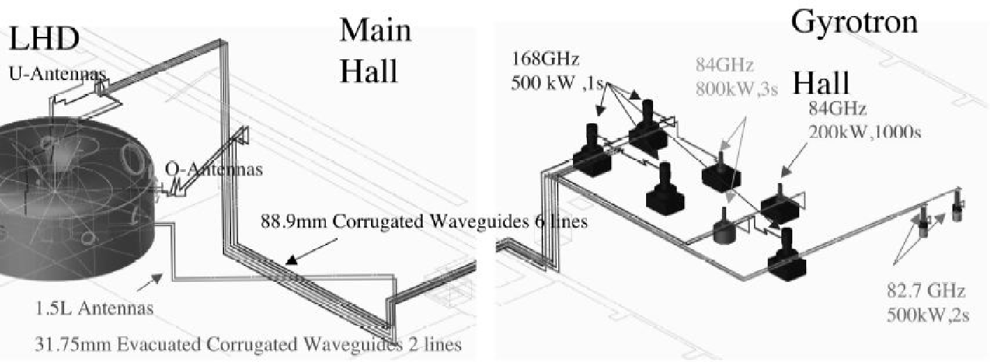
Six transmission lines of 88.9 mm id and two of 31.75 mm id corrugated waveguide, with total length of about 100 meters for each are in operational [6, 7].
| Gyrotron No. | # 1 | # 2 | # 3 | # 7 | # 4 | # 5 | # 11 | # 12 |
|---|---|---|---|---|---|---|---|---|
| freq. (GHz) | 168 | 168 | 168 | 168 | 84 | 84 | 82.7 | 82.7 |
| manufacturer | Toshiba | Toshiba | Toshiba | Toshiba | Gycom | Gycom | Gycom | Gycom |
| Triode | Triode | Triode | Triode | Diode | Diode | Diode | Diode | |
| spec. power (kW) | 500 | 500 | 500 | 500 | 800 | 800 | 500 | 500 |
| pulse width (s) | 1 | 1 | 1 | 1 | 3 | 3 | 2 | 2 |
| Power Supply | #1 CPD | #1 CPD | #1 CPD | #3 CPD | #2 CPD | #2 CPD | Non CPD | Non CPD |
| waveguide dia.(mm) | 88.9 | 88.9 | 88.9 | 88.9 | 31.75 | 31.75 | 88.9 | 88.9 |
| dry air | dry air | dry air | dry air | evacuated | evacuated | dry air | dry air | |
| total length (m) | 92 | 92 | 78 | 94 | 65 | 72 | 116 | 115 |
| No. of Bends | 18 | 21 | 16 | 21 | 10 | 10 | 19 | 15 |
| Max. Pin (kW) | 180 | 212 | 186 | 160 | 383 | 408 | 254 | 286 |
| Max. width (s) | 1.0 | 1.0 | 1.0 | 0.9 | 1.5 | 1.5 | 1.5 | 1.5 |
| Loss at MOU (%) | 23.0 | 24.0 | 14.0 | 32.8 | 10.0 | 10.0 | 8.5 | 6.5 |
| Trans. Efficiency (%) | 69.1 | 85.8 | 84.8 | 79.9 | 66.7 | 66.7 | 95.6 | 89.3 |
In Table 1 are also shown the power loss rate at the MOU and transmission efficiency for each line. It should be noted that the transmission efficiency for #11 and #12 are almost 90 %, although the number of miter bends and total path length are large. After this optimization, the threshold power for the arcing inside the waveguide appreciably increased. Relatively low efficiency for 168 GHz systems (#1-3,#7) and scatter of the values may be due to the sensitivity of the alignment of the input beam axis to that of waveguide. Low transmission efficiency for 31.75 mm diameter evacuated waveguides (#4 and #5) may be attributed to the low purity of the coupled HE11 mode. Since the axis alignment is less critical in the small diameter waveguide system, further optimization of the MOU mirrors or adjustment of the position of the waveguide mouth might be necessary. The power from each gyrotron is transmitted through a corrugated waveguide system and injected by a quasi-optical antenna system. Two sets of U (upper ) port antenna consist of two sets of mirrors for 82.7 and 168 GHz. The antenna mirrors are designed using the phase constant method assuming Gaussian optics[8]. Designed beam waist sizes on the mid-plane of LHD are 15 and 50 mm in radial and toroidal directions, respectively. These values and its steerability on the mid-plane of the LHD are confirmed by low power test. In each antenna system, final plasma facing mirror is plane mirror and can be steered by remote-controlled super sonic motors around two axis ( azimuth and elevation angle ).
Due to the complexity of the configurations of the transmission system, quasi-optical antenna system, the optimum setting of the antenna angles and polarizer rotation angles are not straightforward. Furthermore, the definition of the injection parameters on the frame of the LHD magnetic configuration is necessary and the actual quick selection and setting of these angles are required depending on the various experimental purposes. In order to perform effective local heating by the electron cyclotron waves, it is necessary to select more effective heating mode on the resonance between two eigen modes in the plasma. Desired polarization state to excite the effective mode is determined by the angle between injection and magnetic field directions at the interface of the injected beam to the plasma. The polarization state at the interface is controlled by the combination of rotation angles of two polarizers and antenna angles. Given the magnetic field configuration and the magnetic field strength, the optimum antenna setting angles can be determined using a geometrical configuration of the steering antenna. Once the injection angle of the beam is determined, the local magnetic field strength and the angle between injection and magnetic field direction at the interface of the plasma can be calculated. Using such derived magnetic field strength, the angle and the mode, the necessary polarization state can be calculated by the cold plasma dispersion relation. This polarization state is projected back to the polarizers to determine the best combination of the two polarizers.
a)
b)

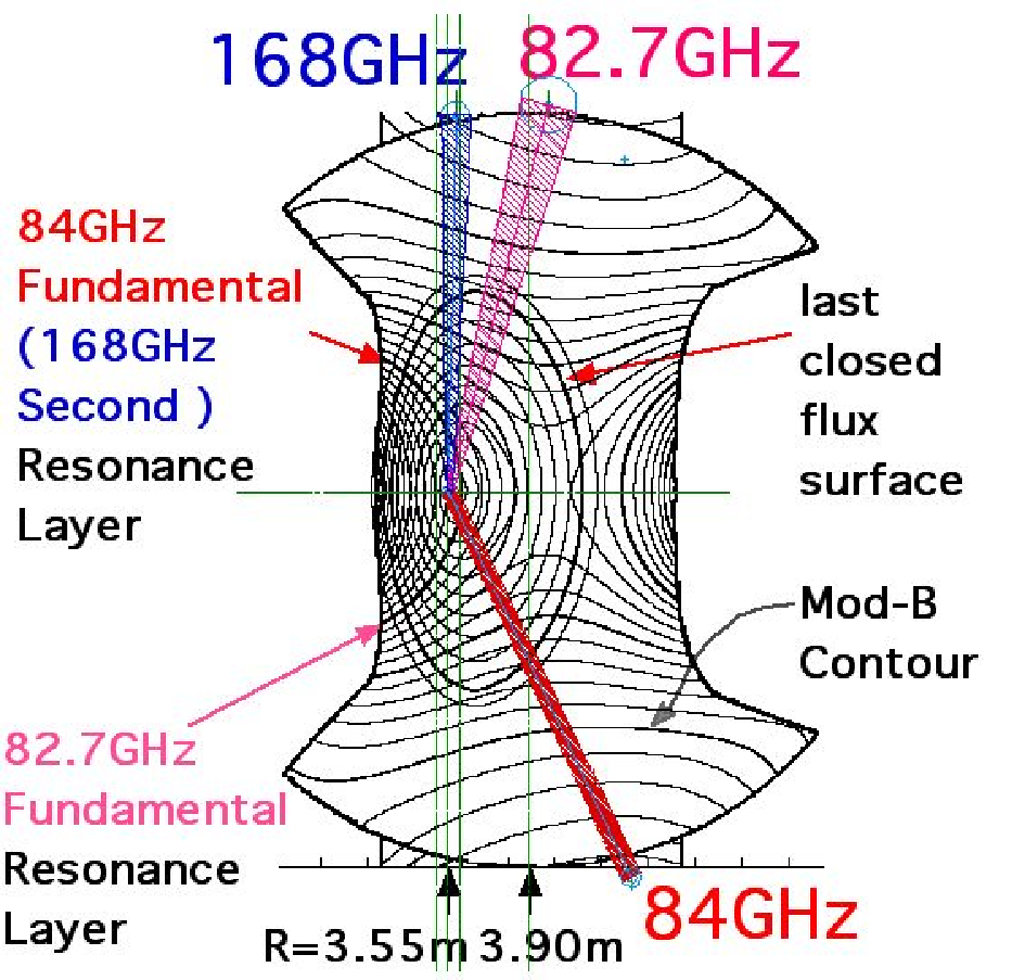
Fig. 2 a) shows the injection beams, mod-B contours, and flux surfaces in the vertically elongated poloidal cross section. Two sets of upper beams, one lower beam from a vertical antenna, and two beams from horizontal antennas are used. In order to attain high electron temperature at center, the magnetic field strength and the confinement magnetic field configuration are selected to have a power deposition as nearly on-axis as possible. One of the optimum combinations is the magnetic axis at 3.53 m and the toroidally averaged magnetic field strength on the axis at 2.951 T. The expected power deposition profile estimated by ray tracing code, including the weakly relativistic effect[9, 10], indicates that almost all of the injected power from the upper and lower antennas are concentrated within an averaged minor radius of 0.2 as shown in Fig. 2 b) , here, three cases of different injection angle is plotted to see the allowances and errors in antenna setting. Lower traces are integrated absorption power. Almost 100% power absorption can be expected in the density, and temperature regime discussed in this paper, provided that the beams crosses the resonance in the plasma confinement region and proper injection polarization state is selected.
3 Low collisionality regime
The magnetic field at the magnetic axis is effectively increased by shifting the axis inward (Raxis=3.5 - 3.6) from the standard position( Raxis= 3.75 m ) to locate the cyclotron layer across the axis. The injection beam aligned carefully, to hit the resonance on the magnetic axis. As a result, ECH beams were concentrated near the shifted axis. For the on-axis heating, strongly focussed Gaussian beams at the fundamental and second harmonic resonances are directed to the resonances near the magnetic axis. The microwave sources used in this case were 84 GHz, two 82.7 GHz, and three 168 GHz gyrotrons. Fig. 2 shows the injection beams, Mod-B contours, and flux surfaces in the vertically elongated poloidal cross section. Two sets of upper and one lower beams from a vertical antenna, and two beams from horizontal antennas are used. The magnetic field strength and the configuration are selected to have power deposition as nearly on-axis as possible. The selected magnetic axis is 3.53 m and the toroidally averaged magnetic field strength on the axis is 2.951 T. The expected power deposition profile is shown in Fig. 2.


Fig. 4 a) shows the evolution of plasma parameters and temperature profiles when the central electron Te0 exceeded 10 keV. The time evolution of the injected total power, the electron density, and the stored energy are shown here for the shot when the highest central electron temperature is recorded in the LHD. Almost 1.2 MW ECH power is concentrated inside 0.2. The electron density is slightly increasing but stays 0.5 to 0.6 1019m-3 in this case.
The two 84 GHz gyrotrons injected 0.7 MW to produce and heat the plasma. After the density and the stored energy had attained a quasi- steady state, the 168 GHz and 82.7 GHz power are added simultaneously. Although no additional gas puff is supplied, the density keeps increasing slightly. A high power YAG-Thomson scattering system is used at the times indicated by the arrows in Fig. 4 a). The profile is already sharp in the phase when only the 84 GHz power is injected. The 82.7 GHz power raises the central electron temperature to more than 10 keV. These high electron temperature modes appear only when the injected power exceeds a certain threshold level, and this threshold level increases with the electron density. Figure 4 shows the dependence of the local electron temperature at = 0, 0.2, 0.4 and 0.6 on the averaged electron density under the same injection condition. Since the expected power deposition and the deposition profiles do not change significantly, the sharp increase in the electron temperature at = 0, 0.2 suggests the presence of some non-linear mechanism. The feet of the ITB are more prominent when the ECH is applied on counter NBI target plasma. It is clear that the threshold power depends on the electron density. Other observations with respect to the ITB are as follows: 1) The power deposition profile plays an important role in the formation of the ITB. The total deposited power inside 0.2 seems the key factor. 2) Reduction of the ion and impurity transport after the ITB formation are suggested from impurity observations. indicates the presence of a positive electric field. 3) The location of the feet of the ITB depends on the direction of the NBI, which may be related to the position of the rational surface = 0.5[12]. The =0.5 surface plays an important role in expanding this interface outside. The clear ITB or foot point near = 0.2 to 0.3 is observed in the case of counter NBI as a target plasma for ECRH. The slope of the temperature profile gradually increases and clear foot point disappears in the case of co-NBI. 4) The density and electron temperature region of electron root predicted from neoclassical theory coincides with the region where the ITB appears.
These facts support the proposed anomalous transport reduction mechanism which the radial electric field shear reduces the fluctuation level and the shear itself is formed by the radial interface between electron and ion roots [5]. The details of the formation of the ITB is under study using heat pulse propagation. Here, the ITB is formed mainly by high power fundamental heating (84 and 82.7 GHz ) and the modulated second harmonic heating is used as a perturbation source. The drastic difference in the transient transport between with and without ITB is observed. The time lag of the heat pulse propagation clearly changes across the ITB region. This analysis is also enabled by the optimization of the modulating 168 GHz injection parameter.
The forward and backward transitions between ITB and normal confinement occurred when a part of the ECRH power is turned off and on to cross the threshold power for the ITB[4]. The decay time of the central temperature just after crossing down the threshold power is apparently long and high temperature gradient is kept for 60 ms. On the other hand, the decay time is short when the ECRH power kept below threshold. When the power increased stepwise crossing the threshold, high temperature gradient region grows gradually and the temperature profile jumps to form ITB about 40 ms after the stepwise increase. These results suggest that the temperature gradient helps to lower the threshold power for ITB formation[14].
4 High Density ECH
Second harmonic high frequency ECH is attractive because of its high density limit. The second harmonic heating system at 168 GHz for 3 T has been prepared to perform high density plasma heating. Second harmonic heating has its advantage in the accessibility in the high density region. Clear and definite demonstration of the effect is the increase of stored energy at the high density above the cut off of 84 GHz fundamental heating. The cut off density of 84 GHz fundamental O mode is 0.88 1020 m-3 while that of 168 GHz second harmonic X mode is 1.75 1020 m-3. Actually, 168 GHz ECRH power is applied on the high density, high stored energy plasma and helped to sustain and push highest record value. In Fig. 6 a) is shown the wave forms of the shot where the highest stored energy is recorded in LHD. Three negative ion source NB are injected step by step and the repetitive pellet is injected to increase the density. The total injected NB power attained 9 MW in this shot. The line averaged density once reaches 2.0 1020 m-3 and decreases with the time constant of 0.5 s. The 168 GHz power of the level of 800 kW in total is applied on such high density plasma. dependence of heating efficiency of 168 GHz on target plasma density. The heating efficiency is estimated from the difference of the time derivative of stored energy just before and after the turning on and off time of 168 GHz pulse. Figure 6 b) shows such estimated heating efficiency as a function of line-averaged density. Difference of the mark corresponds to the timing of turing on and off for stored energy. Appreciable heating effect is observed for the shots of the averaged electron density above 1.0 1020 m-3. Although the degradation of the efficiency appears above 1.0 1020 m-3, heating efficiency of near 30% is observed near the right hand cutoff density of 1.75 1020 m-3. Highest efficiency point for 1.7 and 1.2 1020 m-3 just corresponds to the turn on and off data from Fig. 6 a). This figure clearly shows the effectiveness of second harmonic heating.


5 Long Pulse Operation
Demonstration of steady state high Te plasma sustainment is important from the view point of extending the helical magnetic confinement device to the fusion reactor. Technical issue in the CW ECH system is also important in the next step fusion device as ITER. Especially, the heat removal around gyrotron, MOU and transmission components are of critical issues. Development of low loss and safety component is required. Management of heat flux into the diverter and first wall, plasma density, temperature and particle control and sustainment in the steady state condition are to be established. A CW gyrotron with the diamond window at the frequency of 84 GHz is introduced to perform the steady state plasma sustainment in LHD. This gyrotron is connected to one of the evacuated corrugated waveguide systems of 31.75 mm id. (#5) listed in Table 1.
In order to monitor the temperature rise in the waveguide components, multi-point temperature measurement system is introduced and attached the sensors along the long transmission line. Since existing focusing antenna for this line had no cooling capability, a corrugated up taper from 31.75 mm id to 63.5 mm id is connected and the output beam is directed to a magnetic axis. Because of limited injection power, gas feed rate is controlled by repetitive pulse puff. Almost all gyrotron parameters stayed almost constant during 766 sec injection. Collector, body voltages are well controlled and kept constant during the shot. Beam and body current and little increases with the time constant of 300 s and then saturates to be constant toward the end of the pulse. Temperature difference between inlet and outlet of several channels of the gyrotron coolant are still a little increasing even after such long pulse operation, but demonstrated that this gyrotron can be operated more than 1000 s with the power level at 150 kW. Operation of the interlock on the pressure in the waveguides due to the excess outgas resulted from the temperature rise had been the major cause of the termination of the pulse. Out gassing were far from saturation and the pressure kept increased due to the poor conductance in the waveguide. Figure 6 shows time evolutions of a) injection power, b) averaged electron density, c) ECE radiation temperature, d) radiation power and e) temperature rise in waveguide component. The repetitive gas puff is controlled not to cause radiation collapse. This is the reason why the density, temperature and radiation fluctuates. In average, plasma with electron density of 2.4 1017 m-3, and ECE radiation temperature of 240 eV ( this is not necessarily the real electron temperature due optically thin) is sustained by 72 kW injection power. It is noted that the density decay rate just after the gas puffing pulse decreases towards the end of the pulse. This might reflect the change of recycling from the wall. It is necessary to continue the effort to increase the injection power by enforcing the cooling and pumping of the waveguide.
6 Conclusions
ECRH system have been upgraded step by step to inject total power more than 2 MW. The optimizations of the injection condition for almost all antennas are performed in the beam steering angle and also polarization. The power deposition profile is carefully controlled and utilized to achieve high electron temperature of more than 10 keV and formation of ITB. Sharp power deposition is also utilized in analyzing and understanding the transport mechanisms. Second harmonic heating of 168 GHz demonstrated effective heating at the density of more than 1.5 1020 m-3. Long pulse more than 12 minutes of 70 kW at 84 GHz is injected and sustained the plasma for 756 sec at the averaged density of 2.4 1017 m-3.
References
References
- [1] A. Iiyoshi, M. Fujiwara, O. Motojima et al, Fusion Technol. 17 (1990) 169.
- [2] O. Motojima, H. Yamada, A. Komori et al, Phys. Plasmas 6 (1999) 1843.
- [3] S. Kubo,et al, J. Plasma Fusion Res., 78 (2002) 99.
- [4] T. Shimozuma, S. Kubo, H. Idei, Y. Yoshimura, et al, Plasma Physics and Controlled Fusion 45 (2003) 1183.
- [5] A. Fujisawa, H. Iguchi, T. Minami, et al , Phys. Plasmas 7 (2000) 4152.
- [6] S. Kubo, et al Proc. Radio Frequency Power in Plasmas (1999) 485.
- [7] T. Shimozuma, et al Fusion Engineering and Design,53 (2001) 525.
- [8] S. Kubo, et al Fusion Engineering and Design 26 (1995) 319.
- [9] S. Kubo, et al Proc. 11th International Conf. on Plasma Phys. (2002).
- [10] M. Bornatici, et al, Nuclear Fusion, Vol. 23 (1983) 1153.
- [11] H. Idei, et al, Fusion Engineering and Design, 53 (2001) 329.
- [12] Y. Takeiri, T. Shimozuma, S. Kubo, et al, Phys. Plasmas 10 (2003) 1788.
- [13] S. Kubo, H. Idei, T. Notake, et al, J. Plasma Fusion Research SERIES, Vol. 5 (2002) 584.
- [14] M. Yokoyama, K. Ida, H. Sanuki, et al, Nucl. Fusion 42 (2002) 143.