Transparency of Magnetized Plasma at Cyclotron Frequency
Abstract
Electromagnetic radiation is strongly absorbed by the magnetized plasma if its frequency equals the cyclotron frequency of plasma electrons. It is demonstrated that absorption can be completely canceled in the presence of a second radiation beam, or even a magnetostatic field of an undulator, resulting in plasma transparency at the cyclotron frequency. This effect is reminiscent of the electromagnetically-induced transparency (EIT) of the three-level atomic systems, except that it occurs in a completely classical plasma. Also, because of the complexity of the classical plasma, index of refraction at cyclotron frequency differs from unity. Potential applications of the EIT in plasma include selective plasma heating, electromagnetic control of the index of refraction, and electron/ion acceleration.
Electromagnetically induced transparency (EIT) in quantum-mechanical atomic systems is a well understood and thoroughly studied [1] subject. EIT is the basis of several very important applications, such as slow light [3], information transfer between matter and light [4, 5], sound wave generation [6], or even testing of the black-hole physics [7]. Several recent reviews [2] illucidated the quantum mechanical mechanism of EIT which relies on the destructive interference between several pathways which connect the ground and excited states of the atom. The purpose of this Letter is to describe EIT in a classical plasma.
We consider an externally magnetized plasma with and density . A right-hand polarized electromagnetic wave (which we refer to as the probe) at the frequency equal to cyclotron frequency cannot propagate in the plasma because it undergoes resonant cyclotron absorption [8]. The cold magnetized plasma dispersion relation v. s. for the right-hand polarized probe, plotted in Fig. 1, is given by . Plasma current and the wavenumber become infinite for , and a forbidden bandgap develops between and , where is the plasma frequency. This Letter demonstrates that by adding a second intense electromagnetic wave (pump) with frequency create a transparency near the cyclotron frequency. Moreover, if , transparency can be created by a magnetostatic undulator with arbitrary wavenumber .
The classical mechanism of the electromagnetically induced transparency is the destructive interference between the electric field of the probe and the sidebands of the electric and magnetic fields of the pump which are produced by the collective electron plasma oscillation with frequency along the magnetic field. Qualitatively, the total force at the cyclotron frequency experienced by a plasma electron is given by , where is the electron displacement in the plasma wave. If the pump, probe, and plasma waves are properly phased, then Therefore, if the amplitudes and phases of the pump and the plasma wave are properly correlated, then . Consequently, the plasma current at the cyclotron frequency is small (or even vanishing), and the probe propagates as if in vacuum. Our numerical simulation below demonstrates that this correlation is naturally achieved in a collisionless plasma.

We assume two right-hand polarized EM waves propagating along direction, with their electric and magnetic fields given by , , and , where , , , and . Non-relativistic equation of motion of a plasma electron in the combined field is given by
| (1) |
where and are the particle position and velocity, and the initial conditions are and . The third term in the lhs of Eq. (1) is the restoring force of the ions [9].
Equation (1) was integrated for two cases: (a) when only a probe field is turned on, and (b,c) when both the pump and the probe are turned on. The pump and the probe amplitudes were increased adiabatically in time, up to their respective peak amplitudes of and , according to
| (2) |
enabling the pump to turn on first, followed by the probe.
Simulation results for () are shown in Fig. 2. Without the pump electron is resonantly driven by the probe as shown in Fig. 2(a). In the plasma, this growth manifests itself in a large electron current and probe absorption because, time-averaged, . Adding a strong pump with and dramatically changes electron motion, see Fig. 2(b). After the pump is turned on but before the turning on of the probe, electron oscillates in the field of the pump according to . Switching on the probe does not significantly alter electron motion: is shown as a barely visible dashed line in Fig. 2(b)). Comparing Figs. 2(a) and (b), observe that the pump suppressed electron responce at the cyclotron frequency, making the plasma transparent to the probe.
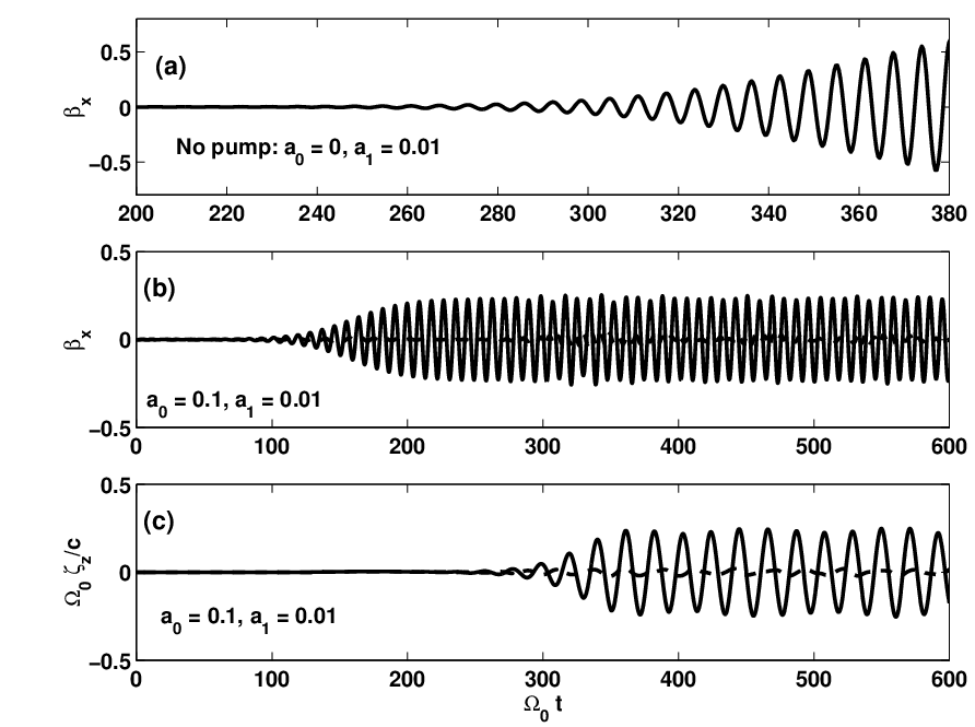
Suppression is caused by the excitation of a strong plasma [shown in Fig. 2(c)] which produced a sideband of the pump at the cyclotron frequency. This sideband canceled the electric field of the probe. An approximate analytic formula for the steady-state amplitude of the plasma oscillation,
| (3) |
is derived below by requiring that the sideband cancels the probe. which is in good agreement with the simulation result. Simulation results demonstrate stability of the steady-state values of and which are naturally reached in a collisionless plasma. Note that the pump has to be switched on prior to the arrival of the probe. In atomic physics, this pulse sequence is referred to as “counter-intuitive” [2].
Maintaining high-power pumping waves in the plasma may prove challenging in practice. For example, supporting over an area requires microwave power of megawatts. Fortunately, for , a magnetostatic helical undulator can replace a microwave beam. We simulated electron motion in the combined field of an undulator with and , and a probe which is switched on according to , where . Suppression of the electron responce at the cyclotron frequency is apparent from Fig. 3(a). Electric field of the probe is canceled by the force which is exerted on a longitudinal plasma wave by the helical magnetic field of the undulator.
Steady-state values of and can be analytically obtained by linearizing Eq. (1) in the weak probe limit.
| (4) |
Introducing and assuming that , exponentials in Eq. (4) are expanded as , yielding
| (5) |
Longitudinal equation of motion is given by
where was expanded as to first order in . Inserting the expression for , obtain
| (6) |
The last term in the RHS of Eq. (6) will be later dropped because it is proportional to the product of two small quantities, and . Note that, unlike the transverse velocity which is excited directly by each of the two lasers according to Eq. (5), plasma waves are excited only in the presense of two lasers via the beatwave mechanisms.
The physical reason for EIT in plasma is the strong coupling between longitudinal and transverse degrees of freedom of the plasma electrons. The steady-state solution of Eq. (6) , where and , is substituted into the transverse equation of motion (5). Retaining the terms with and dependence results in
| (7) |
Applying Eq. (7) to the simulated earlier case of and yields the steady-state amplitude of the plasma wave given by Eq. (3).
In the general case of we insert and into Eq. (6) yielding
| (8) |
where . Equation (8) is then solved for which is substituted into Eq. (7) yielding the steady-state value of :
| (9) |
where we have neglected terms proportional to the product of laser detuning from resonance and the pump intensity . Qualitatively, the pump influence is strong only close to the cyclotron resonance, and is negligible far from . From Eq. (9), plasma is resonantly driven when the denominator vanishes. Close to cyclotron resonance , where is the effective Rabi frequency. Hence, the modified plasma resonances are shifted from to .

Fluid velocity component proportional to is given by where .
Dispersion relation for classical EIT in magnetized plasma is derived from the wave equation for the probe , where the rhs is equal to :
| (10) |
where it was assumed that the frequency of the pump is fixed at . Complete transparency () is achieved at , where . Note that this frequency shift is in general very small in the most interesting regime of : , and can be even smaller near cyclotron resonance when pump and probe co-propagate. Equation (10) reduces to the dispersion relation for a single probe in magnetized plasma for large detunings . The influence of the pump is significant only in the vicinity of .
Note that index of refraction is not identically equal to unity at the cyclotron resonance. This is different from the quantum-mechanical result for a three-level system [11], where on resonance. It can be demonstrated that this difference occurs because multiple Landau levels and corresponding Raman-shifted levels participate in the classical EIT.
Dispersion relation given by Eq. (10) is plotted in Fig. (4) for the same plasma parameters as in Fig. (1), plus a co-propagating pump with . The flat band between the resonant frequencies is a novel feature which is not present without the pump (compare with Fig. (1)). The width of this EIT band proportional to can become very narrow for low pump amplitude. The corresponding “group velocity” (understood in a stricly geometrical sense explained below) can also be made arbitrarily small. Slowly propagating wavepacket of electromagnetic waves is a classical analog of the “slow light” in atomic systems [3].
Qualitatively, the spectacular slowing down of EM waves in the EIT plasma can be understood by considering the entrance of a probe beam of duration into the plasma. In steady state inside the plasma, the “slow light” wavepacket of length consists of the transversely polarized field of the probe and the longitudinal electric field of the plasma wave . As the pulse enters the plasma, it loses photons to the pump at the same rate as new plasmons are created (according to the Manley-Rowe relation). Classical photon density of a field with frequency is proportional to the action density , where is the energy density. We calculate that the ratio of the plasmon to photon density inside the “slow light” pulse,
| (11) |
is if . Thus, most photons of the original pulse are lost to the pump. Since the index of refraction remains close to unity, so is the photon energy density. Therefore, the loss of photons is due to the spatial shortening of the pulse from to . Because temporal pulse duration does not change, we recover the previously calculated . It is precisely in this geometric sense of that the group velocity of the slow light is interpreted. is not related to the speed of individual photons since their number is not conserved during the pulse transition into the plasma.

One interesting application of EIT in magnetized plasma is ion acceleration. While laser-plasma accelerators of electrons [12] have long been considered as a long-term alternative to conventional rf cavity-based linacs, the field of plasma-based ion accelerators is still in its infancy [13]. EIT enables one to conceive a short-pulse ion accelerator which consists of a “slow light” pulse in plasma with approximately equal group and phase velocities. Acceleration is accomplished by the longitudinal electric field of the plasma wave. Counter-propagating geometry is chosen to match the phase and group velocities because . Matching yields . Other types of accelerators based on the “slow light” which rely on the ponderomotive force also appear attractive because the ponderomotive force, which scales as the gradient of the energy density , increases rapidly with decreasing group velocity of the probe.
References
- [1] K. J. Boller, A. Imamoglu, and S. E. Harris, Phys. Rev. Lett. 66, 2593 (1991); S. E. Harris, Phys. Rev. Lett. 70, 552 (1993).
- [2] S. E. Harris, Physics Today 7, 36 (1997); J. P. Marangos, Journ. Modern Optics 45, 471 (1998); A. B. Matsko et. al., Advances in Atomic, Molecular, and Optical Physics 46, 191 (2001).
- [3] L. V. Hau et. al., Nature 397, 594 (2001).
- [4] M. Fleischhauer, S. F. Yelin, and M. D. Lukin, Opt. Commun. 179, 395 (2000).
- [5] M. D. Lukin, S. F. Yelin, and M. Fleischhauer, Phys. Rev. Lett. 84, 4232 (2000).
- [6] A. B. Matsko, Y. Rostovtsev, M. Fleischhauer, and M. O. Scully, Phys. Rev. Lett. 86, 2006 (2001).
- [7] U. Leonhard and P. Piwnicki, Phys. Rev. Lett. 84, 822 (2000).
- [8] N. A. Krall and A. W. Trivelpiece, Principles of Plasma Physics, Chapt. 4 (McGraw-Hill, New York, 1973).
- [9] J. Dawson, Phys. Rev. 113, 383 (1959).
- [10] M. N. Rosenbluth, C. S. Liu, Phys. Rev. Lett. 29, 701 (1972).
- [11] M. O. Scully, Phys. Rev. Lett. 67, 1855 (1991); M. Fleischhauer, C. H. Keitel, and M. O. Scully, Phys. Rev. A 46, 1468 (1992).
- [12] T. Tajima and J. M. Dawson, Phys. Rev. Lett. 43, 267 (1979).
- [13] R. A. Snavely et. al., Phys. Rev. Lett. 85, 2945 (2000).