41.60
Photon emission by ultra-relativistic positrons in crystalline undulators: the high-energy regime. submitted for the proceedings of the International Workshop on “Electron-Photon Interaction in Dense Media” in Nor-Hamberd, Armenia, 2001
Abstract
This paper discusses the undulator radiation emitted by high-energy positrons during planar channeling in periodically bent crystals. We demonstrate that the construction of the undulator for positrons with energies of 10 GeV and above is only possible if one takes into account the radiative energy losses. The frequency of the undulator radiation depends on the energy of the particle. Thus the decrease of the particle’s energy during the passage of the crystal should result in the destruction of the undulator radiation regime. However, we demonstrate that it is possible to avoid the destructive influence of the radiative losses on the frequency of the undulator radiation by the appropriate variation of the shape of the crystal channels. We also discuss a method by which, to our mind, it would be possible to prepare the crystal with the desired properties of its channels.
1 Introduction
We discuss a mechanism, initially proposed in Korol et al. 1998; Korol et al. 1999, for the generation of high-energy photons by means of planar channeling of ultra-relativistic positrons through a periodically bent crystal. In this system there appears, in addition to the well-known channeling radiation, an undulator type radiation due to the periodic motion of the channeling positrons which follow the bending of the crystallographic planes. The intensity and the characteristic frequencies of this undulator radiation can be easily varied by changing the positrons energy and the parameters of the crystal bending.

The mechanism of the photon emission by means of the crystalline undulator is illustrated in figure 1. It is important to stress that we consider the case when the amplitude of the bending is much larger than the interplanar spacing () of the crystal (), and, simultaneously, is much less than the period of the bending ().
In addition to the spontaneous photon emission the scheme leads to the possibility to generate stimulated emission. This is due to the fact, that the photons emitted at the points of maximum curvature of the trajectory travel almost parallel to the beam and thus, stimulate the photon generation in the vicinity of all successive maxima and minima of the trajectory.
The bending of the crystal can be achieved either dynamically or statically. In Korol et al. 1998; Korol et al. 1999 it was proposed to use a transverse acoustic wave to bend the crystal dynamically. The important feature of this scheme is that the time period of the acoustic wave is much larger than the time of flight of a bunch of positrons through the crystal and thus the crystal bending does not change on this time scale. One possibility to create acoustic waves in a crystal is to place a piezo sample atop the crystal and to use radio frequency to excite oscillations.
The usage of a statically and periodically bent crystal was discussed in Mikkelsen and Uggerhøj 2000. The idea is to construct a crystalline undulator based on graded strained layers. We will present a detailed description how a static crystalline undulator can be produced.
We now consider the conditions for stable channeling. The channeling process in a periodically bent crystal takes place if the maximum centrifugal force in the channel, ( being the minimum curvature radius of the bent channel), is less than the maximal force due to the interplanar field, which is equal to the maximum gradient of the interplanar field (see Korol et al. 1999). More specifically, the ratio has to be smaller than 0.15, otherwise the phase volume of channeling trajectories is too small (see also Korol et al. 2000). Thus, the inequality connects the energy of the particle, , the parameters of the bending (these enter through the quantity ), and the characteristics of the crystallographic plane.
A particle channeling in a crystal (straight or bent) undergoes scattering by electrons and nuclei of the crystal. These random collisions lead to a gradual increase of the particle energy associated with the transverse oscillations in the channel. As a result, the transverse energy at some distance from the entrance point exceeds the depth of the interplanar potential well, and the particle leaves the channel. The quantity is called the dechanneling length Gemmel 1974. To calculate one may follow the method described in Biruykov et al. 1996; Krause et al. 2000. Thus, to consider the undulator radiation formed in a crystalline undulator, it is meaningful to assume that the crystal length does not exceed .
In Krause et al. 2000 we estimated the parameters and for given energy , regarding the dechanneling length of the bent crystal and the reduction of the phase-space volume due to the bending. For 500 MeV positrons in Si(110) the optimal parameters are and cm. The spectral distribution of the emitted radiation in this case is discussed in the next section (see also Krause et al. 2000).
In the present paper we discuss the possibility to construct undulators to generate photons with energies larger than 1 MeV using positron energies above 10 GeV when the radiative energy losses cannot be neglected and, thus, must be taken into account Korol et al. 2000.
The frequency of photons generated in the undulator is determined by the energy of the projectiles and also by the undulator parameter (for definition see equation (1)). In the regime in which the energy of the projectiles is not constant during their passage through the undulator, the frequency of the emitted undulator radiation can nevertheless be kept constant if one chooses the appropriate variation of the shape of the undulator along its length.
We also discuss a method by which, to our mind, it would be possible to prepare crystals with the desired properties of their channels.
2 Spectra of the spontaneous emitted radiation
To illustrate the undulator radiation phenomenon, which we discuss, let us consider the spectra of spontaneous radiation emitted during the passage of positrons through periodically bent crystals.
The photon emission spectra have been calculated using the quasiclassical method Baier et al. 1998. The trajectories of the particles were calculated numerically and then the spectra were evaluated Krause et al. 2000. The latter include both radiation mechanisms, the undulator and the channeling radiation.
The spectral distributions of the total radiation emitted in forward direction for MeV positrons channeling in Si along the (110) crystallographic planes are plotted in figure 2. The wavelength of the crystal is fixed at cm, while the ratio is changed from 0 to 10. The length of the crystal is cm and corresponds to undulator periods.

The first graph in figure 2 corresponds to the case of the straight channel () and, hence, presents the spectral dependence of the ordinary channeling radiation only. Increasing the ratio leads to modifications in the spectrum of radiation. The changes which occur manifest themselves via three main features: the lowering of the ordinary channeling radiation peak, the gradual increase of the intensity of undulator radiation due to the crystal bending and the appearing of additional structure (the sub-peaks) in the vicinity of the first harmonic of the ordinary channeling radiation. A more detailed analysis of these spectra can be found in Krause et al. 2000.
To check our numerical method, we have calculated the spectrum of the pure channeling radiation for 6.7 GeV positrons in Si(110) integrated over the emission angles. Figure 3 shows the experimental data Bak et al. 1985; Uggerhøj 1993 and the results of our calculations, normalized to the experimental data in the vicinity of the second harmonic.

The energy and the spectral dependence of the calculated spectra is in good agreement with the experimental data. The fluctuations at high energies are an artifact of our numerical method. Increasing the number of calculated trajectories will reduce these fluctuations but also increase the computation time.
The height of the first harmonic is overestimated in our calculations. The calculations performed in Bak et al. 1985 give a similar result. This disagreement arises likely due to the neglection of multiple collisions both in our work and in Bak et al. 1985. The shape and the location of the first harmonic are described quite well. This fact demonstrates that the Molière potential is a good approximation for the interplanar potential, because the spectral distribution of the channeling radiation is highly sensitive to the shape of the interplanar potential.
3 Undulator effect in the high-energy regime
Spectra of channeling and undulator radiation presented in the previous section have been calculated in the regime in which the energy losses of the positrons during their passage through the crystal are negligible. In this section, we analyze the opposite situation, which occurs when the energy of the projectiles becomes sufficiently large (above 10 GeV). On the first glance, the undulator phenomenon can hardly take place in this energy range, because the energy of positrons during their passage through the crystal can no longer be considered as constant due to the radiative energy losses Korol et al. 2000.
Indeed, the frequency of the first harmonic of the undulator radiation in the forward direction is given by Korol et al. 1999; Korol et al. 2001:
| (1) |
Here we use and the undulator parameter is defined as . The shape of the crystal is .
Equation (1) shows that the frequency of the emitted radiation depends on the energy of the projectile. If the decrease of the particle’s energy due to the radiative losses is significant ( for ), the frequency becomes dependent on the particle’s penetration distance into the crystal. The decrease of the particle’s energy leads to the broadening of the undulator lines in the photon emission spectrum and the reduction of their intensity.
However, the monochromaticity of the undulator radiation in the high-energy regime can be restored if one allows the variation of the shape of the crystal channels. Let us consider this condition in more detail and assume that the shape of the channels in the crystal is as follows:
| (2) |
with , and are the amplitude and the “period” of the bent crystal channels as function of the penetration depth .
Let us formulate the conditions for the choice of the shape function . For the given dependence the functions and have to be chosen to keep constant the frequency of the first harmonics, In addition, we require It was shown in Krause et al. 2000; Korol et al. 2001, that the parameter is the essential characteristic for the channeling process in bent channels and the regime in which the process happens. The parameter is defined through Korol et al. 1999:
| (3) |
Here is the curvature radius of the shape function in the points of its extrema. The formula, connecting , and , is written as for the pure sine function with constant and . This can be done, because the parameters and change slowly with increasing and can be assumed to be constant on the length of a single undulator period. This assumption allows one to describe the bent channel locally by the sine function. Rewriting equation (3), we derive the following expression for the amplitude :
| (4) |
Substituting (4) in (1), one derives the following cubic equation for :
| (5) |
with the coefficients
| (6) |
According to Abramowitz and Stegun 1984, the real solution of equation (5) reads:
| (7) |
Equations (4) and (7) contain the dependence which describes the decrease of the particle’s energy in the crystal due to the radiative energy losses. For comparatively low energies of the projectile () this dependence can be calculated using the approach suggested in Korol et al. 2000. To describe the radiative losses of particles in the high-energy regime, one has to modify the formulas outlined in Korol et al. 2000. Namely, it is necessary to replace the dechanneling length by the infinitesimal interval and also use infinitesimal intervals for the energy loss. Physically, this means that in the high-energy regime the particle’s energy changes over distances which are much smaller than the dechanneling length. Thus, the dependence of on the penetration depth into the crystal is given by:
| (8) |
The definition of and the related details can be found in Korol et al. 2000. includes the averaging over all possible trajectories of the channeled particles.
Solving (8) numerically over the -interval equal to the dechanneling length one obtains the radiative losses. The result of this calculation for is shown in figure 4. For the sake of comparison, we also plot the dependence of the radiative energy losses in the low energy regime Korol et al. 2000. As expected, the self-consistent losses grow up slower at large energies and for GeV the losses saturate at 1. For energies below 15 GeV the difference between the two approaches is negligible small. The absolute values of the radiative loss become negligible for positron energies below 5 GeV, which corresponds to the results derived in Korol et al. 2000.

Thus, starting from (8) and the initial values , and , one can calculate the energy as a function of the penetration distance . Equations (4) and (7) allow then the derivation of and . The ansatz (2) then determines the shape of the channel. The latter, in turn, ensures that the frequency of the undulator radiation and the parameter remain constant during the passage of the positrons through the crystal, even in the regime in which the radiative energy losses are high. We consider the possibility of the construction of such bent crystals in the next section.
To illustrate the described method we consider positrons with an initial energy of 50 GeV channeling in Si(110). Figures 5 and 6 show the results of the calculations.
Figure 5 presents the energy of positrons as a function of the penetration depth calculated by solving equation (8). We have chosen and the initial amplitude . These relationships define cm. The argumentation for the choice of and one finds in Korol et al. 2000 and Krause et al. 2000.

Using (4) and (7) we have calculated the parameters and characterizing the shape of the channels. The results are presented in figure 6. Having derived and , one can easily calculate the shape of the channels using equation (2).
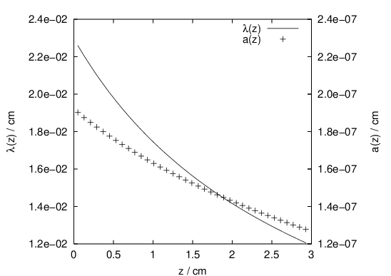
The particle density of channeling positron beams decreases exponentially along the channel Biruykov et al. 1996; Korol et al. 2001. The dechanneling length for positrons of GeV and is approximately 1.5 cm and the number of undulator periods on this length is about 75. The emitted undulator radiation should have high intensity and narrow spectral width. The energy of photons at the first harmonic emitted in the forward direction is MeV and the spectral width can be estimated as keV.
4 Growing of crystals with periodically bent channels
In this section we propose a method of preparing crystals with periodically bent channels whose shape function has either the pure sine form, , or a more general one defined by (2).
In Breese 1997 the deflection of proton beams by means of strained crystal layers was demonstrated. The construction of the crystals was described and experimental data that proves the deflection of protons was presented.
Using well-known methods of crystal growing (like molecular beam epitaxy or chemical vapor deposition, see the references in Breese 1997) it is possible to add single crystal layers onto a substrate. Let us consider a pure silicon substrate on which a layer is added ( denotes the germanium content in this layer). The doping with germanium leads to the enlargement of the lattice constant of the added layer. The strain due to the lattice mismatch of the substrate and the layer leads to an increase of the lattice spacing perpendicular to the surface of the substrate (the -direction in figure 7). The lattice constant parallel to the surface remains unchanged.
Prior to discussing the growing of periodically bent channels, let us summarize the main ideas presented in Breese 1997 that we need for our description. The spacing between the (100) layers is Å in Si and Å in Ge. The distance between two layers is given by , where . In Breese 1997 the critical thickness of the strained layer is discussed. If the thickness of the strained layer is larger than the critical value , then lattice defects appear and destruct the channels.
To obtain periodically bent channels, one starts with a pure silicon substrate and adds layers with continuously increasing Ge content. This results in bending of the (110) channels in the direction of the (100) channels. The periodicity of the shape requires the change of the direction of the bending toward the (010) channels. This, in turn, can be achieved by reducing until it reaches 0. Figure 7 schematically illustrates the first period of the bent (110) channel.

The last (within the first period) crystal layer consists of pure silicon, so that the second period can be built up on top of the first in the same manner. To be captured by the bent channel, the positron beam should be directed towards the (110) channel of the substrate.
The crystal strain is strongest after half a period, when the germanium content reaches its maximum. The thickness of the layers corresponding to half a period needs to be smaller than the critical thickness . If this condition is met, then crystals with arbitrary number of undulator periods can be constructed.
We now present the formulas that allow to calculate the germanium content as a function of the thickness of the crystal for a given shape .
The differential equation which relates the (local) curvature of the bent channel and the function reads:
| (9) |
where is the coordinate in the direction of the crystal growth, and . The prime denotes the derivative with respect to the argument.
To illustrate the application of equation (9) we consider two examples. First we discuss growing the Si crystal with the sine-like shape with cm and cm. These parameters correspond to the undulator emission spectrum presented in figure 2 for . The germanium content obtained by solving numerically the differential equation (9) is plotted in figure 8.

The maximum germanium content is 5%. The layer thickness that corresponds to half a period is given by cm. The critical thickness for a strained crystal with 5% of Ge is about cm Breese 1997.
The second example concerns the shape function given by (2) with and as in figure 6. To find the dependence in this case is not so straightforward as for the sine profile. Indeed, if one starts integrating (9) from , then the solution results in negative values of . To understand this non-physical result we take a closer look at (9). For small this equation acquires the following approximate form:
| (10) |
which leads to
| (11) |
Using the values - and -values shown in figure 6 one finds that the right hand side can be negative for some values .
To avoid this problem one can consider the crystal growth in the inverse direction: for . Then the factor decreases with increasing and the integral in (11) is positive for all .
The projectiles are injected not through the substrate, as in the first example, but from the opposite side of the crystal. The results of the calculation of the germanium content are shown in figure 9.

The maximal germanium content is smaller than 0.65% which gives a critical thickness of cm (see Breese 1997). Thus the critical thickness is much larger than the thickness of the layers: cm. Over the total length of the crystal (about 3 cm) the minimal Ge content grows continuously up to . The critical thickness for this Ge content is about 9 cm Breese 1997 which is three times larger than the length of the crystal.
5 Summary and outlook
In this work we have discussed the high-energy regime of the undulator radiation emitted by ultra-relativistic positrons channeling in periodically bent crystal channels.
This regime is typical for positron energies well above 10 GeV, when the channeling effect is accompanied by noticeable radiative losses. The latter, being mainly due to the channeling radiation, lead to the gradual decrease of the positron energy. This, in turn, strongly influences the stability of the parameters of the emission of undulator radiation.
We demonstrated that the frequency of the undulator radiation can be maintained constant provided the parameters of the periodic bending are changed with the penetration distance to take into account the decrease of the projectile energy.
Our investigation shows that the discussed modification of the shape of the crystal channels allows the generation of undulator radiation of high-energy photons (up to tens of MeV). The calculation of the spectral distributions of the emitted photons in this regime is currently in progress and will be reported soon.
We described a method that should allow the growing of the crystal channels that are necessary for the experimental measurement of the photon spectra. The feedback from experimentalists would be very helpful to check the models and assumptions that were used in this work.
References
- Korol et al. (1998) Korol, A. V., Solov’yov, A. V., and Greiner, W., J. Phys. G., 24, L45 (1998).
- Korol et al. (1999) Korol, A. V., Solov’yov, A. V., and Greiner, W., Int. J. Mod. Phys. E, 8, 49–100 (1999).
- Mikkelsen and Uggerhøj (2000) Mikkelsen, U., and Uggerhøj, E., Nucl. Inst. and Meth. B, 160, 435 (2000).
- Korol et al. (2000) Korol, A. V., Solov’yov, A. V., and Greiner, W., Int. J. Mod. Phys. E, 9, 77–105 (2000).
- Gemmel (1974) Gemmel, D. S., Rev. Mod. Phys., 46, 129 (1974).
- Biruykov et al. (1996) Biruykov, V. M., Chesnokov, Y. A., and Kotov, V. I., Crystal Channeling and its Application at High-Energy Accelerators, Springer, Berlin, 1996.
- Krause et al. (2000) Krause, W., Korol, A. V., Solov’yov, A. V., and Greiner, W., J. Phys. G: Nucl. and Part. Phys., 26, L87–L95 (2000).
- Baier et al. (1998) Baier, V. N., Katkov, V. M., and Strakhovenko, V. M., High Energy Electromagnetic Processes in Oriented Single Crystals, World Scientific, Singapore, 1998.
- Bak et al. (1985) Bak, J., Ellison, J. A., Marsh, B., Meyer, F. E., Pedersen, O., Petersen, J. B. B., Uggerhøj, E., and Østergaard, K., Nucl. Phys. B, 254, 491–527 (1985).
- Uggerhøj (1993) Uggerhøj, E., Radiation Effects and Defects in Solids, 25, 3–21 (1993).
- Korol et al. (2001) Korol, A. V., Solov’yov, A. V., and Greiner, W., J. Phys. G: Nucl. and Part. Phys., 27, 95–125 (2001).
- Abramowitz and Stegun (1984) Abramowitz, M., and Stegun, I. A., Pocketbook of Mathematical Tables, Dover Publications, New York, 1984.
- Breese (1997) Breese, M. B. H., 132, 540–547 (1997).