The influence of the dechanneling process on the photon emission by an ultra-relativistic positron channeling in a periodically bent crystal. published in J. Phys. G: Nucl. Part. Phys. 27 (2001) 95–125, Copyright 2001 IOP Publishing Ltd., http://www.iop.org
Abstract
We investigate, both analytically and numerically, the influence of the dechanneling process on the parameters of undulator radiation generated by ultra-relativistic positron channelling along a crystal plane, which is periodically bent. The bending might be due either to the propagation of a transverse acoustic wave through the crystal, or due to the static strain as it occurs in superlattices. In either case the periodically bent crystal serves as an undulator which allows to generate X-ray and -radiation.
We propose the scheme for accurate quantitative treatment of the radiation in presence of the dechanneling. The scheme includes (i) the analytic expression for spectral-angular distribution which contains, as a parameter, the dechanneling length, (ii) the simulation procedure of the dechanneling process of a positron in periodically bent crystals. Using these we calculate the dechanneling lengths of 5 GeV positrons channeling in Si, Ge and W crystals, and the spectral-angular and spectral distributions of the undulator over broad ranges of the photons. The calculations are performed for various parameters of the channel bending.
pacs
41.602
1 Introduction
In this paper we proceed with the investigation of the properties of the spectrum of emitted photons accompanying ultra-relativistic positron planar channeling through a crystal which is periodically bent, as it is illustrated in figure 1. This phenomenon was described recently in [1, 2] and was called Acoustically Induced Radiation (AIR). It was noted that the periodic pattern of crystal bendings (which can be achieved either through propagation of a transverse acoustic wave or by using static periodically strained crystalline structures [2, 3]) gives rise to a new mechanism of electromagnetic emission of the undulator type, in addition to a well-known ordinary channelling radiation [4, 5]. The mechanism of the AIR is as follows. Provided certain conditions are fulfilled [2] the beam of particles, which enters the crystal at a small incident angle with respect to the curved crystallographic plane, penetrates through the crystal following the bendings of its channel. This results in transverse oscillations of the beam particles (additional to the oscillations inside the channel due to the action of the interplanar force). These oscillations become an effective source of spontaneous radiation of undulator type due to the constructive interference of the photons emitted from similar parts of the trajectory. It was demonstrated [2] that the system “ultra-relativistic charged particle + periodically bent crystal” serves as a new type of undulator, and, consequently, as a new source of undulator radiation of high intensity, monochromaticity and of a particular pattern of the angular-frequency distribution.
The main subject of the present study is the detailed and accurate quantitative consideration of the influence of the dechanneling process [6] on the parameters of the AIR which are the intensity and the specific pattern of the spectral-angular and spectral distributions. The dechanneling, i.e. the decrease in the volume density of the channeled particles with penetration distance due to the multiple scattering of the projectiles with the target electrons and nuclei, is the parasitic effect which leads to the restriction on the crystal length and, correspondingly, on the number of the undulator periods , which, in turn, defines the intensity of the AIR radiation [2]. The factor, which plays a crucial role in obtaining the accurate data for the AIR characteristics, is a so-called dechanneling length , which is a mean penetration distance covered by a channeling particle. The quantity depends on the projectile energy, the type of the crystal and crystallographic plane, and on the parameters of the channel bending (these are explained in more detail below in this section). In this connection the following problems are solved and discussed below in the paper:
- (i)
We propose the scheme for accurate quantitative treatment of the AIR in presence of the dechanneling (section 3). As a result, we evaluate simple analytic expression for spectral-angular distribution of the AIR which contains, as a parameter, the dechanneling length.
- (ii)
We introduce the algorithm of the simulation procedure of the dechanneling process of a positron in periodically bent crystals (section 4).
- (iii)
Using (ii) we calculate the dechanneling lengths of 5 GeV positrons channeling in Si, Ge and W crystals the (110) plane of which are periodically bent (section 5). The calculations are performed for various parameters of the channel bending.
- (iv)
Using (i) and (iii) we calculate the spectral-angular and spectral distributions of the AIR over broad ranges of the photons emitted by 5 GeV positrons channeled in Si and W (section 6).

In our previous papers [2] (see also [7, 8]) we have estimated the role of the dechanneling by assuming simple relation to be valid. The magnitude of was estimated on the basis of the diffusion theory (see [9, 10, 11, 12]) with some corrections introduced due to the bending of the crystal [12, 13]. On the basis of these estimates we carried out the calculations of the AIR spectra for various energies of the projectile, different types of the crystals and crystallographic plane and for various parameters of the channel bending (these are explained in more detail below). It was also pointed out [2] that the system “ultra-relativistic charged particles + periodically bent crystal” leads, in addition to the spontaneous radiation, to the possibility of generating stimulated emission, similar to the one known for a free-electron laser [14] in which the periodicity of a trajectory of an ultra-relativistic projectile is achieved by applying a spatially periodic magnetic field. In connection with the stimulated AIR it was noted in [2] that to achieve a noticeable degree of amplification one has to operate with a positron bunch of a high volume density. The dechanneling length played a crucial role in these estimations by influencing the intensity of the spontaneous AIR as well as the gain factor and the corresponding value of the positron bunch volume density for the stimulated AIR. Indeed, increasing of the dechanneling length by a factor of 2 results in decreasing of the channeling beam density needed to achieve large gain almost by by a factor of 10 [2].
By utilizing the numeric scheme outlined in section 4 (to our knowledge it is the first time that the dechanneling process is simulated in a periodically bent crystal) we demonstrate further in section 5 that the simple estimation of made in [2] in many cases produces the results which are noticeably smaller then more accurate ones. This results, consequently, in essential (up to the order of magnitude for heavy crystals) difference in the intensities of the AIR radiation (section 6) computed by using the estimated, , and the calculated, , values of the dechanneling lengths.
Prior to presenting our main results let us formulate the important criteria which are used further in the paper.
The planar channeling of an ultra-relativistic projectile in a straight crystal (for reviews see [15, 16, 17]) occurs only if the entrance angle of the projectile velocity with respect to the mid-plane does not exceed the critical angle of channeling [6]
| (1) |
where the quantity (often called as the Lindhard angle) is defined as . Here is the interplanar potential-well depth, is the relativistic factor of the projectile and is its mass (below we consider only the channeling of positrons, if otherwise is not explicitly stated).
The criterion for a stable channeling of an ultra-relativistic particle in a bent crystal was formulated in [18] and has clear physical meaning: the maximum centrifugal force due to the channel bending must be less than that of the interplanar field. Provided this condition is fulfilled, the beam of channeling particles at each instant moves inside the channel, especially parallel to the bent crystal midplane as it does in the case of linear channeling. The dynamics of the particles channeled in crystals bent with a constant (or slowly varied) curvature is described in details in [12, 13, 19, 20, 21, 22] (see also the references therein). In the cited reviews the main accent was made on channeling of heavy projectiles due to the growing interest for using bent crystals for extraction, bending and splitting of high-energy beams (for the latest review see [22] and the references therein.
For a periodically bent crystal the criterion for a stable channeling can be written in the form [2]
| (2) |
where is the maximum value of the interplanar field, is the minimum curvature radius of the bent channel centerline. Introducing the shape function , which describes the profile of the centerline (see figure 1), the minimum curvature can be written in terms of the amplitude and the period of : . Thus, for a given crystal and its crystallographic plane, the condition 2 establishes the ranges of projectile energies and the parameters and inside which the channeling in a periodically bent channel can effectively occur.
The channeling radiation [4, 5] formed by ultra-relativistic positrons channeled in various straight crystals has been studied extensively both theoretically (e.g. [17, 16, 23, 24] and references therein) and experimentally [25, 26, 27, 28, 29].
Several papers [30, 31, 21] have treated the radiation emitted by light projectiles channeled in non-periodically one-arc bent crystals. In this case the channel bending gives rise to the synchrotron-type radiation in addition to the channeling one. In the cited papers it was demonstrated that for small values of the parameter (i.e. for large curvatures of the bending) the photon energies corresponding to the maximum intensity of the synchrotron radiation do not exceed the energy of the first harmonic of the channeling radiation.
When the shape of the bent channel becomes periodic the additional radiation becomes of the undulator type [32, 16, 24, 33] rather than the synchrotron one. Then, there appear two essentially different regimes which are defined by the magnitude of the ratio [2, 8]. In the case , which can be realized either by applying low-amplitude transverse ultrasonic wave [34, 35, 36, 37, 38] or by using a supperlattice crystalline structure [35], the characteristic frequencies of the two types of radiation can become compatible, and thus, one can consider, at least theoretically, the phenomenon of the resonant enhancement of the photon yield due to the coupling of these mechanisms. However, as it was demonstrated in [2, 7, 8], in the limit the intensity of AIR is noticeably small compared not only with that of the channeling radiation but also with the intensities of the radiative background mechanisms, such as coherent and incoherent bremsstrahlung. Hence, it is highly questionable whether the AIR can be considered as a new phenomenon in the limit of low values of .
On the contrary, if the amplitude of the shape function and the interplanar spacing satisfy strong inequality
| (3) |
then (i) the characteristic frequencies of the AIR and the channeling radiation are well-separated (this is the consequence of both conditions, (3) and ), (ii) the intensity of the AIR is essentially higher that that of the ordinary channeling radiation [2, 7, 8]. In this case the undulator-type radiation due to the periodic structure of the crystal bending can be considered as a new source of the emission within the - and -range.
Below in the paper we assume that both strong inequalities (2) and (3) are fulfilled. It is important to mention that in our scheme the amplitude is subject not only to the condition (3) but also is much smaller compared with the period of : . Hence, neither the interplanar spacing nor the distance between neighbouring lattice atoms are changed (in more detail it is discussed in section 4.1).
To conclude the introductory part we note that two realistic ways of “preparation” of a periodically bent channel may be discussed [1, 2]. It is feasible, by means of modern technology, to grow the crystal with its channels been statically bent according to a particular pattern. In particular, the crystalline undulator can be constructed based on graded composition strained layers in a superlattice [3] (see also [39, 40]). Another possibility is to use high-amplitude transverse ultrasonic wave. In the latter case the parameters of the undulator can be easily tuned by varying the amplitude and the frequency of the acoustic wave. It was demonstrated [2] that the acoustically-based undulator can be created by applying the supersonic waves within the frequency range MHz which is achievable in the experiments on propagating the positron beams through acoustically-excited crystals [41].
2 The AIR radiation in absence of the dechanneling
Let us consider the spectral-angular distribution of the photons emitted during the projectile positron planar channeling in a periodically bent crystal along the direction (see figure 1). The motion of the particle occurs in the -plane, so that its radius vector and the velocity are given by , where and are the unit vectors along the - and -directions, respectively.
Provided the conditions (1-3) are fulfilled the photon spectrum is formed due to the ordinary channeling mechanism and to the AIR, which prevail over two other radiative background mechanisms, coherent and incoherent bremsstrahlung. It has been established, both theoretically and experimentally (e.g. [16, 26, 28]), that the total radiative losses of a positron channeling in a straight crystal are essentially smaller than its energy provided GeV. This estimate is correct in the case of channeling through periodically bent crystal as well [7].
Therefore, restricting from above the range of by the value , one can assume that the emitted photon energies satisfy . This inequality allows to consider the process of the photon emission within the framework of classical electrodynamics (e.g. [42]).
The distribution of the energy radiated in the cone along the direction and within the frequency interval is given by the following expression
| (4) |
where , is the time of flight through the crystal of thickness , . The solid angle of the photon emission is characterized by two polar angles and . The functions and are given by
| (5) |
The short-hand notations used here are and .
Assuming that the relativistic factor of the projectile satisfies strong inequality , one can carry out the expansion of the functions and in powers of (see e.g. [16]). Then, retaining the senior non-vanishing terms, one transforms the r.h.s. of (4) to a form which is more suitable for analytical and numerical analysis:
| (6) |
where
| (7) |
The modified phase function reads as
| (8) | |||
| (9) | |||
| (10) |
The last relation defines the so-called undulator parameter , which is commonly used in the theory of the undulator radiation (e.g. [16]). This quantity is related to the mean-square velocity in the -direction, which is transverse with respect to the centerline of the bent channel (see figure 1).
If one neglects the processes of inelastic scattering by the crystal electrons and nuclei, then the motion of the positron in the channeling regime can be described within the framework of the continuum approximation [6, 15] for the interaction potential between the projectile and lattice atoms. Within this approximation and in the case of periodically bent channel the dependence , which enters the r.h.s. of (7-9) and, thus, defines the spectral-angular distribution (6), can be obtained as follows [7, 8].
At any given moment the -coordinate of the projectile can be presented as a sum of two terms
| (11) |
Here is the displacement due to the channel bending. The quantity stands for the displacement of the projectile from the centerline of the channel. The equation of motion for reads [43]
| (12) |
where the dot sign stands for the time derivative, is the derivative of the interplanar potential which depends on , and . The first term on the r.h.s. represents the acceleration of the particle due to the action of the interplanar force, while the second one is the acceleration due to the centrifugal force. Note that on the r.h.s. one may put after carrying out the differentiation , because all the deviations from of the particle’s velocity along the -axis were taken into account when writing eqs. (7-9).
Solving the equation of motion (12) and, then, using the result, combined with (11), in (7-9), one obtains the total spectral-angular distribution of the radiation (6). This scheme was used in our recent papers [8] where the results of the numerical calculations of the spectra were presented for various shapes and with using different approximations for the interplanar potential .
A particle which channels through periodically bent crystal experiences two types of oscillations in the transverse direction, as it is seen from (11). Firstly, there are the channeling oscillations due to the action of the interplanar potential. The oscillations of the second type (henceforth we refer to them as to the “undulator oscillations”) are related to the periodicity in the shape of the centerline of the channel inside which the particle moves. The characteristic frequencies of these oscillations, denoted as and respectively, can be estimated as follows
| (13) |
Correspondingly, the quantities define the characteristic frequencies, and , of the photons emitted due to the channeling and the undulator oscillations:
| (14) |
Taking into account the relations (2) and (3) one estimates the relative magnitude of and :
| (15) |
Hence, the characteristic frequencies of the AIR and the ordinary channelling radiation are well separated [7], and, what is also very important, in the region there is no coupling of the two mechanisms of the radiation [8].
The results of numerical calculation of the spectral distribution (6) presented in [8] clearly suggest that the characteristics of the AIR spectra (the position of the peaks of the radiation, their width, the radiated intensity) are, practically, insensitive to the choice of the approximation used to describe the interplanar potential . Moreover, if being interested in the spectral-angular distribution only in the region , then one may disregard the channeling oscillations and to assume that the projectile moves along the centerline of the bent channel. In this case, taking into account the periodicity of the undulator motion, the r.h.s. of (6) can be presented in the form which clearly exhibits all the characteristic features of the AIR radiation.
Let assume that there is integer number of the undulator periods on the crystal length, . Also, for the sake of transparency of the analytic expressions, let consider the shape function of the form
| (16) |
Let assume that there is integer number of the undulator periods on the crystal length, . Then, the spectral-angular distribution of the AIR radiation can be represented in the form [2, 24]
| (17) |
Here the subscript in the notation indicate the number of undulator periods, is the so-called undulator frequency, and the quantities () stand for the integrals
| (18) | |||
| (19) |
The information on the specific pattern of the undulator radiation, namely on the positions of the narrow maxima in the spectral-angular distribution (17), is accumulated in the factor which equals to
| (20) |
This function, which is well-known in the theory of undulator radiation (see e.g. [16, 24]) and in classical diffraction theory [42], defines the profile of the line of the emission in an ideal undulator. It has sharp maxima at the points where . The integer values define (see the first equation in (19)) the characteristic frequencies (harmonics) of the undulator radiation for which the spectral-angular distribution (17) reaches its maxima:
| (21) |
The natural width of each line of the emission can be estimated as and is independent on the harmonic number .
The largest number of the radiated harmonics, , can be estimated as (see e.g. [16, 24]), so that in the range the spectral-angular distribution of the AIR represents by itself the set of narrow well-separated peaks. The radiation intensity at is proportional to the square of the total number of the undulator periods, , reflecting the coherence effect of radiation.
It follows from (21) that the position of the peaks are dependent on the relativistic factor, on the emission angle , and on the undulator parameter .
The only feature, related to the channeling oscillations, which modifies the formulae (17-21), which describe the AIR spectrum, concerns the definition of the undulator parameter (see (10)).
When the channeling oscillations are disregarded completely (this means omitting the term on the r.h.s. of (11)) then the undulator parameter equals , and for given is defined only by the amplitude and the period of the shape function .
To account for the channeling oscillations and to modify the definition of one can use the following arguments. The quantity is proportional to the the mean-square velocity . The latter, according to (11), can be written as follows:
The last term on the r.h.s. contains the product of the factors oscillating with incompatible frequencies (see (15), and, therefore, it disappears when one carries out the averaging over the time interval . Hence, the square of the undulator parameter can be written as follows
| (22) |
The results presented in [8] demonstrate that in the region the spectral-angular distribution, obtained by means of the exact procedure which includes (i) numerical integration of the equation of motion (12) with the interplanar potential considered within the the Molière approximation, (ii) subsequent evaluation of the integrals in (6), and (iii) by further averaging of the result over all channeling trajectories, can be accurately reproduced by using (19) and (22) with the term calculated within the harmonic approximation for . The use of (19) instead of (6) simplifies the numerical procedures considerably, leading to the reduction, by orders of magnitude, of the CPU time.
3 The AIR radiation in presence of the dechanneling
If the dechanneling is neglected, one may unrestrictedly increase the intensity of the AIR by considering larger -values. In reality, random scattering of the channeling positron by the electrons and nuclei of the crystal leads to a gradual increase of the particle energy associated with the transverse oscillations in the channel. As a result, the transverse energy at some distance from the entrance point exceeds the depth of the interplanar potential well, and the particle leaves the channel. Consequently, the volume density of the channeled particles decreases with the penetration distance . Although the exact explicit dependence of the channeled fraction of the particles on ( is the volume density of the channeled particles at the entrance) hardly can be obtained by analytical means due to the complexity of the accurate treatment of the multiple scattering problem in medium, it has been argued [12, 17] that far from the entrance point can be described by the exponential decay law
| (23) |
Basing on this relation, below in this section we present a model which allows to modify the spectral-angular distribution (17) by taking into account the influence of the dechanneling effect.
Let us assume that the period of the shape function and the dechanneling length satisfy the strong inequality . If so, then the number of particles (per unit volume) , which dechannel within the interval , is small compared with the number of the particles which reach the point . The inequality allows also to introduce the (discrete) probability of the event, that after channeling through periods of the undulator () the particle dechannels within the subsequent -th period. In accordance with (23) the probability is written as follows
| (24) |
and is subject to the normalization condition . In (24) we introduced the quantity which is the number of the undulator periods within the dechanneling length. Since , then the deviation of from the nearest integer is of no importance, and henceforce the quantity is treated as the integer much larger than one.
With the help of (24) one can construct the following quantity, which characterizes the spectral-angular distribution of the AIR radiation formed in the crystal of the length (and of the corresponding number of the undulator periods ) and which accounts for the dechanneling effect:
| (25) | |||||
| (26) |
with
| (27) |
Let us note here the difference between the averaging procedure suggested above by relation (25) and the conventional scheme (see e.g. [16]) for obtaining the characteristics of the electromagnetic radiation accompanying the motion of an ultra-relativistic particle in medium. The latter approach prescribes that, in the presence of multiple scattering, the radiative spectrum (4) formed during the motion of a projectile in an external field along some particular trajectory must be averaged over all allowed trajectories. This operation is carried out with the help of the distribution function satisfying the corresponding kinetic equation [16]. Although the AIR radiation in medium is not an exclusion from this rule, in this case there is one peculiarity which justifies the use of the averaging procedure (25). As mentioned above, the motion of a positron channelled through a periodically bent crystal is characterized by two essentially different modes. The “fast” mode corresponds to the channeling oscillations inside the channel, the “slow” mode describes the motion of the particle along the channel centerline. The AIR is due to the “slow” mode and in the case its characteristics are almost independent on the parameters of the fast channeling oscillations [2, 8]. Hence, if one is interested in the spectral-angular distribution of the AIR only, then it is sufficient to totally disregard the channeling oscillations and to assume that the particle moves along the fixed trajectory which is defined by the profile of the bent channel centerline. The intensity of the AIR radiation is then defined by the number of the -periods which the particle passes before leaving the channel due to the multiple scattering. The value of is subject to the probability distribution (24) which, in turn, is based on the exponential decay law (23).
Hence, to obtain the parameters of the AIR radiation in presence of the dechanneling it is sufficient to substitute the factor (see (20)) with its averaged value defined in (27). The sum on the r.h.s. of (27) is carried out straightforwardly resulting in the following expression for :
| (28) | |||
Although more cumbersome, if compared with simple formula (20), the structure of r.h.s. of (28) can be readily analyzed.
As well as the factor , the function has sharp maxima at the points which correspond to the frequencies defined as in (21). For given the maximum value , which is the same for all , is equal to
| (29) |
and monotonously increases with the number of the undulator periods.
The limit corresponds to a thin crystal, . In this case the number of the channeling particles does not change noticeably on the scale , so that the AIR intensity is proportional to as in an ideal undulator. For the probability of the particle to channel through the whole crystal length decreases, and the value of starts to deviate from the -law. In the limit of very thick crystal, , reaches its maximum value .
The r.h.s. of (28) reduces to simple expressions in two limiting cases of thin and infinitely thick crystals:
| (30) |
Both limiting expressions have clear physical meaning. For () the dechanneling is of no importance, and, therefore, the structure of the characteristic line of the AIR is that of an ideal undulator, eq. (20). With () increasing the profile of the characteristic line changes and, finally, becomes of the Lorenz-type in the limit and for . The qualitative explanation of this result can be given if one interprets the relation (23) in terms of quantum mechanics. Then, the r.h.s. is proportional to the squared modulus of the projectile wave-function which corresponds to the bound (channeled) state characterized by a complex energy. Indeed, the wave function of the channeled particle can be presented in the form (e.g. [24]) , where corresponds to the unbound longitudinal motion of the particle, and describes the transverse motion in the channel. Provided the multiple scattering is excluded the function corresponds to a stationary bound state of the transverse motion ( is the energy associated with the transverse degree of freedom). In this case, the normalization condition means, that the probability to find the particle inside the channel does not depend on time , which, in turn, is related to the penetration distance through . Random scattering by the electrons and nuclei can be incorporated in this picture by adding the imaginary term to the energy of the transverse motion, , where is the total width associated with the transitions to the unbound (dechanneled) continuum due to the multiple scattering. Hence, the normalization condition acquires the form . Comparing this expression with (23) one finds which is exactly the quantity which defines the shape of the resonant line of in the case (the second relation in (30)).
The change in the shape of the characteristic line is illustrated in figure 2 where the function is plotted for several values of (as indicated) in the vicinity of the point . For the sake of comparison we plotted also the dependence for (the thin solid line) which characterises the line shape in an ideal undulator without the decrease in the volume density of the channeled particles.

Hence, the expression (26) combined with (28) describes the spectral-angular of the total radiation in the range formed during a passage of an ultra-relativistic positron along periodically bent crystallographic plane. All the complexity of the trajectory related to the channeling oscillations are incorporated in the undulator parameter (see (22)). The effect of the dechanneling is included in the factor , eq. (28), which depends on two parameters, and . The number of the undulator periods can be varied by changing the length of the crystal or/and by changing the period of the shape function (see figure 1)).
In the case of a straight channel the dechanneling length depends on the type of a crystal and on the energy of projectile [15, 17]. For a crystal bent with constant curvature the quantity becomes also dependent on . The methods for estimating for heavy projectiles channeling in crystals bent with are discussed in [12]. To our knowledge, no detailed study has been carried out of the dependence of the dechanneling length on the parameters of the shape function in the case of a light projectile (a positron) channeling through periodically bent crystal. In the next two sections we present the approach and the results of numerical calculation of in this case.
4 Simulation of the dechanneling process in periodically bent crystals
As it was demonstrated above the intensity of the radiation and the profile of the line of the AIR are defined, to a great extent, by the parameter .
This section is devoted to the description of the model which we used to calculate the dechanneling length for an ultra-relativistic positron channeling through periodically bent crystal. Our approach is based on the simulation of the trajectories and the dechanneling process of an ultra-relativistic positron. This is done by solving the three-dimensional equations of motion which account for (i) the interplanar potential, (ii) the centrifugal potential due to the crystal bending, (iii) the radiative damping force, (iv) the stochastic force due to the random scattering of projectile by lattice electrons and nuclei.
We analyze the dependence of on the energy of the projectile, the type of the crystal and crystallographic plane, the parameters of the shape function . The latter include two factors: the parameter and the ratio (see eqs. (2-3)).
The results of our calculations of the quantity , presented in section 5, are used further in section 6 to calculate the spectral-angular and the spectral distributions of the AIR.
4.1 Equations of motion in periodically bent crystal with account for the radiation damping
Below we outline the derivation of the equations of motion for an ultra-relativistic positron channeled in a periodically bent crystal. Contrary to the case of a heavy projectile, a light projectile (a positron, an electron) with looses its energy, when passing through matter, mainly due to the radiative losses (e.g. [44]). In this inequality is the atomic number of the crystal atoms. Hence, the radiative losses exceed the losses due to the ionizing collisions starting with MeV in Si, and MeV in W. Therefore, accurate treatment of the equations of motion of the channeled ultra-relativistic positron must account for the effect of the radiation damping [45, 46, 47]. In our scheme by introducing the classical radiative damping force [42].
The equations of motion for a relativistic particle of mass and charge moving in an external static electric field read as follows [42]:
Here
| (34) |
is the radiative damping force due to the presence of the electric field . The latter is related to the interplanar potential through , where is the radius vector.
Let the crystal centerline be bent as it is presented in figure 1. We impose the following condition on the derivative of the periodic profile function :
| (35) |
Then, the length of the bent crystal, the interplanar spacing , and the local curvature of the centerline satisfy the relations
| (36) |
Here the subscript refers to the straight channel. When combined, the relations (36) lead to the conclusion that the parameters of the bent channel, which are the channel width and the distance between the atoms of any crystallographic plane, are equal to the their values in the case of straight crystal provided one neglects the terms of the order and higher. This, in turn, allows to formulate the following two conditions regarding to the interplanar potential in periodically bent crystal:
- 1.
within any single bent channel the potential depends only on the variable which is the distance from the point to the channel centerline (see figure 3);
- 2.
the dependence of on in the bent channel is identical to that in the linear one. Therefore,
(37)

Eq. (37) leads to the following definition of the interplanar static electric field :
| (38) |
Using (38) in (34) and in (4.1) and carrying out some algebra one ends up with the following system of coupled equations
| (39) | |||||
| (40) | |||||
| (41) |
Here cm is the classical electron radius.
Since then dependence is uniquely defined provided the functions , and are known.
4.2 Equations of motion with account for the random collisions with target electrons and nuclei
Random scattering of a projectile by target electrons and nuclei leads to deviation of the trajectory from that which is obtained by solving equations of motion (39-41). There are two different approaches aimed to account for these deviations. The first approach is based on the diffusion theory applied to describe the multiple scattering (e.g. [11, 17, 48, 49]. The second approach is in direct computer simulation of the scattering process [50, 12]. In the present paper we adopt the scheme similar to the one described by Biryukov [50, 12].
Scattering from target electrons results in two changes in the projectile motion. The first one is the gradual decrease in the projectile energy due to the ionization losses. The second effect of the collisions is that they lead to a chaotic (random) change in the direction of the projectile motion.
The scattering from target nuclei results in a chaotic (random) change in the direction of the projectile motion.
4.2.1 Ionization losses for a channeling positron
Although for an ultra-relativistic positron () passing through media the ionization losses are much smaller as compared with the radiative ones (see e.g. [51, 52]) they are incorporated into the scheme which is described here. The mean energy loss per path due to the electronic scattering can be written as a function of the distance from the midplane [12, 51, 52, 53]
| (42) |
The notations used here are as follows:
- •
cm2.
- •
The quantity is the mean concentration of electrons in the corresponding amorphous media. It is related to the mass density of the material, the atomic weight of the crystal and the atomic number of its atoms through (with mol-1 being the Avogadro number).
- •
is the local concentration of the electrons inside the channel. To calculate we use the Molière approximation.
- •
- •
The quantity is the maximum magnitude of the energy transfer from a projectile to a target electron. For an ultra-relativistic positron .
- •
The term is the correction due to the periodicity of the crystalline structure. The exact form of this correction was found in [55].
4.2.2 Random change in the direction of motion due to ionizing collisions
To account for the random change in the direction of motion due to single collisions with target electrons we followed the procedure proposed by Biryukov [50] for heavy projectiles but modifying his formalism for the case of a light projectile. For an ultra-relativistic positron travelling through a crystal the differential probability (per path ) of the relative energy transfer due to the the ionizing collisions with the quasi-free electrons is defined by the following expression [53, 56]:
| (45) |
The relative energy transfer defines a round scattering angle , measured with respect to the instant velocity of the projectile, through (see e.g. [42]) \numparts
| (46) | |||
| (47) | |||
| (48) |
Here eV characterises the average ionization potential of the crystal atoms. The maximum relative energy transfer results in , whereas leads to nearly forward scattering.
Following Biryukov [50] we used the distribution (45) to generate (randomly) the magnitude of when integrating the system of equations (39-40) and (44). The magnitude of the second (the azimuthal) scattering angle is not restricted by any kinematic relations, and is obtained by random shooting (with a uniform distribution) into the interval .
The algorithm of random generation of the -values is as follows. The two-fold probability satisfies the normalization condition
| (49) |
where is the interval inside which the probability of the projectile to undergo the ionizing collision accompanied by arbitrary energy transfer is equal to 1. The parameter (defined from (49)) is expressed through , and the local electron density as follows
| (50) |
Using these notations eq. (45) can be written as
| (51) |
Here the factor defines the probability of the collision (any) to happen on the scale , whereas the factor represents the normalized probability of the energy transfer between and . To generate random deviate with the probability distribution we used the algorithm described in [57].
The scheme outlined above implies that the ionizing collisions are treated as events. Hence, for each step of integration of the the system (39-40, 44) we first simulate the probability of the event to happen by generating a uniform random deviate and comparing it with . If then the scattering angles and are calculated and used to modify the direction of motion of the projectile but leaving the magnitude of the projectile velocity unchanged.
4.3 Random change in the direction of motion due to scattering from nuclei
The change in the projectile direction of motion due to the collisions with crystal nuclei was taken into account at every step when integrating the system (39-40), (44). The square of small deflection angle per path , was computed from a Gaussian distribution
| (52) |
Here is the mean-square deflection angle due to the scattering from nuclei in crystals. In the approximation suggested by Kitagawa and Ohtsuki [58]
| (53) |
where is the mean concentration of nuclei in an amorphous media, is the local concentration of the nuclei inside the channel. With the thermal vibrations taken into account the quantity , corresponding to the distribution of the nuclei of two neighbouring planes versus the distance from the midplane, is given by
| (54) |
with standing for the crystal temperature and denoting the thermal vibration root-mean-square amplitude.
5 Numerical results of the dechanneling process simulations
We used the scheme outlined in sections 4.1 and 4.2 for computer modelling of the dechanneling process of ultra-relativistic positrons in periodically bent crystals. The goal of these calculations was to obtain realistic dependences of the number of channeled particles versus the penetration distance . The interplanar potential was considered within the the Molière approximation at the temperature K.
The calculations were performed for 5 GeV positrons channelling along the crystallographic planes in Si, Ge, and W crystals. The shape function was chosen in the form (16). In this case the minimum curvature radius of the centerline bending equals , and, consequently, the parameter defined in (2) reads as . Thus, for given crystal and crystallographic plane, and for given the parameter and the ratio uniquely define the period .
In our calculations was varied from 0 to 0.5, and the considered ratios are: 0 (the case of a straight channel), 5,10, 15 and 20.
For each pair of the parameters and we simulated 2000 trajectories by solving the coupled system (39-40) and (44), which was integrated with the account for the random scattering from target electrons and nuclei as explained in section 4.2. The initial conditions were chosen as follows. The coordinates and were set to zero at the entrance, the transverse coordinate was obtained by random shooting (with a uniform distribution) into the interval . The vector of initial velocity was aligned with the tangent to the centerline at the entrance but with allowance for the spread in the incident angles . Hence, the initial values of the velocities and were obtained by random shooting (with a uniform distribution) into the interval . For each crystal the parameter was chosen as . The values for the Lindhard angle for 5 GeV positron channeling along (110) planes in Si, Ge and W are equal to , rad, respectively. Thus, the considered spread in the incident angles is about rad which is achievable in modern high-energy colliders (see e.g. [56]).
The first three figures represent the dependences of (normalized to the entrance value ) versus the penetration distance for Si, Ge and W crystals. The ratio equals 10. The curves in the figures refer to different values of as indicated. The value stands for the case of a straight channel. The corresponding values of the spatial period of the shape function can be calculated as and are presented in the table.


Let us discuss these results. First to be mentioned is that in all cases the dependences are monotonously decreasing functions which are smooth for all except for the steep change in the magnitude in the region close to . This change, , is the smallest for the straight channels and its magnitude increases with . Such a behaviour is explained as follows. The probability for the projectile to undergo the large-angle scattering from the crystal electrons or/and nuclei is proportional to the volume densities and (see (50-54)). The large-angle scattering, i.e. when , results in the increase of the kinetic transverse energy, which becomes high enough for the projectile positron to leave the potential well. Hence, all those particles which at the entrance move in the region of high nuclear and electron densities leave the channeling mode almost immediately. The volume density of crystal electrons is comparatively small in the inner region of the channel and sharply increases as (here is the Thomas-Fermi radius of the crystal atoms, is the Bohr radius), the density of target nuclei becomes noticeable for ( standing for the thermal vibration root-mean-square amplitude). This is illustrated by figure 7. Since in our simulations we assumed that the particles are uniformly distributed in the coordinate at the entrance point, then the fraction leaves the channel close to . This the mechanism of dechanneling in the vicinity of the entrance point [12] is intrinsic for both straight () and bent () channels. In addition to it, in the case of bent channel there is a process which is called bending dechanneling [12], and which is due to the change in the depth of the potential well. Indeed, inside the bent channel the transverse motion of the particle is subject to the action of the effective potential (see (39))
| (57) |
where and is the (local) curvature radius of the channel. For a channel bent as described by (16) . The particle could be trapped into the channelling mode provided its total energy associated with the transverse motion is less the minimal value, , of the two maxima points of the asymmetric potential well described by (57) [7, 12]. The potential reaches the magnitude of at some point which satisfies the condition and the absolute value of decreases with the growth of . Hence, the more the channel is bent, the lower the allowed values of the channelling oscillations amplitude are, and, consequently, the narrower is the interval of the initial values for which the trajectory from the very beginning will correspond to the channeling one.

Another feature to be mentioned in connection with the curves in figures 4-6 is the noticeable decrease, with the growth of , of the penetration distance which the projectile can achieve. If one assumes that the dependence satisfies the exponential-decay law (see (23)), then the curves demonstrate that the dechanneling length is the decreasing function of . This effect has been discuss in literature ([12, 13]) in connection with the heavy particles dechanneling in crystals bent with constant curvature. Physically clear quantitative arguments [12], based on the relationship between the diffusion coefficient and the mean-square angle of multiple scattering lead to the following estimate for the dechanneling length [12, 2] in the channel bent with the mean curvature
| (58) |
here the quantity is the critical (minimal) radius consistent with the channelling condition in a bent crystal (2). The quantity , with eV standing for the Thomas-Fermi ionization potential of the crystal atoms, is the Coulomb logarithm characterizing the ionization losses of an ultra-relativistic positron in amorphous media with account for the density effect (see e.g. [52, 54]).
The quantity is the estimated value of the dechanneling length for a straight channel. The factor is the correction due to the decrease of the potential well of (see (57)) in bent crystal.
In periodically bent crystal the mean curvature radius is proportional to (in particular, for the shape (16), ), hence the ratio . This estimate was used in [2, 7, 8] to calculate the characteristics of the spontaneous and stimulated emissions based on the AIR effect.
Basing on the estimate (58) one deduces that the dechanneling length is mainly determined by the value of the parameter and is not influenced by the ratio. This conclusion is supported by the results of our calculations. In figure (8) the dependences , obtained for different and values, are compared. It is seen that the variations between the curves with different but the same is much smaller than for the curves with the same ratio but different values.

The results of our calculations of the dechanneling lengths for GeV positrons in Si, Ge and W crystals obtained at different values of the parameter but for fixed ratio are presented in table 1. They are notated through (the quantities are the number of the undulator periods on the scale of ). The presented values of were obtained by fitting the smooth part of the curves (i.e. for the distances beyond the region of the steep decrease) with the exponent .
| \brCrystal: | Si, | Å, | cm | |||||
| cm | m | cm | cm | MeV | ||||
| 0.00 | - | 0.312 | 0.463 | - | - | - | - | |
| 0.05 | 15.697 | 100.9 | 0.281 | 0.430 | 25 | 39 | 1.38 | 1.08 |
| 0.10 | 7.849 | 77.1 | 0.253 | 0.393 | 32 | 51 | 1.42 | 1.53 |
| 0.15 | 5.232 | 63.0 | 0.225 | 0.321 | 35 | 51 | 1.37 | 1.87 |
| 0.20 | 3.924 | 54.5 | 0.200 | 0.223 | 36 | 41 | 1.31 | 2.16 |
| 0.25 | 3.140 | 48.8 | 0.175 | 0.170 | 35 | 35 | 1.24 | 2.42 |
| 0.30 | 2.616 | 44.5 | 0.153 | 0.102 | 34 | 23 | 1.18 | 2.65 |
| 0.35 | 2.243 | 41.2 | 0.132 | 0.078 | 31 | 19 | 1.13 | 2.86 |
| 0.40 | 1.962 | 38.6 | 0.112 | 0.042 | 29 | 11 | 1.09 | 3.06 |
| \brCrystal: | Ge, | Å, | cm | |||||
| cm | m | cm | cm | MeV | ||||
| 0.00 | - | 0.263 | 0.513 | - | - | - | - | |
| 0.05 | 8.465 | 81.8 | 0.237 | 0.450 | 29 | 55 | 1.37 | 1.50 |
| 0.10 | 4.232 | 57.8 | 0.213 | 0.364 | 36 | 63 | 1.26 | 2.13 |
| 0.15 | 2.822 | 47.2 | 0.190 | 0.269 | 40 | 57 | 1.15 | 2.61 |
| 0.20 | 2.116 | 40.9 | 0.168 | 0.176 | 41 | 43 | 1.05 | 3.01 |
| 0.25 | 1.693 | 36.6 | 0.148 | 0.095 | 40 | 26 | 0.98 | 3.36 |
| 0.30 | 1.411 | 33.4 | 0.129 | 0.060 | 38 | 18 | 0.92 | 3.68 |
| 0.35 | 1.209 | 30.9 | 0.111 | 0.028 | 35 | 9 | 0.86 | 3.98 |
| 0.40 | 1.058 | 28.9 | 0.095 | 0.012 | 32 | 4 | 0.82 | 4.25 |
| \brCrystal: | W, | Å, | cm | |||||
| cm | m | cm | cm | MeV | ||||
| 0.00 | - | 0.263 | 0.786 | - | - | - | - | |
| 0.05 | 2.018 | 42.2 | 0.215 | 0.637 | 50 | 151 | 0.89 | 3.26 |
| 0.10 | 1.009 | 29.9 | 0.193 | 0.453 | 64 | 152 | 0.69 | 4.61 |
| 0.15 | 0.673 | 24.4 | 0.172 | 0.226 | 70 | 93 | 0.58 | 5.64 |
| 0.20 | 0.505 | 21.1 | 0.153 | 0.027 | 72 | 13 | 0.51 | 6.52 |
| 0.25 | 0.404 | 18.9 | 0.134 | 0.007 | 71 | 4 | 0.46 | 7.29 |
| \br |
For each we included also the corresponding values of the undulator period , the minimum curvature radius , the energy of the first harmonics of AIR, , obtained from (21) for the forward emission (), and the values of the undulator parameter .
The quantities represent the the dechanneling length estimated from (58), is the corresponding number of the undulator periods on the scale of .
Comparing the calculated values with those estimated from (58) one notices that the latter underestimates the dechanneling length in the case of small values of the parameter : for Si, for Ge, and for W. It happens mainly due to the fact that the quantity , which enters (58), was obtained by using the Lindhard approximation for the interplanar potential . The latter overestimates the electron density inside the channel as compared with the Molière approximation used in the present calculations. Thus, the average multiple scattering angle is higher if calculated within the Lindhard approximation, and, consequently, the dechanneling lengths are lower. With increasing the ratio becomes less than one. This is explained as follows. When the parameter , and, consequently, the curvature of the channel bending, increases, then the minimum of the effective potential (57) is shifted from the midplane towards the atomic plane. Hence, the channeled particle moves in the region of higher electron density and, therefore, the probability of the large-angle scattering increases [12, 13]. This is mechanism of the dechanneling, which is additional to the bending dechanneling discussed above, is not accounted for by the estimate (58). Comparing the values for various it is seen that for large the dechanneling length rapidly goes to zero, and the main reason for this behaviour is the increase of the role of the large-angle scattering.
Another important feature to be mentioned is that the estimate (58) predicts the decrease in the dechanneling length for heavier crystals, whereas the more accurate calculations within the framework of the Molière approximation demonstrate that for the largest dechanneling lengths are in W, followed by the germanium crystal, and finally, the lowest values of are in the case of channeling in Si. With increasing the situations is reversed. To explain this behaviour let us compare the cases of Si and W crystals. The maximum values of the interplanar potential at temperature K are equal to eV for Si, and to eV for W. Thus, the critical transverse energy of the channeled positrons is approximately 6 times higher in W. Hence, were the mean electron densities in these crystal equal then the dechanneling length in W would be 6 times higher as compared to the silicon case. The ratio of the mean electron densities for the inner regions of the channels in W and Si is approximately . Therefore, the realistic estimate for the ratio is which is very close to that which can be obtained from table 1 for low -values. Our results for the relative magnitudes of for a positron channeling in Si and W coincides with the conclusion of made in [59] where the calculations of the dechanneling lengths were carried out for heavy particles in the case of moderate bending of the crystals.
As increases, and the trajectory of the particle shifts towards the atomic plane, the electron density in the region of the projectile motion increases as well. This increase is more pronounced for W (see figure (7)) leading to the relation in the range .
The important conclusion which can be made on the basis of the results presented in this section is the following. To achieve higher yield of the monochromatic radiation by means of the crystalline undulator it is necessary to use heavier crystals and to restrict the parameter by the range . Indeed, for these values the number of the undulator periods (this is valid for all crystals presented in the table), but the intensity of the AIR, which is mainly defined by the factor (see (26) and (30)), will be almost by the order of magnitude lager in the case of W than for Si and/or Ge crystals.
6 Results of calculations of the spectral-angular and spectral distributions of the AIR
The simulation of the dechanneling process, described in the preceding section, allows to establish the ranges of the parameter which to a great extent defines the characteristics of the AIR radiation in the presence of the dechanneling. In this section we present the results of calculations of the spectral-angular (see eq. (26)) and the spectral distributions of the AIR.
The general features of the angular distribution of the radiation formed in an acoustically based undulator were discussed in [2] where the effect of the dechanneling was taken into account by restricting the length of the crystal (and, hence, the number of the undulator periods) by the value , which, as it was demonstrated above, in many cases underestimates the dechanneling length, and, consequently, leads to the underestimation of the photon yield.
Figures 9(a)–9(d) present the spectral distribution (26) of the radiation emitted along the undulator axis, , for 5 GeV positron channeling along (110) planes in Si and W crystals. The spectra were calculated by using the parameters and as indicated in table 1 in the lines for Si, and for W. The number of the undulator periods varied from , as in figures 9(a,c) and the solid curves in figures 9(b,d), to (the long-dashed lines in figures 9(b,d)). For fixed different values of can be achieved by changing the length of the crystal. The sinusoidal profile of the channel bending can be created by applying the transverse acoustic wave. The velocities of the transverse supersonic waves propagating along (110) directions are equal cm/s for Si [60] and cm/s for W crystal [61]. Thus, the corresponding frequencies of the acoustic wave needed to to obtain m in Si and m in W (see the table) are: MHz, MHz.

The upper figures illustrate the structure of the spectral distribution in wide ranges of the emitted photon energy. Each peak corresponds to the emission into the odd harmonics [24, 16], the energies of which follow from (21) if putting . It is seen that all harmonics are well separated: the distance between two neighbouring peaks is MeV for Si and MeV in the case of W, whilst the width of each peak , estimated from (30) (the case ), is keV for Si and keV for W. The intensity of the first-harmonic peak in W is approximately 4.5 times larger than in the case of silicon crystal. This ratio is in agreement with the expression (26). Indeed, the intensity of the first-harmonic peak is proportional to the factor , which, in turn, is proportional to (see eqs. (21) and (30)). Using the data presented in the table one obtains that the ratio of these factors calculated for W and Si is .
The difference in the magnitudes of the undulator parameters, for Si and for W, explains number of the harmonics visible in the spectra [24, 16].
Figures 9(b,d) exhibit, in more detail, the structure of the first-harmonic peaks. For the sake of comparison we plotted the curves corresponding to different values of the undulator periods. It is seen that for the intensity of the peaks is no longer proportional to , as it is in the case of the ideal undulator without the dechanneling of the particles (Section 2). For both Si and W crystals, the intensities of the radiation calculated at exceeds those at (the thick solid curves in the figures) only by several per cent. Thus, the solid lines correspond to almost saturated intensities which are the maximal ones for the used crystals, projectile energies and the parameters of the crystalline undulator. It is worth noting that these intensities, obtained with realistic values of the dechanneling lengths , are noticeably higher than the ones corresponding to (the thin solid lines in the figures). The latter were used in [2] for the estimations of the yield of the AIR, both spontaneous and stimulated. It it seen from the figure that our earlier estimations were adequate for light crystals (the maximum of the thick solid curve exceeds that of the thin one by a factor of 3.5) but they essentially underestimated the yield of the AIR in heavy crystals, where the ratio of the intensities is almost 10.
In figures 10 and 11 we present the results of the spectral distribution of the radiation obtained by integration of the r.h.s. of (26) over the emission angle . The calculations were performed for 5 GeV positrons channeled in Si and W with the bending parameters as those mentioned above.


It is known from general theory of the undulator radiation by an ultra-relativistic projectile [24, 16] that it is emitted into the narrow cone along the undulator axis. The opening angle of this cone, depends on the two parameters, namely, on the relativistic factor and on the undulator parameter . For (the so-called dipole case) the radiation is concentrated within the cone with the opening angle . In the opposite limit, (the non-dipole case) the opening angle becomes larger, . Uniting both limiting cases one can state that for given and the maximum angle of the emission can be estimated as . In the case of a planar undulator, which is considered here, and for the cone is asymmetric with respect to the azimuthal () angle of the photon emission [2]. The opening angle is the largest for the emission within the undulator plane () and reaches its minimum value for the emission into the perpendicular plane ().
The five graphs in each of the figures reproduce the dependence of the quantity
| (59) |
on for different values of the parameter as it is indicated in the figures.
The parameter , defined above, equals to rad for Si and rad for W crystals.
The graphs (a)-(e) in each figure illustrate how the pattern of the spectral distribution changes with enlarging the opening cone . For small , when only the radiation emitted in the nearly forward direction is taken into account (the graphs (a) in the figures), the shape of the distribution (59) is close to that exhibited in figures 9 (a) and (c). The radiation into the odd harmonics dominates over the even-harmonics peaks which, nevertheless, become visible in contrast with the case of emission at .
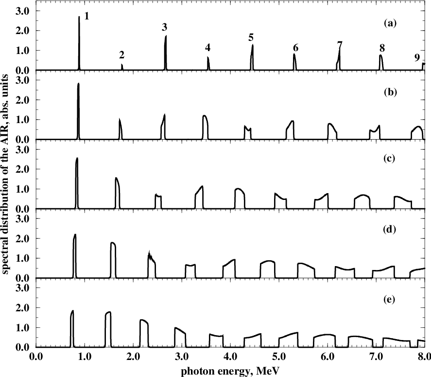
As the cone of emission becomes larger (the graphs (c)-(e) in the figures) the width of the peaks grows and their shape becomes asymmetric. The enhancement of the width follows from eq. (21) which connects the harmonics frequencies with the emission angle, and from figure 2. For a given number of the harmonic its frequency is the decreasing function of the emission angle, so that the center of the peak shifts towards lower values of the frequency as grows. Hence, the integration of (26) over the interval leads to the appearing of the emission within the frequency range where
We illustrate this estimate by figure 12, where the graphs (a)-(e) correspond to the contributions of different intervals of the emission angle to the spectral distribution of the AIR for 5 GeV positron in tungsten. It is clearly seen that each interval of corresponds to the emission radiated within particular ranges of .
In figures 10 and 11 the graphs (e) correspond to the value for the upper limit of integration over the emission angles. It is seen that initially well-separated narrow peaks (the graphs (a)) have merged, except for the first three harmonics. The further increase of up to produces the continuous spectrum of radiation although with the irregularities in the vicinities of .
7 Conclusions
In this work we have described the general formalism and the algorithm for effective calculations of the characteristics of the AIR as well as of the dechanneling length of positrons in periodically bent crystals.
The calculations performed in the present paper confirm the main result of our previous considerations concerning the possibility to create a powerful and easily tunable source of monochromatic radiation in the or/and range by means of crystalline undulator. They also demonstrate that the knowledge of the accurate values of the dechanneling lengths for various projectile energies, crystals and crystallographic palnes, and various parameters of the profile function is essential for obtaining reliable data on the intensity of the AIR.
The numeric results presented above refer to a particular shape of the bent channel which can be achieved by applying monochromatic transverse supersonic wave. However, both the formalism and the computer code allows to investigate, by comparatively simple means, the radiative spectra formed during the channeling of ultra-relativistic positrons along the crystallographic planes whose shape is described by arbitrary periodic shape function.
In this connection we want to mention the problem concerning the possibility to generate the AIR photons not in the range of up to several MeV but much higher. It can be achieved by using positron beams of higher energies, GeV. The increase of results in the increase of both the emitted photon energies and the dechanneling length. The latter leads to the increase in the intensity of the AIR. The obvious difficulty of the stable work of the crystalline undulator in this range of is in sharp increase of the radiative energy losses which are mainly due the ordinary channeling radiation. The radiative losses lead to a noticeable decrease of the projectile energy during the passage through the undulator. Hence, the use of the shape function with constant parameters and does not result in the intensive monochromatic undulator radiation. However, we believe, that this problem can be overcome by considering with the varied parameters, and . Then, provided the dependence () is known it is possible to adjust the parameters , so that the characteristic frequencies of the AIR will not change as the projectile penetrates through the crystal, and, therefore, the monochromaticity will be restored. This work is in progress at the moment and will become the subject of another publication in the near future.
The research was supported by DFG, GSI, and BMBF. AVK and AVS acknowledge the support from the Alexander von Humboldt Foundation.
References
References
- [1] Korol A V, Solov’yov A V, and Greiner W 1998 J.Phys.G.: Nucl. Part. Phys. 24 L45
- [2] Korol A V, Solov’yov A V, and Greiner W 1999 Int. J. Mod. Phys. E 8 49
- [3] Mikkelsen U and Uggerhøj E 2000 Nucl. Inst. and Meth. B 160 435
- [4] Kumakhov M A 1976 Phys. Lett. A57 17
- [5] Baryshevsky V G and Dubovskaya I Ya 1976 Dokl. Acad. Scie. USSR 231 113
- [6] Lindhard J 1965 Kong. Danske Vid. Selsk. mat.-fys. Medd. 34 14
- [7] Korol A V, Solov’yov A V, and Greiner W 2000 Int. J. Mod. Phys.
- [8] Krause W, Korol A V, Solov’yov A V, and Greiner W 2000 J.Phys.G.: Nucl. Part. Phys. 26
- [9] Beloshitsky V V and Kumakhov M A 1973 Dokl. Acad. Nauk. USSR 212 846
- [10] Waho T 1976 Phys. Rev. 14 4830
- [11] Beloshitsky V V, Komarov F F, and Kumakhov M A 1986 Phys. Rep. 139 293
- [12] Biruykov V M, Chesnokov Y A and Kotov V I 1996 Crystal Channeling and its Application at High-Energy Accelerators (Berlin: Springer)
- [13] Taratin A M 1998 Fiz. Elemment. Chastits i Atomnogo Yadra. 29 1063 (Engl. transl: 1998 Phys. Part. Nucl. 29 437)
- [14] Madey J M J 1971 J.Appl.Phys. 42 1906
- [15] Gemmell D S 1974 Rev. Mod. Phys. 46 129
- [16] Baier V N, Katkov V M, and Strakhovenko V M 1998 High Energy Electromagnetic Processes in Oriented Single Crystals (Singapore: World Scientific)
- [17] Kumakhov M A and Komarov F F 1989 Radiation From Charged Particles in Solids (New York: AIP)
- [18] Tsyganov E N 1976 Fermilab preprint TM-682, 684 (Batavia)
- [19] Ellison J A 1982 Nucl. Phys. A 206 205
- [20] 1987 Relativistic Channeling ed A Carrigan and J Ellison (NY: Plenum)
- [21] Solov’yov A V, Schäfer A and Greiner W 1996 Phys. Rev. E 53 1129
- [22] Baurichter A, et al 2000 Nucl. Inst. and Meth. B 164-165 27
- [23] Baryshevski V G 1982 Channeling, radiation and reactions in crystals at high-energies (Minsk: University Press)
- [24] Bazylev V A and Zhevago N K 1987 Radiation of Fast Charged Particles in Matter and External Fields (Moscow: Nauka)
- [25] Avakyan R O, Miroshnichenko I I, Murray J J,and Vigut T 1982 Zh. Eksp. Teor. Fiz. 82 1825 (Engl. transl. 1982 Sov.Phys. - JETP 55 1052)
- [26] Uggerhøj E 1983 Phys. Scripta 28 331
- [27] Bak J, et al 1985 Nucl. Phys. B 254 491
- [28] Uggerhøj E 1993 Rad. Effects and Defects in Solids 25 3
- [29] Dulman H D, et al 1993 Phys. Rev. B 48 5818
- [30]
Taratin A M and Vorobiev S A
1988
Nucl. Inst. and Meth. B 31 551
Taratin A M and Vorobiev S A 1989 Nucl. Inst. and Meth. B 42 41 - [31]
Arutyunov V A, Kudryashov N A,
Samsonov V M, and Strikhanov M N
1991 Zh. Tehn. Fiz. 61 1
Arutyunov V A, Kudryashov N A, Samsonov V M, and Strikhanov M N 1991 Zh. Tehn. Fiz. 61 32
Arutyunov V A, Kudryashov N A, Samsonov V M, and Strikhanov M N 1991 Nucl. Phys. B 363 283 - [32] Ginzburg V L 1947 Izv. AN SSSR 11 165
- [33] Barbini R, Ciocci F, Datolli G, and Gianessi L 1990 Riv. Nuovo Cim. 13 1
- [34] Ikezi H, Lin Liu Y R and Ohkawa T 1984 Phys. Rev. B 30 1567
- [35] Bogacz S A and Ketterson J B 1986 J. Appl. Phys. 60 177
- [36] Mkrtchyan A R, Gasparyan R A and Gabrielyan R G 1987 Zh. Eksp. Teor. Fiz. 93 432 (Engl. transl: 1987 Sov. Phys. – JETP 66 248)
- [37] Baryshevsky V G and Dubovskaya I Ya 1991 J. Phys. C: Cond. Matt. 3 2421
- [38] Dedkov G V 1994 Phys. Stat. Sol. (b) 184 535
- [39] Breese M B H 1997 Nucl. Inst. and Meth. B 132 540
- [40] Nakayama K, Sekimura M, Yanase I, Endo I, Takashima Y, Kaplin V, and Potylitsin A 1998 Nucl. Inst. and Meth. B 145 236
- [41] Avakyan R O, Gevorgyan L A, Ispiryan K A, and Ispiryan R K 1998 JETP Letters 68 467
- [42] Landau L D and Lifschitz E M 1992 Klassische Feldtheorie (Berlin: Akademie Verlag)
- [43] Ellison J A and Picraux S T 1981 Phys. Lett. A 83 271
- [44] Akhiezer A.I. and Berestetsky V.B. 1965 Quantum Electrodymanics (New York, Interscience)
- [45] Bonch-Osmolovskii A.G. and Podgoretskii M.I. 1978 Sov. J. Nucl. Phys. 29 216
- [46] Huang Z., Chen P., and Ruth D R 1996 Nucl. Inst. and Meth. B 119 192
- [47] Baier V N and Katkov V M 1997 Budker Institute, Preprint BUDKERINP-97-13 (Novosibirsk, IYF)
- [48]
Taratin A M, Filimonov Yu M, Vyatkin E G and Vorobiev S A
1980
Phys. Stat. Sol. (b) 100 273
Taratin A M and Vorobiev S A 1981 Phys. Stat. Sol. (b) 107 521
Taratin A M and Vorobiev S A 1986 Phys. Stat. Sol. (b) 133 511 - [49] Andersen J U, Bak J, and Bonderup E 1988 Nucl. Inst. and Meth. B 33 34
- [50] Biryukov V M 1995 Phys. Rev. E 51 3522
- [51] Berestetskii V B, Lifshitz E M, and Pitaevskii L P 1982 Quantum Electrodynamics (Oxford: Pergamon)
- [52] Komarov F F 1979 Phys. Stat. Sol. (b) 96 555
- [53] Rossi B 1952 High-Energy Particles (New York: Prentice-Hall, Inc.)
- [54] Sternheimer R M 1966 Phys. Rev. 145 247
- [55] Esbensen H and Golovchenko J A 1978 Nucl. Phys. A298 382
- [56] Caso C et al 1998 The European Physical Journal C3 The Review of Particle Physics
- [57] 1988 Press W H, Flannery B P, Teukolsky S A and Vetterling W T Numerical Recipies. The Art of Scientific Computing (Cambridge: University Press)
- [58] Kitagawa M and Ohtsuki Y H 1973 Phys. Rev. B 8 3117
- [59] Kovalenko A D, Mikhailov V A, Taratin A M, Boiko V V, Kozlov S I, and Tsyganov E N 1995 JINR Rapid Communications 72 9
- [60] McSkimin H J and Andreatch P, Jr 1964 J. Appl. Phys. B 35 3312
- [61] Mason W P 1972 Acoustic properties of Solids, American Institute of Physics Handbook, 3rd edn (New York: McGraw-Hill)