Analysis of Longitudinal Bunching in an FEL Driven Two-Beam AcceleratorThanks: The work at LBNL was performed under the auspices of the U.S. Department of Energy by University of California Lawrence Berkeley National Laboratory under contract No. AC03-76SF00098.
Abstract
Recent experiments [1] have explored the use of a free-electron laser (FEL) as a buncher for a microwave two-beam accelerator, and the subsequent driving of a standing-wave rf output cavity. Here we present a deeper analysis of the longitudinal dynamics of the electron bunches as they are transported from the end of the FEL and through the output cavity. In particular, we examine the effect of the transport region and cavity aperture to filter the bunched portion of the beam.
1 INTRODUCTION
Since 1995, free-electron laser (FEL) experiments at the CEA/CESTA facility have addressed the problem of the generation of a suitable bunched drive beam for a two-beam accelerator using linear induction accelerator technology. In these trials, a 32 period long bifilar-helix wiggler is coupled with a 35GHz, 5kW magnetron to provide an effective FEL interaction with the beam. Early experiments [2], [3] demonstrated optical diagnostic techniques to show bunching of the beam at the 35GHz FEL resonant frequency.
In the first cavity experiments [1], the induction linac ’PIVAIR’ was utilized, since its design energy of 7.2MeV is near optimum for a Ka-band two-beam accelerator based upon the relativistic-klystron mechanism [4]. During operation, PIVAIR delivered a 6.7MeV, 3kA, 60ns (FWHM) electron beam. The emittance out of the injector is approximately 1000 mm mrad, and the energy spread is less than 1% (rms) over the pulse length. The full current is collimated to 830 30A at the FEL entrance. Two 6-period adiabatic sections are used to inject the beam into the proper helical trajectory inside the wiggler, and then to release the beam back into the transport line afterwards.
After the wiggler follows a short transport beamline to capture and focus the beam through a narrow-aperture (4mm ID), 35GHz, single-cell rf output cavity [5]. The beamline consists of a section of stainless steel pipe (39mm ID, 1.2m long) with a set of solenoid magnets to provide focusing through the rf cavity. The rf power generated by the beam in the cavity is collected and analyzed, while the beam itself is dumped. This set-up is shown in Figure 1.

2 SIMULATION CODES
Two separate numerical simulation codes are used to model the system behavior. The first is the steady-state, 3-D FEL code, solitude [6]. The evolution of the FEL mode power, both as measured and as calculated by solitude, is shown (circles and solid line, respectively) in Figure 2. Also shown is the calculated value of the bunching parameter (dashed line) [7].

Not shown is the evolution of the beam current during transport through the wiggler. Experimentally, the current exiting the wiggler was observed to be 250 A. This value was reproduced in the FEL simulations [8].
The rks code [9] is then used to propagate the beam from the end of the wiggler through the cavity, and to calculate the interaction of the beam with the rf output structure. The 6D particle distribution of the beam at the end of the wiggler, as calculated by solitude, is used as input to rks. The evolution of the beam rms envelopes are shown in Figure 3.

The cavity acts as a collimator, reducing the beam current, as can be seen in Figure 4.

This degree of current loss was observed experimentally. The calculated power developed in the rf cavity is also comparable to that observed experimentally [1].
3 FILTERING AND BUNCH ENHANCEMENT
The interesting feature to observe in Figure 4, is the discontinuous growth of the bunching parameter, and simultaneous current loss, as the beam is partially focused through the cavity. This is preceded by the gradual loss of current, and the gradual increase in the bunching parameter in the transport region between the end of the wiggler and the entrance to the rf cavity. As was pointed out in [1], the transport line and cavity appear to act as a filter that preferentially selects the bunched portion of the beam for transmission. We seek to analyze this behavior in terms of the dynamics of the beam in the transport line following the wiggler.
The longitudinal phase space of the bunches near the middle of the beam pulse at the exit of the wiggler are shown in Figure 5. As shown, there is significant initial bunching (b 0.4) as well as ’tilt’ (energy-phase correlation). The presence of this tilt arises from the fortuitous extraction of the beam at an appropriate synchrotron oscillation phase in the ’saturated’ regime of the FEL interaction. This tilt contributes to continued bunching in a ballistic transport line. The effect of space charge forces upon debunching are limited by the low current (250 A) and high kinetic energy (6.7 MeV), and significant debunching will only appear after several meters [10]. This tilt can account for a modest rise in the bunching parameter, from 0.4 to 0.5, as discussed below.
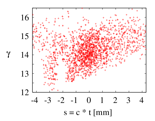
In addition to the energy tilt, the bunches emerging from the wiggler exhibit nonuniform bunching over the transverse distribution. This is shown in Figure 6.

Displayed are contours of constant bunching parameter as a function of transverse position. The transverse position coordinate has been normalized by the appropriate rms transverse beam size ( or ). While the average value of the bunching parameter is 0.4, there is a large degree of variation with the high-brightness, central core more strongly bunched than the outlying edges. Collimation of the beam can then strip away the less-bunched regions, resulting in an overall enhancement of the average bunching parameter.
The origin of the transverse variation can be related to the variation of the electromagnetic signal co-propagating with the beam in the waveguide of the FEL. Optical guiding studies [11] show that both the beam density and the electromagnetic mode amplitude decrease with increasing transverse distance from the beam axis. There is, then, a smaller coupling between the beam and the mode at distances from the beam axis, with the subsequent decrease in the forces responsible for bunching.
A series of simulations were performed in which the beam pipe radius of the transport line between the wiggler and rf cavity was varied. The purpose of this was to explore the relative influence of the two bunching effects described above. The results are shown in Figure 7, showing evolution of beam current and bunching parameter along the beamline.

As shown, the smaller pipes act as collimating agents, while the larger pipes transmit nearly 100% of the beam current from the wiggler to the entrance of the cavity. In the simulations, the smaller beam pipes allowed the less-bunched portions of the beam to be intercepted, thereby increasing the average bunching parameter. However, all simulations demonstrated ballistic bunching due to the energy-phase tilt. At the end of the transport line lies the cavity with a 2mm bore radius, which acts as a final collimator and limits drastically the percentage of transmitted current, while also stripping away the unbunched portions from the highly-bunched core. The final transverse distribution of the bunching parameter is shown in Figure 8, taken at the exit plane of the cavity.

This distribution exhibits a broader central plateau with a greater degree of bunching than seen in Figure 6.
4 CONCLUSIONS
We have presented results of simulations to assist in the analysis of experimental measurements of current and bunching transport in a high-frequency, two-beam accelerator prototype experiment. We have shown that the average degree of longitudinal bunching in a beam that exits an FEL amplifier can be improved by collimation. However, this may also be accompanied by significant loss of current.
5 REFERENCES
[1] T. Lefevre, et. al., Phys. Rev. Lett. 84 (2000), 1188.
[2] J. Gardelle, et. al., Phys. Rev. Lett. 76 (1996), 4532.
[3] J. Gardelle, et. al., Phys. Rev. Lett. 79 (1997), 3905.
[4] G. Westenskow, et. al., Proceedings of the VIII International Workshop on Linear Colliders, Frascati (1999).
[5] S.M. Lidia, et. al., Proceedings of the XIX International Linear Accelerator Conference, Chicago (1998), 97.
[6] J. Gardelle, et. al., Phys. Rev. E 50 (1994), 4973.
[7] The bunching parameter is defined as , where is the usual phase variable of an electron in the bunch, and where denotes the bunch ensemble average.
[8] S.M. Lidia, et. al., Proceedings of the 1999 IEEE Particle Accelerator Conference, New York (1999), 1797.
[9] S.M. Lidia, Proceedings of the 1999 IEEE Particle Accelerator Conference, New York (1999), 2870.
[10] J. Gardelle, et. al., Proceedings of the XIX International Linear Accelerator Conference, Chicago (1998), 794.
[11] A. Bhattacharjee, et. al., Phys. Rev. Lett. 60 (1988), 1254.