2FACE: Bi-Directional Face Traversal for
Efficient Geometric Routing
Abstract
We propose bi-directional face traversal algorithm to shorten the path the message takes to reach the destination in geometric routing. Our algorithm combines the practicality of the best single-direction traversal algorithms with the worst case message complexity of , where is the number of network edges. We apply to a variety of geometric routing algorithms. Our simulation results indicate that bi-directional face traversal decreases the latency of message delivery two to three times compared to single direction face traversal. The thus selected path approaches the shortest possible route. This gain in speed comes with a similar message overhead increase. We describe an algorithm which compensates for this message overhead by recording the preferable face traversal direction. Thus, if a source has several messages to send to the destination, the subsequent messages follow the shortest route. Our simulation results show that with most geometric routing algorithms the message overhead of finding the short route by bi-directional face traversal is compensated within two to four repeat messages.
1 Introduction
Geometric routing is an elegant approach to data dissemination in resource-constrained and large-scale ad hoc networks such as wireless sensor networks. Geometric routing is attractive because it does not require nodes to maintain, or the messages to carry, extensive state or routing information.
In geometric routing, each node knows its own and its neighbors’ coordinates. Using low-cost GPS receivers or location estimation algorithms [2], wireless sensor nodes can learn their relative location with respect to the other nodes and then use this information to make routing decisions. The message source node knows the coordinates of the destination node. The information that the message can carry should not depend on the network size. Each forwarding node should not maintain any extended routing data or keep any information about forwarded messages between message transmissions. The lack of infrastructure makes geometric routing algorithm a popular initialization and fallback option for other routing schemes. Thus, geometric routing optimization is of interest to the broad community of wireless sensor network designers.
Greedy routing [4] is an elementary approach to
geometric routing where the node selects the neighbor closest to the
destination and forwards the message there. The process repeats until
the destination is reached. Greedy routing fails in case the node is a
local minimum: it does not have neighbors that are closer to
the destination than itself. Alternatively, in compass routing
[7], a node selects the neighbor whose direction has the
smallest angle to the direction of the destination. Compass routing is
prone to livelocks.
GFG [1](also known as GPSR [6]) guarantees message delivery. GFG contains two parts. A node uses greedy routing to forward the message. To get out of local minimum, GFG switches to face traversal. In GFG, the message sequentially traverses faces that intersect the line from the source to destination node. The face traversal always proceeds in a fixed direction clockwise or counterclockwise. GFG may use two face traversal algorithms: FACE-1 and FACE-2. In FACE-1, the message goes around the entire face to find the adjacent face that is the closest to the destination. The message is then sent directly to this next face and the process repeats. In FACE-2, the message switches faces as soon as it finds the next face to traverse. The new face may not be closest to the destination and the message may have to traverse the same face multiple times. FACE-1 and FACE-2 have the respective worst case message complexity of and , where and are the set of vertices and edges in the network graph. Even though FACE-2 has worse message complexity, it proves to be more efficient in practice.
Datta et al [3] propose a number of optimizations to GFG. In particular, they propose that nodes maintain distance-two non-planar neighbors. If these nodes lie on the same face, the edge from the non-planar graph may be used as a shortcut to traverse the face. Kuhn et al [8] modify GFG to achieve asymptotically optimal worst-case message complexity. Nesterenko and Vora [9] propose a technique of traversing voids in non-planar graphs similar to face traversal. This traversal may be combined with greedy routing in similar to . A number of geometric (location-based) routing algorithms are proposed. The reader is referred to the following survey for a comprehensive list [5].
One of the shortcomings of face and void traversal is the possibility of producing a route that is far longer than optimal. The problem lies in the fixed traversal direction used in the existing algorithms. When routing along a face, the route in one direction may be significantly shorter than in the other. This is often the case when the message has to traverse the external face of the graph. We propose an algorithm 2FACE that accelerates the message propagation by sending the message to traverse the face in both directions concurrently. When one of the message encounters a face that is closer to the destination, the message spawns two messages to traverse the new face and continues to traverse the old face. When the two messages traveling around the face in the opposite direction meet, the traversal stops. The node memory and message-size requirements of 2FACE are the same as the other geometric routing algorithms. 2FACE improves worst-case time and message complexity of comparable single-direction algorithms. In practice, 2FACE guarantees faster message delivery to the destination but may require more messages. We present a technique to use 2FACE to determine the intermediate nodes to learn the preferred traversal direction. If source has multiple messages to send to the same destination, this technique can be used to eliminate the message overhead as the subsequent messages use the shorter path.
Paper contribution and organization. The rest of the
paper is organized as follows. We introduce our notation in
Section 2. We describe 2FACE and formally prove
it correct in Section 3. In Section 4, we
discuss how the algorithm can be adopted for greedy routing for use in
non-planar graphs and how algorithm can be used to select a preferred
route in multi-message sessions. We evaluate the performance of our
algorithm and its modifications in Section 5 and conclude
the paper in Section 6.
2 Preliminaries
Graphs. We model the network as a connected geometric graph . The set of nodes (vertices) are embedded in a Euclidean plane and are connected by edges . The graph is planar if its edges intersect only at vertices. A void is a region on the plane such that any two points in this region can be connected by a curve that does not intersect any of the edges in the graph. Every finite graph has one infinite external void. The other voids are internal. A void of a planar graph is a face.
Face traversal. Right-hand-rule face traversal
proceeds as follows. If a message arrives to node from its
neighbor , examines its neighborhood to find the node whose
edge is the next edge after in a clockwise
manner. Node forwards the message to . This mechanism results
in the message traversing an internal face in the counter-clockwise
direction, or traversing the external face in the clockwise
direction. Left-hand-rule traversal is similar, except the
next-hop neighbor is searched in the opposite direction. If node
(i) borders two faces and both of which intersect the
line and (ii) there is an edge adjacent to that borders and
and intersects , then is an entry point to
and . A source node is an entry point to the first face that
intersects . Notice that according to this definition, both
nodes adjacent to the edge that intersects are entry
points. To simplify the presentation we assume that only one of them
is an entry point while the other is a regular border node. However,
2FACE is correct without this assumption. Notice that a face
may intersect in multiple places and thus have multiple entry
points. Two faces that share an entry point are adjacent.
Geometric routing. A source node has a message to
transmit to a destination node . Node is aware of the Euclidean
coordinates of . Node attaches its own coordinates as well as
those of to the messages. Thus, every node receiving the message
learns about the line that connects the source and the
destination. Each message is a token, as its payload is
irrelevant to its routing. Depending on whether the token is routed
using right- or left-hand-rule, it is denoted as or . Each
node knows the coordinates of its neighbors: the nodes
adjacent to in .
Execution model. We assume that each node can send only
one message at a time. The node does not have control as to when the
sent message is actually transmitted. After the node appends the
message to the send queue , the message may be sent at arbitrary
time. Each channel has zero capacity; that is, the sent message is
removed from of the sender and instantaneously appears at the
receiver. Message transmission is reliable. The node may examine and
modify . We assume that manipulation, including its
modification and message transmission, is done atomically. We
assume that the execution of the algorithm is a sequence of atomic
actions. The system is asynchronous in the sense that the
difference between algorithm execution speed at each process is
arbitrary (but finite).
Complexity measures. The worst case message complexity
of an algorithm is the largest number of messages that is sent in a
single computation calculated in terms of the network parameters. The
worst case time complexity is the longest chain of causally related
messages in a computation. Where two messages are causally related if
the send of one message causally follows the receipt of the other.
3 2FACE Description and
Correctness Proof
Description. The pseudocode of 2FACE is shown in Figure 1. The operation of 2FACE is as follows. The source initiates the face traversal by sending the right- and left-hand rule tokens and to traverse the face that intersects the line. When a node receives token it first checks if it already has a matching . If there is a matching token, both tokens are removed and the processing stops. If the node is the destination, the token is delivered. Note that for the same of uniformity, the face traversal continues after delivery. If is an entry point to the adjacent face , initiates the traversal by sending and tokens to go around . After that, retransmits . Processing of the receipt of is similar to that of .
| node | ||||
| /* let be the face bordering | ||||
| and intersecting line | ||||
| add to | ||||
| add to | ||||
| node | ||||
| if receive then | ||||
| if then | ||||
| delete from | ||||
| else | ||||
| if then | ||||
| deliver | ||||
| elsif if an entry point to then | ||||
| add to | ||||
| add to | ||||
| add to | ||||
| if receive then | ||||
| /* handle similar to */ |

The operation of 2FACE is best understood with an example. Consider the graph shown in Figure 2. If node has a message to transmit to node , it sends and tokens around face . As a shorthand, we omit the source and destination and just specify the face that the token traverses. Nodes and forward without other actions. Node also forwards . However, is an entry point to an adjacent face . Thus, also sends and . Node forwards to . Meanwhile, also forwards to . Node is another entry point to and it sends another pair of tokens and to traverse . Node receives from and forwards it to . Node receives both and and deletes them. This completes the traversal of .
Notice that there are two pairs of tokens: , and , that traverse . Token is sent from to via and . At it meets where both tokens are destroyed. Token is forwarded from to and then to where is delivered. Token then continues to where it meets . Node destroys the pair and completes the traversal of .
Correctness proof.
Lemma 1
For each node bordering a face that intersects one of the following happens exactly once: either (a) receives token where is either or and forwards it or (b) has a token, receives a token from the opposite direction and deletes them both.
Proof:According to the algorithm, the token visits the node and proceeds to the next one along the face, or the two tokens in the opposing traversal directions meet at a node and disappear. Thus, to prove the lemma, we have to show that each node bordering face is reached and that it is visited only once. A sequence of adjacent nodes of the face is a visited segment if each node has been visited at least once. A border of a visited segment is a visited node whose neighbor is not visited. By the design of the algorithm, a border node always has a token to send to its neighbor that is not visited. Because we assume reliable message transmission, eventually the non-visited neighbor joins the visited segment. Thus, every node in a face with a visited segment is eventually visited.
Observe that the face bordering has at least one visited segment: the one that contains itself. Thus, every node in this face will eventually be visited. Because graph is connected, there is a sequence of adjacent faces intersecting from the face bordering to the face bordering . Adjacent faces share an entry point. When an entry point is visited in one face, it sends a pair of tokens around the adjacent face; that is, visiting an entry point creates a visited segment in the adjacent edges. By induction, all nodes in the sequence of adjacent faces are visited, including the destination node.
Let us discuss if a token may penetrate a segment and arrive at an interior (non-border) node. Observe that the computation of 2FACE starts with a single segment consisting of the source node. Thus, initially, there are no tokens inside any of the segments. Assume there are no internal tokens in this computation up to some step . Let us consider the next step. The token may penetrate the segment only through a border node or through an interior entry point. A token may arrive at a border node only from the border node of another segment of the same face. Because is a border node, it already holds the token of the opposite traversal direction. Thus, destroys both tokens and the received token does not propagate to the interior nodes. Let us consider an entry point node . Because is interior to the segment, it was visited earlier. Recall that a node is an entry point of two faces. When an entry point of a face receives a token, it creates a pair of tokens in the other face. That is, once an entry point is visited, it becomes visited in both faces. Since we assumed that there are no internal tokens up to step , cannot receive a token. By induction, a token may not penetrate a segment. That is, each node bordering a face is visited at most once. This completes the proof of the lemma.
The below theorem follows from Lemma 1.
Theorem 1
Algorithm 2FACE guarantees the delivery of a message from to .
According to Lemma 1, the total number of messages sent in a computation is equal to the sum of the edges of the faces intersecting . The causally related messages propagate along a path between and . Hence, the following corollary.
Corollary 1
The worst case message complexity of 2FACE is and time complexity is .
4 2FACE Application and
Extensions
Combining with greedy routing, using various traversals. For efficiency a single direction face traversal may be combined with greedy routing as in GFG [1]. Algorithm 2FACE can be used in a similar combination. We call the combined algorithm G2FG. The message starts in greedy mode and switches to 2FACE once it reaches a local minimum. Because multiple messages traverse the graph simultaneously, unlike GFG, once the message switches to face traversal in G2FG it continues in this mode until the destination is reached. A technique similar to 2FACE, can be used for bi-directional void traversal [9]. The resultant algorithm is 2VOID. 2VOID can also be combined with greedy routing to form G2VG.
Face traversal can be accelerated if each node stores its two-hop neighbors as proposed by Datta et al [3]. This method certainly applies to 2FACE.
Following the shortest path. The performance of
2FACE can be further optimized if the source has multiple
messages to send to the destination; that is, there is a
session between and . The idea is to route the messages
in a single direction and only along the shorter route of the
face. This path is called preferred. To enable this, the entry
point needs to be informed as to which traversal direction leads to
the shorter route to the destination. Algorithm 2FACE is
augmented by requiring each entry point to store the traversal
direction from which it was visited. The first message in the session
is sent using augmented 2FACE. When receives the message,
it sends a single traceback message in the opposite
direction. This traceback is to travel the preferred route in
reverse. When an entry point gets a traceback, it stores the
direction of its arrival and forwards it in the adjacent face in the
reverse direction from which it was first visited. Thus,
traceback reaches the source and every entry point learns the
preferred direction to forward messages of the session henceforth.
Note that some of the entry points may lie on the preferred path
altogether. A separate message sent using 2FACE has to inform
these entry points to discard the direction information. The last
message of the session that travels the preferred path has to make the
entry points forget about the preferred direction. Thus, following the
spirit of geometric routing, no information is stored at intermediate
nodes between sessions.
Let us go back to the example in Figure 2 to illustrate this idea. For this example, the route of the traceback message and the traversal directions for entry points and are shown in Figure 3. Also refer to the latter figure for the subsequent discussion. After the first 2FACE message, the entry points and store the preferred token arrival direction of and respectively. Destination receives the left-hand-rule token first. Node sends the traceback token . When traceback reaches , stores the preferred token forwarding direction as . Then, forwards the traceback token . When this token arrives at , learns that the direction of the preferred path is . For the rest of the session, will send messages to traverse using left-hand-rule until they reach . Node will forward them, also using left-hand-rule, until the messages reach . A message has to be sent using 2FACE to inform entry point (which does not lie on the preferred path) that entry point should not store direction information any longer.

5 Performance Evaluation
Simulation environment. We programmed the algorithms described in this paper using Java and Matlab. We used sets of randomly generated, connected unit-disk graphs starting with nodes and up to nodes with node increments in an area of by units.
In each graph, the nodes were uniformly distributed over the area. For each set of generated graphs we used the connectivity unit ranging from to : a pair of nodes was connected by an edge if the distance between them was less than . Disconnected graphs were discarded. For simulation we used an earlier version of FACE2 where the token waits for its pair at an entry point. On the generated graphs, the performance of this version and the one presented in the paper are identical. For each node density, graphs were generated for the experiments. Thus, the total number of graphs under consideration was graphs. For each graph, random node pairs were selected as sources and destinations. Example routes selected by GFG and G2FG are shown in Figure 4. In this example, the preferred path distance between the source and destination is hops for GFG and for G2FG.


Route length comparison. We compare the optimal
(shortest) route with the route generated by the single-direction and
bi-direction traversal algorithm. For the bi-direction traversal we
used the preferred path for route length calculation. For planar
graphs, we chose the more efficient FACE-2 for single-direction
traversal. For both kinds of traversals, we also compared the
performance of the greedy variants: GFG and G2FG. The
results are shown in Figure 5. We carried out the
same measurements for non-planar traversal algorithms. We chose
VOID-2 as a single-direction traversal algorithm. The results
are shown in Figure 6. We incorporated the 2-hop
shortcut optimization to traversal suggested by Datta et al
[3]. The results are shown in Figure 7. As the
results indicate, for all geometric routing algorithms studied, the
bi-directional traversal outperforms the single-directional one by a
factor of or . Moreover, the path length of the bi-directional
traversal approaches the shortest (optimal) path in the graph. To
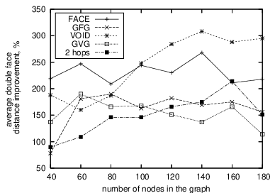
highlight the performance improvement, we plotted the difference
between the paths selected by single- and bi-directional traversals
normalized to the bi-directional traversal path length. The plot is in
Figure 8. The plot does not show an observable trend,
but the path improvement is consistent across the graph densities and
and across different routing algorithms.


The concurrent message transmission in bi-directional traversal requires more messages than in in single direction. We quantify this message overhead in Figure 9. In the first graph, we plat the message difference between the two traversal types. Observe that the preferred route selected by bi-directional traversal is several times shorter on average. Thus, if source have multiple messages to send to the destination, the subsequent messages can use this shorter route as opposed to the route selected by the single-directional traversal. The second graph in Figure 9 indicates how many messages per session it takes to compensate this overhead. The figure indicates that for some routing algorithms the overhead may be recouped by a session as short as just two messages.


6 Conclusion
In this paper, we proposed the bi-directional face traversal to improve geometric routing efficiency. The results show that the proposed algorithm provides significant performance improvement over existing single-face traversal. Moreover, the bi-directional traversal addresses one of the major drawbacks of geometric routing: its inconsistency due to selection of disadvantageous routes. The proposed technique is simple to implement. The authors are hopeful that it will find its way into the practical implementation of routing algorithms.
References
- [1] P. Bose, P. Morin, I. Stojmenovic, and J. Urrutla. Routing with guaranteed delivery in ad hoc wireless networks. The Journal of Mobile Communication, Computation and Information, 7(6):48–55, 2001.
- [2] N. Bulusu, J. Heidemann, D. Estrin, and T. Tran. Self-configuring localization systems: Design and experimental evaluation. ACM Transactions on Embedded Computing Systems, (1):24–60, February 2004.
- [3] S. Datta, I. Stojmenovic, and J. Wu. Internal node and shortcut based routing with guaranteed delivery in wireless networks. Cluster Computing, 5(2):169–178, April 2002.
- [4] G.G. Finn. Routing and addressing problems in large metropolitan-scale internetworks. Technical Report ISI/RR-87-180, March 1987.
- [5] S. Giordano, I. Stojmenovic, and L. Blazevic. Position based routing algorithms for ad hoc networks - a taxonomy. Ad Hoc Wireless NetWorking, pages 103–136, January 2004.
- [6] B. Karp and H.T. Kung. GPSR: Greedy perimeter stateless routing for wireless networks. In Proceedings of the Sixth Annual ACM/IEEE International Conference on Mobille Computing and Networking (MobiCom 2000), pages 243–254. ACM Press, August 2000.
- [7] E. Kranakis, H. Singh, and J. Urrutia. Compass routing on geometric networks. In Proc. 11 th Canadian Conference on Computational Geometry, pages 51–54, Vancouver, August 1999.
- [8] F. Kuhn, R. Wattenhofer, Y. Zhang, and A. Zollinger. Geometric ad-hoc routing: Of theory and practice. 22nd ACM Symposium on the Principles of Distributed Computing (PODC), July 2003.
- [9] A. Vora and M. Nesterenko. Void traversal for guranteed delivery in geometric routing. The 2nd IEEE International Conference on Mobile Ad-hoc and Sensor Systems (MASS 2005), pages 63–67, November 2005.