[orcid=0000-0002-0090-4486]
[orcid=0000-0001-5913-1070]
Spiral motion enables simultaneous homogenization
and enhanced transport in granular pipe flow
Abstract
Density waves in gravity-driven granular pipe flow reduce transport efficiency and produce large fluctuations in the local solid fraction. Helical wall textures suppress these instabilities but at the expense of reduced throughput. Using discrete element simulations (DEM), we find that this homogenization is associated with spiral particle motion induced by the helical wall texture. Quantifying this motion by the mean angular velocity reveals a strong correlation between spiral motion, flow homogenization, and transport performance. Motivated by this insight, we introduce a helical pipe whose centerline follows a helical path while maintaining a constant circular cross section. This design generates stronger spiral motion than conventional helical wall textures. For suitable design parameters, the helical pipe simultaneously enhances flow homogeneity and increases the mean flow velocity beyond that of a plain straight pipe. These results support spiral motion as a useful diagnostic and design variable for simultaneously improving flow homogeneity and transport efficiency within the investigated parameter range.
keywords
granular pipe flow ,density waves ,helical wall texture ,helical pipe ,passive flow control ,flow instability,discrete element method (DEM)1 Introduction
Gravity-driven granular pipe flow is prone to the formation of density waves, i.e., alternating dense plugs and dilute regions, which reduce transport efficiency and result in inhomogeneous particle flow. Suppressing these instabilities is an important objective in the design of efficient granular conveying systems. Such density waves have been studied experimentally, numerically and theoretically for several decades [1, 2, 3, 4, 5, 6, 7, 8, 9, 10]. Granular transport through vertical pipes and narrow channels is encountered in numerous industrial processes, including mining, chemical engineering and bulk solids handling [11, 12, 13, 14, 15, 16].
Various approaches have been proposed to suppress density waves. In this work, we use the term passive flow control to describe flow modification achieved solely by modifying the conveying pipe, without external actuation or additional energy input. Passive flow-control strategies are attractive because they improve flow behavior without increasing the complexity or energy demand of the conveying process. In contrast, active flow-control methods, such as mechanical vibration [17] or electric fields [18], require external energy input and may not be applicable in all industrial settings.
Previous studies have therefore explored passive flow-control strategies for clogging reduction and flow homogenization [19, 20, 21, 9]. Among these approaches, helical wall textures have been shown to be particularly effective. Verbücheln et al. [20, 21] demonstrated that a helical texture on the inner wall of a vertical pipe substantially suppresses density waves. Their results further suggested an apparent trade-off between flow homogeneity and transport efficiency: increasing the strength of the helical wall texture improves homogenization but reduces the mass flow rate, as reflected by a modified Beverloo relation [22, 11, 12, 23, 24].
Although helical wall textures have been shown to suppress density waves, previous studies focused primarily on the resulting axial solid-fraction distribution and transport rate. The particle-scale motion associated with this homogenization has not been identified systematically. The resulting unresolved relationship between pipe shape, particle motion, flow homogeneity, and transport velocity constitutes the research gap addressed in the present work.
In this work, we use three-dimensional discrete element simulations to test whether spiral particle motion is systematically associated with passive flow homogenization. We quantify the spiral component by the mean angular velocity and compare it with the axial solid-fraction fluctuations and mean transport velocity. For this purpose, we compare a plain reference pipe, a helically textured pipe, and a helical pipe under otherwise identical simulation conditions.
The term mechanism is used here in an operational, particle-resolved sense. We do not attempt to derive a closed hydrodynamic description of the granular flow. Such a derivation would require constitutive relations for stress, dissipation, frictional transport, particle rotation, and the effective boundary conditions at the textured or curved wall. A generally accepted closed description containing these ingredients is not available for the present three-dimensional, dissipative, and frictional flow. Instead, we use controlled DEM comparisons to identify relationships between pipe shape, particle motion, and flow homogenization within the investigated parameter range.
Motivated by the relationship observed for the helically textured pipe, we introduce a helical pipe whose centerline follows a helical path while maintaining a constant circular cross section. Unlike the textured pipe, this shape contains no discrete wall asperities. Within the investigated range of helix periods, the helical pipe produces stronger spiral particle motion and can simultaneously improve flow homogeneity and transport efficiency.
The following sections describe the numerical model and flow characterization, present the results for the two passive flow-control concepts, and summarize the principal conclusions.
2 Simulation setup and numerical model
2.1 Granular flow through passive flow-control pipes
We consider gravity-driven flow of spherical particles through a vertical pipe of radius and length . The simulations consider a plain reference pipe without passive flow-control modifications, a helically textured pipe, and a helical pipe whose centerline follows a helical path while maintaining a constant circular cross section (Fig. 1). The influence of the respective helix period is investigated systematically.


The helical wall texture consists of fixed spherical wall elements of radius arranged along a helix with period and spacing , attached to the inner pipe wall. In the helical pipe configuration, the pipe centerline follows a helical path while the pipe maintains a constant circular cross section. Unless stated otherwise, all configurations share identical pipe dimensions and operating conditions.
The flowing particles are monodisperse spheres with radius . The use of spherical particles isolates the influence of pipe shape from additional particle-shape effects. In particular, the present model does not include shape-induced interlocking or the enhanced rotational resistance that can occur for angular or elongated particles. Initially, particles are distributed randomly inside the pipe such that the prescribed solid fraction
| (1) |
is obtained. Each particle is assigned a small random radial velocity in the interval . Particle motion is driven solely by gravity acting in the negative direction, where the -axis is the vertical axis of the simulation domain. Periodic boundary conditions are imposed in the direction, resulting in statistically stationary flow after an initial transient. All simulations consider a vertical pipe under terrestrial gravity. Pipe inclination and gravity level are not varied, and the conclusions are therefore restricted to this configuration.
Unless stated otherwise, the simulation parameters listed in Table 1 are used throughout this work.
| parameter | value | |
| particle material density | ||
| gravitational acceleration | ||
| Young’s modulus of the particles | 0.1 GPa | |
| Poisson ratio of the particles | 0.24 | |
| dissipative constants | ||
| particle-particle normal | ||
| particle-wall normal | ||
| particle-texture normal | ||
| particle-particle tangential | ||
| particle-wall tangential | ||
| particle-texture tangential | ||
| particle-particle friction coefficient | 0.5 | |
| particle-wall friction coefficient | 0.5 | |
| radius of flow particles | 0.6 mm | |
| solid fraction of flow particles | 0.13 | |
| pipe length (periodic bc) | ||
| pipe radius | ||
| radius of texture particles | ||
| distance of texture particles | ||
| limits of initial random velocity | 0.1 m/s |
2.2 DEM simulation
The particle dynamics are simulated using the Discrete Element Method (DEM), as implemented in MercuryDPM [25]. The same contact model is employed for particle–particle and particle–wall interactions, combining a viscoelastic Hertzian normal contact force [26] with a modified Cundall–Strack tangential contact force [27, 28].
The normal interaction force between two particles of radii and , located at and , acts along the unit vector and has the magnitude
| (2) |
where is the mutual deformation and . The Young’s modulus, , and the Poisson ratio, , are material properties specified in Table 1. The dissipative parameter is determined from the universal relation between the velocity-dependent coefficient of restitution and the dimensionless impact velocity [26, 29, 30, 31]. It differs for particle–particle, particle–wall, and particle–texture collisions. Numerically inverting this expression [32] and assuming the coefficient of restitution of at an impact velocity of , we obtain the values given in Table 1.
The tangential interaction force acts in the direction of the projection of the relative particle velocity onto the contact plane and is given by
| (3) |
where denotes either or , depending on the interacting pair, is the relative tangential velocity at the contact point, and
| (4) |
denote the shear modulus and the tangential dissipative parameter [9], respectively. Thus, is not an independently selected simulation parameter but follows from , , and . As in the case of , differs for particle–particle, particle–wall, and particle–texture collisions. The term containing describes the dissipative contribution to the tangential contact force. The integral in Eq. 3 is performed over the duration of the contact, .
The Young’s modulus corresponds to hard rubber or plastics like low-density polyethylene. All pipe configurations are compared using the same Young’s modulus and contact model. The comparison therefore isolates the influence of pipe shape under identical numerical stiffness conditions. However, no systematic stiffness sensitivity study was performed, and the present results do not demonstrate that the density-wave dynamics are independent of .
The same Coulomb friction coefficient, , is used for particle–particle and particle–wall contacts. Because particle–wall friction directly affects the transfer of angular momentum from the wall to the particle flow, the quantitative results may depend on both friction coefficients. No systematic friction-sensitivity study was performed; the conclusions are therefore restricted to the values reported here.
The equations of motion are integrated using a time step of . For the reference parameters, the Rayleigh time [33] is estimated as
| (5) |
Using the parameters listed in Table 1, we obtain and therefore . The integration time step is thus substantially smaller than the Rayleigh time and satisfies the commonly used stability criterion for DEM simulations. This estimate verifies the stability of the selected time step but does not constitute a time-step independence study. A systematic time-step refinement study was not performed for the present data set.
All particle positions, velocities, and forces are evaluated in the inertial laboratory frame. The equations of motion contain gravity and the particle-particle and particle-wall contact forces described above. The influence of the pipe shape enters through the particle-wall contact forces. No rotating or centerline-following reference frame is introduced; consequently, no centrifugal or Coriolis forces appear in the equations of motion.
2.3 Flow characterization
To quantify the effect of passive flow control, we evaluate three quantities: the mean flow velocity, the standard deviation of the local solid fraction, and the mean angular velocity of the particle flow. The first two characterize transport efficiency and flow homogeneity, whereas the latter quantifies the intensity of spiral particle motion.
The mean flow velocity is obtained by averaging the axial particle velocity over all flowing particles, followed by a time average after the flow has reached a statistically stationary state.
Flow homogeneity is quantified by the standard deviation of the local solid fraction. To this end, the pipe is divided into sections of equal length along the pipe axis. The local solid fraction of section is computed as
| (6) |
where denotes the volume of particle contained within section . The standard deviation of is then calculated and averaged over time after the flow has reached a statistically stationary state. Because the simulations employ periodic boundary conditions, they have no inlet or outlet from which a conventional residence-time distribution could be determined. Furthermore, all particles have the same size and material properties, so particle segregation is not defined for the present monodisperse system. The local solid-fraction measure instead quantifies axial flow uniformity throughout the periodic domain.
To quantify the intensity of spiral particle motion, we evaluate the mean angular velocity about the vertical pipe axis,
| (7) |
where and is the radial position of particle relative to the vertical pipe axis.
The mean angular velocity is a kinematic diagnostic and is not itself a conserved quantity. The total angular momentum of the particle system about the vertical axis is
| (8) |
where and denote the moment of inertia and spin angular velocity of particle . Its balance is
| (9) |
where is the position of wall contact and is the corresponding force acting on the particle. Gravity produces no torque about the vertical axis, and particle–particle contact contributions cancel in the balance of the complete particle system. Thus, particle–wall contacts provide the external torque, while the wall shape determines its axial component. The present simulations quantify the resulting spiral motion through ; a contact-resolved quantitative torque budget was not evaluated.
3 Results
3.1 Flow homogenization by helical wall textures
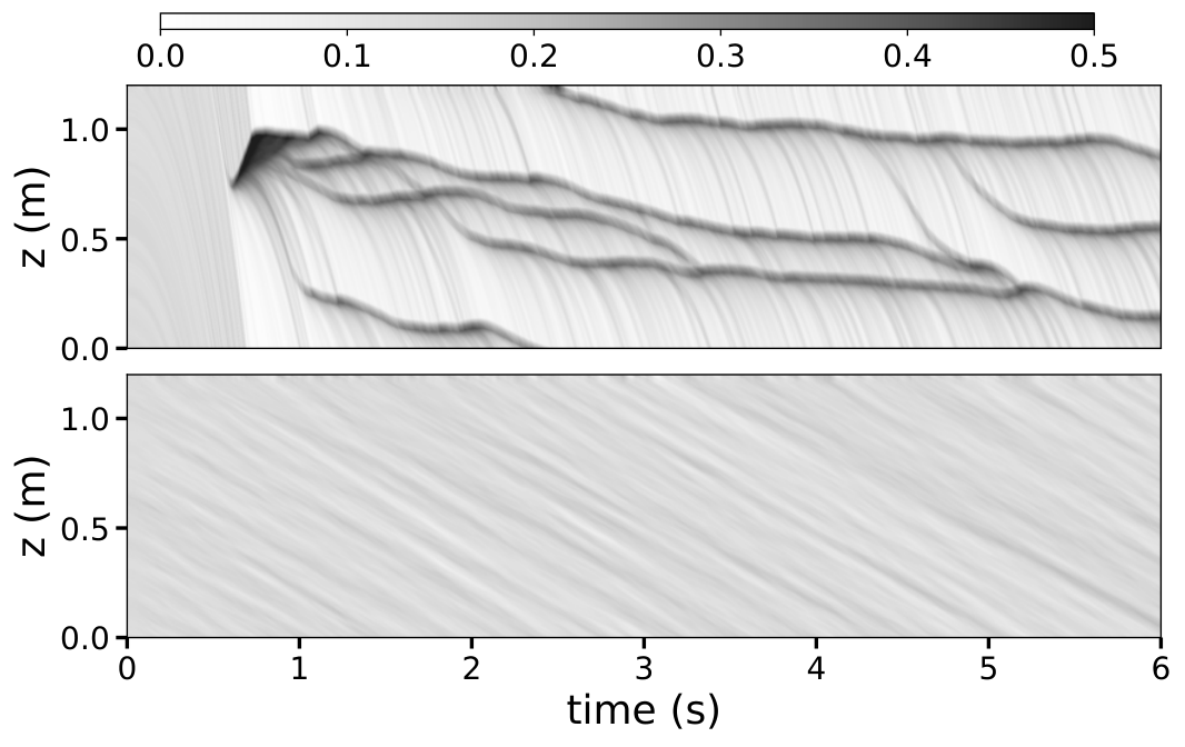
compares the spatio-temporal evolution of the local solid fraction in the plain reference pipe and a pipe with a helical wall texture. In the plain pipe, pronounced density waves develop in the form of alternating dense plugs and dilute regions. These plugs propagate along the pipe and produce large temporal and spatial fluctuations of the local solid fraction. In contrast, the helical wall texture largely suppresses the formation of dense plugs, resulting in a considerably more homogeneous particle flow.
The pronounced difference between the two flow patterns demonstrates that a helical wall texture effectively suppresses density-wave formation in gravity-driven granular pipe flow. While this homogenizing effect has previously been reported [20, 21], the physical mechanism responsible for it has remained unclear. Since the wall texture imposes a helical path on particles moving close to the wall, a natural hypothesis is that the induced spiral particle motion governs the observed homogenization. In the following section, we examine this hypothesis by systematically relating the intensity of spiral motion to both flow homogeneity and transport performance.
3.2 Spiral motion and flow homogenization
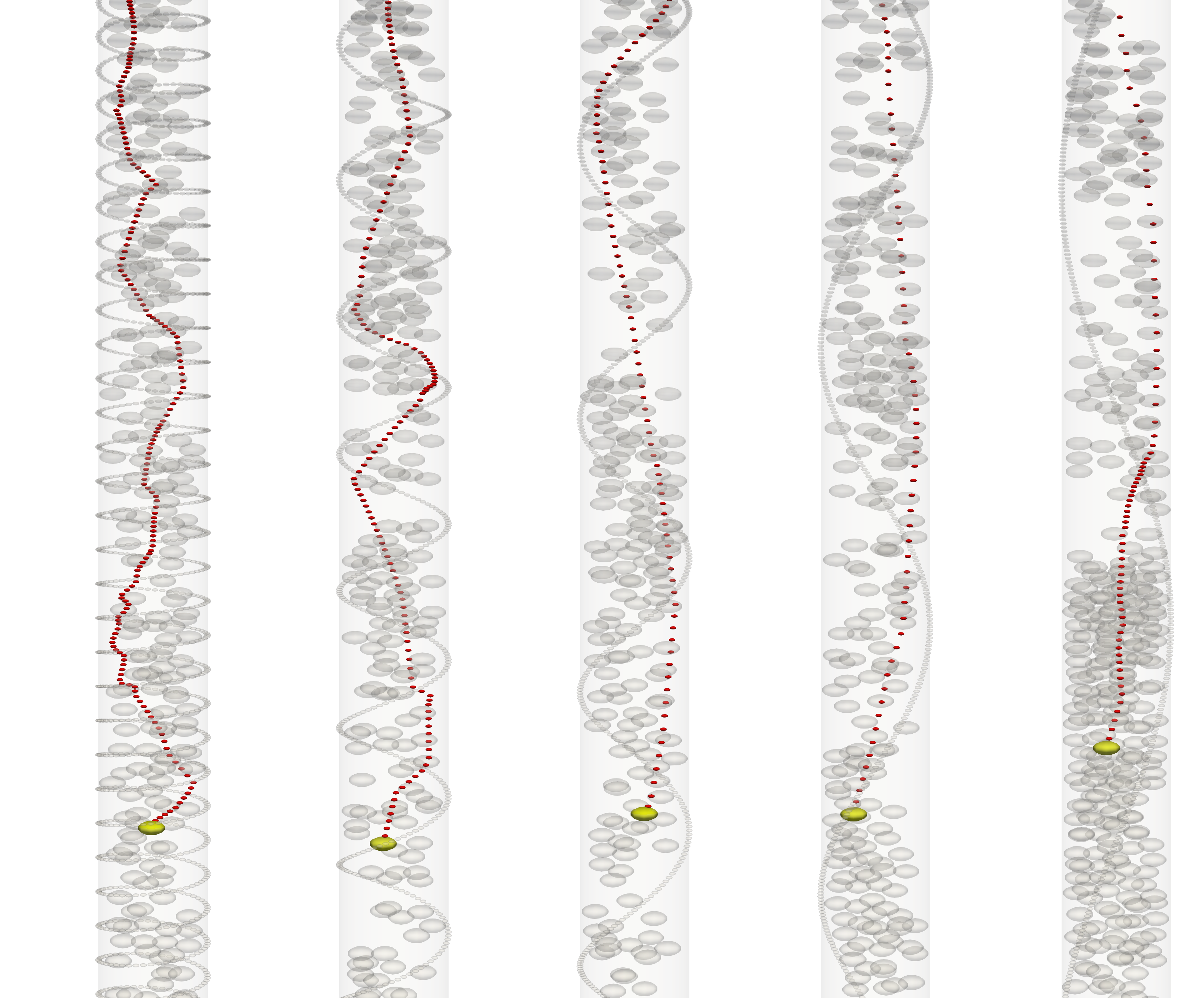
To investigate the role of spiral motion in passive flow control, we systematically vary the helix period of the wall texture. Figure 3 shows typical flow patterns in the pipe with helix wall texture different periods. At , particles flow with very limited spiral motion, and the flow hardly follows the periodicity of the helical wall texture. As increases to , the flow develops more spiral motion. Although the flow still spirals at a longer period than that of the corresponding wall texture, the particle trajectory appears smoother. As further increases to , plugs form, hindering the spiral motion.
For each helix period, the mean angular velocity, the standard deviation of the local solid fraction, and the mean flow velocity are evaluated as described in Section 2.3. Figure 4 summarizes the dependence of these quantities on the helix period. Each data point shown represents the mean and standard deviation obtained from 5 independent simulations with different random initial particle positions and velocities.
Figure 4a shows that the mean angular velocity strongly depends on . As the helix period increases, the angular velocity first rises, reaches a maximum for , and decreases for larger helix periods. Thus, the helix period directly controls the intensity of the induced spiral motion.
The standard deviation of the local solid fraction exhibits the opposite trend (Figure 4b). It remains small for helix periods up to , indicating a homogeneous particle flow, but increases rapidly for larger helix periods as density waves reappear. The strong inverse correlation between the standard deviation of the local solid fraction and the mean angular velocity shows that stronger spiral motion is consistently associated with the suppression of density waves over the investigated range of helix periods.
The mean flow velocity (Figure 4c) initially increases with increasing helix period, reaches a maximum near , and subsequently approaches the value of the reference pipe. Although strong spiral motion promotes flow homogenization, it does not lead to the highest transport velocity. Instead, the maximum flow velocity remains below that of the reference pipe.
These results support spiral particle motion as a particle-scale feature associated with flow homogenization in helically textured pipes. Stronger spiral motion is accompanied by reduced density-wave formation, whereas the wall texture used to generate this motion also increases particle-wall interactions and the associated energy dissipation. The transport performance therefore results from a competition between these two effects. Consequently, an optimal helix period exists at which the flow is effectively homogenized while the additional flow resistance remains small. This finding motivates the search for alternative passive flow-control concepts that generate spiral motion more efficiently. A comparison with randomly distributed wall elements is included in the Appendix, Appendix A.
3.3 Helical pipe
The previous section shows that spiral particle motion effectively suppresses density waves, but that the helical wall texture required to generate this motion also introduces additional flow resistance. This suggests that improved passive flow control may be achieved by generating spiral motion without modifying the pipe wall. We therefore investigate a helical pipe whose centerline follows a helical path while maintaining a constant circular cross section.

Figure 5 illustrates the pipe design. The shape of the pipe is characterized by the helix radius and the helix period . By construction, the helix radius equals of the pipe radius, , and is therefore not an independent parameter of the present pipe design. The geometric parameter varied in this study is the helix period ; the pipe diameter and particle properties are kept constant.
The pipe shape is generated using a computer-aided design (CAD) model and imported into MercuryDPM as triangulated walls. Unless stated otherwise, the same material parameters, contact model, and operating conditions as described in Section 2 are used. To ensure periodicity, the helix period is chosen such that the pipe height is an integer multiple of .
DEM does not employ a computational volume mesh. However, the curved wall of the helical pipe is represented by a triangulated surface. A systematic triangulation-refinement study was not performed, and numerical independence with respect to the wall discretization is therefore not claimed.
Figure 6 shows typical flow patterns in the helical pipe at different periods. In contrast to the helically textured pipe, the helical pipe contains no discrete wall asperities. The observed spiral motion results from particle interactions with the smooth curved wall represented in the DEM model. The resulting spiral motion is visibly stronger and extends across the entire pipe cross section.

3.4 Comparison of passive flow-control concepts
Motivated by the previous results, we compare the performance of the helical pipe with that of the helical wall texture. Figure 7 summarizes the mean angular velocity, the standard deviation of the local solid fraction, and the mean flow velocity for both passive flow-control concepts as functions of the helix period.
Figure 7a shows that the helical pipe generates a greater angular velocity than the helical wall texture, particularly for helix periods in the range . While the helical wall texture fails to maintain spiral particle motion as the helix period increases, modifying the pipe centerline continues to induce strong spiral motion.
The stronger spiral motion is accompanied by a pronounced reduction in the standard deviation of the local solid fraction (Figure 7b). Throughout the range of helix periods for which the angular velocity is increased, the helical pipe consistently produces a more homogeneous particle flow than the helical wall texture. These results further support the conclusion that spiral particle motion is closely related to flow homogenization.
The corresponding mean flow velocity is shown in Figure 7c. For the simulated helix periods , the helical pipe simultaneously produces a lower mean solid-fraction standard deviation and a higher mean flow velocity than the straight reference pipe. This interval is the demonstrated operating range for simultaneous improvement within the investigated parameter set; it should not be interpreted as a universal design range. The maximum flow velocity is obtained for .
Because the gravitational acceleration and the prescribed particle–wall friction coefficient are identical in all simulations, the velocity increase cannot result from changes in these parameters. As explained in Section 2.2, the calculations are performed in the inertial laboratory frame and contain no centrifugal force. The increase is associated with modified particle–wall interactions and reduced plug formation, although a quantitative energy and collision budget was not evaluated.
For the helical pipe, the nearly constant angular velocity and the linear dependence of the mean flow velocity on (for ) indicate that particles rotate in sync with the helix period. Extracting the constant in the angular velocity and the slope in the mean flow velocity from Figure 7, we compute the spatial frequency —the number of particle rotations per unit distance traveled:
| (10) |
Thus, the particles complete approximately one rotation over each axial distance .
As increases further above , the formation of plugs disrupts the flow pattern, leading to a reduction in angular velocity. At the same time, the mean flow velocity decreases, while the standard deviation of the solid fraction increases toward the value observed in the reference pipe.
The comparison demonstrates that the previously observed trade-off between flow homogenization and transport efficiency is not an inherent consequence of spiral particle motion. The helically textured pipe is straight and generates spiral motion through discrete wall elements, whereas the helical pipe has a curved centerline and no discrete wall asperities. Because both configurations use the same contact parameters and particle–wall friction coefficient, the comparison shows that pipe curvature can generate spiral motion and simultaneous performance improvement without helical wall roughness. The present data do not, however, provide a quantitative decomposition of all curvature- and collision-related contributions.
Particle–wall collision frequency, impact intensity, and wall wear were not evaluated. Stronger transverse particle motion may increase wall loading, and this practical trade-off must be examined before industrial application. Computational-cost and scaling data were likewise not retained. Although all configurations use the same number of particles and contact model, the helical pipe employs a triangulated CAD wall, whereas the straight and helically textured pipes use simpler wall representations. Quantitative computational benchmarking, wear analysis, and experimental validation therefore remain necessary.
4 Conclusion
In this work, we investigated the mechanism by which passive flow-control concepts suppress density waves in gravity-driven granular pipe flow. Using discrete element simulations, we found a consistent relationship between spiral particle motion and the suppression of density waves.
The analysis of helically textured pipes showed that increasing spiral motion improves flow homogeneity but does not necessarily increase transport performance. Although an appropriately chosen helix period effectively suppresses density waves, the wall texture required to generate spiral motion also increases particle–wall interactions and the associated energy dissipation. Consequently, the transport performance results from a competition between enhanced flow homogenization and the additional resistance introduced by the wall texture.
Motivated by this observed relationship, we introduced a helical pipe whose centerline follows a helical path while maintaining a constant circular cross section. In contrast to the helically textured pipe, the helical pipe generates spiral motion through particle interactions with a smooth curved wall rather than with discrete wall asperities. As a result, substantially stronger spiral motion is achieved over a wide range of helix periods. This leads to both a lower standard deviation of the local solid fraction and a higher mean flow velocity. In particular, the maximum transport velocity exceeds that of both the helical wall texture and the reference pipe.
These findings demonstrate that the previously observed trade-off between flow homogeneity and transport efficiency is not an intrinsic consequence of spiral particle motion. Instead, it arises from the specific passive flow-control concept used to generate this motion. The present results suggest spiral particle motion as a useful diagnostic and possible design variable for passive flow control in granular pipe flow. Future studies should determine whether passive flow-control concepts can be improved by increasing spiral particle motion while limiting the accompanying flow resistance.
Appendix
Appendix A Comparison with random wall textures
To assess whether the observed flow homogenization is a consequence of the helical arrangement rather than wall roughness alone, we compare the helical wall texture with randomly distributed wall elements. Following Verbücheln et al. [20], the random textures are generated using the same number of wall elements as the corresponding helical textures.
shows the standard deviation of the local solid fraction and the mean flow velocity as functions of the number of wall elements. When the number of wall elements is greater than , although the random wall texture maintains a slightly smaller flow homogeneity, it results in a much lower mean flow velocity than the helix wall texture. Reducing the number of randomly distributed wall elements below increases the mean flow velocity, but simultaneously deteriorates flow homogeneity. Consequently, random wall textures cannot achieve the combination of efficient transport and effective flow homogenization obtained with helical wall textures.
Funding
This work was funded by the Deutsche Forschungsgemeinschaft (DFG, German Research Foundation) – project number 398618334. The funder had no involvement in the study design, analysis and interpretation of the results, preparation of the manuscript, or decision to submit it for publication.
Declaration of competing interest
The authors declare no financial or personal relationships that could have influenced the research presented in this article.
Data availability
The simulation data underlying the results presented in this article are available from the corresponding author upon request.
Declaration of generative AI and AI-assisted technologies in the manuscript preparation process
During the preparation of this work, the authors used ChatGPT for English language improvement. The authors reviewed and edited the output as needed and take full responsibility for the content of the published article.
References
- [1] (1994) Recurrent clogging and density waves in granular material flowing through a narrow pipe. Journal de Physique I 4, pp. 499–506. External Links: Document Cited by: §1.
- [2] (1998) 4/3 law of granular particles flowing through a vertical pipe. Physical Review Letters 80, pp. 2833. External Links: Document Cited by: §1.
- [3] (1999) Experimental study of a granular flow in a vertical pipe: A spatiotemporal analysis. Physical Review E 59, pp. 778–786. External Links: Document Cited by: §1.
- [4] (2006) Plug conveying in a vertical tube. Powder Technology 162, pp. 16–26. External Links: Document Cited by: §1.
- [5] (1997) Langevin equation approach to granular flow in a narrow pipe. Journal of Statistical Physics 86, pp. 421–430. External Links: Document Cited by: §1.
- [6] (2002) Density waves in gravity-driven granular flow through a channel. Physics of Fluids 14, pp. 3309–3326. External Links: Document Cited by: §1.
- [7] (2010) Model for density waves in gravity-driven granular flow in narrow pipes. Physical Review E 81, pp. 061302. External Links: Document Cited by: §1.
- [8] (2020) Clogging-jamming connection in narrow vertical pipes. Physical Review E 102, pp. 010902. External Links: Document Cited by: §1.
- [9] (2025) Particle size segregation in granular pipe flow. Chaos 35, pp. 043137. External Links: Document Cited by: §1, §1, §2.2.
- [10] (2025) Discrete element simulation of dry adhesive granular flow in a vertical pipe. Powder Technology 460, pp. 121079. External Links: Document Cited by: §1.
- [11] (1961) The flow of granular solids through orifices. Chemical Engineering Science 15, pp. 260–269. External Links: Document Cited by: §1, §1.
- [12] (1982) Flow of granular materials – I: Discharge rates from hoppers. Chemical Engineering Science 37, pp. 1597–1609. External Links: Document Cited by: §1, §1.
- [13] (2005) Ore pass practice in Canadian mines. Journal of the Southern African Institute of Mining and Metallurgy 105, pp. 809–816. External Links: Document Cited by: §1.
- [14] (2013) Pipe transport in underground mining: An experimental approach. AIP Conference Proceedings 1542, pp. 710–713. External Links: Document Cited by: §1.
- [15] (1995) Effect of gravity on mass flow rate in an hour glass. Powder Technology 85, pp. 279–281. External Links: Document Cited by: §1.
- [16] (2001) Jamming of granular flow in a two-dimensional hopper. Physical Review Letters 86, pp. 71–74. External Links: Document Cited by: §1.
- [17] (1999) Effects of horizontal vibration on hopper flows of granular materials. Physics of Fluids 11, pp. 68–75. External Links: Document Cited by: §1.
- [18] (2001) Granular flows through vertical pipes controlled by an electric field. Physical Review E 64, pp. 061305. External Links: Document Cited by: §1.
- [19] (2011) Silo Clogging Reduction by the Presence of an Obstacle. Physical Review Letters 107, pp. 278001. External Links: Document Cited by: §1.
- [20] (2015) Helical inner-wall texture prevents jamming in granular pipe flows. Soft Matter 11, pp. 4295–4305. External Links: Document Cited by: Appendix A, §1, §3.1.
- [21] (2017) Homogenization of granular pipe flow by means of helical inner-wall texture. EPJ Web of Conferences 140, pp. 03069. External Links: Document Cited by: §1, §3.1.
- [22] (2007) The flow rate of granular materials through an orifice. Granular Matter 9, pp. 407–414. External Links: Document Cited by: §1.
- [23] (2007) Pressure and motion of dry sand: translation of Hagen’s paper from 1852. Granular Matter 9, pp. 141–144. External Links: Document Cited by: §1.
- [24] (2021) Beverloo law for hopper flow derived from self-similar profiles. Granular Matter 23, pp. 7. External Links: Document Cited by: §1.
- [25] (2020) Fast, flexible particle simulations — an introduction to mercurydpm. Computer Physics Communications 249, pp. 107129. External Links: Document Cited by: §2.2.
- [26] (1996) Model for collisions in granular gases. Physical Review E 53, pp. 5382–5392. External Links: Document Cited by: §2.2, §2.2.
- [27] (1979) A discrete numerical model for granular assemblies. Géotechnique 29, pp. 47–65. External Links: Document Cited by: §2.2.
- [28] (2012) Models, algorithms and validation for opensource DEM and CFD-DEM. Progress in Computational Fluid Dynamics 12, pp. 140. External Links: Document Cited by: §2.2.
- [29] (1999) Coefficient of restitution of colliding viscoelastic spheres. Physical Review E 60, pp. 4465. External Links: Document Cited by: §2.2.
- [30] (1998) Coefficient of normal restitution of viscous particles and cooling rate of granular gases. Physical Review E 57, pp. 650. External Links: Document Cited by: §2.2.
- [31] (2008) Coefficient of restitution for viscoelastic spheres: The effect of delayed recovery. Physical Review E 78, pp. 051304. External Links: Document Cited by: §2.2.
- [32] (2011) Collision of viscoelastic spheres: Compact expressions for the coefficient of normal restitution. Physical Review E 84, pp. 021302. External Links: Document Cited by: §2.2.
- [33] (2017) Empirical assessment of the critical time increment in explicit particulate discrete element method simulations. Computers and Geotechnics 86, pp. 67–79. External Links: Document Cited by: §2.2.