Vision2CAD: A Visual Agent Harness for Explicit Geometry Referencing and Localization in Parametric CAD Modeling
Abstract
Generating parametric CAD models requires accurate geometry and stable feature dependencies. Existing methods face challenges in selecting geometric references, interpreting sketch-plane local coordinates, and establishing sketch constraints to projected external geometry. We present Vision2CAD, a visual agent harness that combines vision-language model (VLM) reasoning with deterministic CAD kernel operations. An ID-based interface supports explicit geometry selection, a local-coordinate bridge converts view coordinates into sketch coordinates, and projected-edge localization supports external sketch constraints. These mechanisms establish feature dependencies within the supported modeling operations and constraint types. We also introduce the Geometry Explicit Reference Dataset (GERD), which aligned commands, geometry states and IDs at every modeling step. On GERD-EVL and a DeepCAD test subset, Vision2CAD improves mIoU by 11.1% and 5.6% and reduces Chamfer distance by 17.3% and 41.8%, respectively. Parameter-editing experiments and ablation studies further proved the preservation of parametric dependencies.
Keywords:
Engineering informatics , Computer-aided design , Artificial intelligence , Knowledge-intensive engineering1 Introduction
Parametric CAD models represent products through an ordered modeling feature sequence, whose dimensions, constraints, and geometric references encode design intends. When an upstream parameter changes, parameter and constraint dependencies allow downstream features to update while preserving the design intends Yin and Ma [2012], Cheng et al. [2019]. This editability makes parametric CAD models fundamental to iterative design, engineering analysis, and manufacturing. Meanwhile, product images, renderings, and design sketches are widely available during engineering design and product development. Automatically converting such visual inputs into parametric CAD models can reduce the manual effort required for CAD reconstruction. The resulting models can then be directly edited and reused in downstream engineering tasks, including analysis, optimization, and manufacturing Chen et al. [2025b], Chen et al. [2025a].
Early Transformer- or diffusion-based methods typically represent parametric CAD as predefined command sequences. Representative methods such as DeepCAD generate sketches and extrusion parameters, but their representations generally lack references to existing faces, edges, or vertices, making it difficult to express dependencies between features Wu et al. [2021], Khan et al. [2024], Ma et al. [2024], Chen et al. [2025b]. Subsequent LLM- and VLM-based methods generate executable CAD programs, such as CadQuery scripts. These programs support a wider range of operations and allow limited geometry referencing. However, methods that generate a complete program without intermediate execution cannot observe the evolving geometry states, making reference selection difficult to verify and correct Rukhovich et al. [2025], Joglekar et al. [2026], Doris et al. [2025]. Recent agent-based methods use execution results and visual feedback to iteratively verify and revise generated models Mallis et al. [2025], Li et al. [2026b], Barkley et al. [2026]. These methods improve geometric reconstruction and enable correction of some referencing errors, while related state-aware methods further support explicit entity selection Qi et al. [2026], Yuan et al. [2026]. Nevertheless, reliable geometry referencing across modeling operations remains challenging, and its integration with sketch-plane local coordinates understanding and sketch constraints to projected external geometry remains incomplete. As a result, although the generated CAD models may reproduce the target appearance, it fails to establish the feature dependencies required to preserve design intent (top of Figure 1).

To address these limitations, we focus on three problems in AI-based parametric CAD modeling: explicit geometry referencing, sketch-plane local coordinate understanding, and sketch constraints to projected external geometry. Vision2CAD provides an ID-based geometry referencing interface, a local-coordinate bridge between view and sketch coordinates, and projected-geometry-aware constraint generation. These mechanisms are integrated into a visual agent harness that combines VLM reasoning with deterministic CAD kernel operations. The system generates native parametric CAD models with editable sketches, feature histories, and explicit dependencies within its supported operation and constraint set (bottom of Figure 1). We also introduce the Geometry Explicit Reference Dataset (GERD) to support modeling with explicit geometry references.
The main contributions of this work are as follows:
- 1.
We identify three core challenges in AI-based parametric CAD generation: geometry referencing, understanding sketch-plane local coordinate systems, and establishing sketch constraints to projected external geometry.
- 2.
We introduce Vision2CAD to address these challenges within a defined set of modeling operations and constraints. An ID-based visual interface and geometry table supports geometry selection, a local-coordinate bridge converts view coordinates into sketch coordinates, and projected-edge localization supports external sketch constraints.
- 3.
We construct the GERD dataset, comprising 2,700 parts across seven operation categories. It aligns commands, geometric states, and explicit Body, Face, Edge, and Vertex IDs at every modeling step.
- 4.
We evaluate static reconstruction and a uniform 10% increase in extrusion depths on GERD-EVL and a DeepCAD test subset. Vision2CAD achieves the best performance among the evaluated methods. Ablation studies support the contributions of the proposed mechanisms.
2 Related Work
2.1 Structured Sequence Generation with Specialized Algorithm
Early methods use Transformers or diffusion models to generate CAD models as sequences of predefined commands and numerical parameters. DeepCAD represents sketch primitives, sketch planes, and extrusion parameters as command vectors and learns their sequential structure with a Transformer Wu et al. [2021]. Text2CAD introduces text-conditioned sequence generation, while CAD-Diffuser reconstructs construction sequences from point clouds through multimodal diffusion Khan et al. [2024], Ma et al. [2024]. Image-conditioned methods, including Img2CAD and CADCrafter, further connect visual inputs to structured CAD generation Chen et al. [2025b], Chen et al. [2025a].
These methods provide compact representations for learning sketch-and-extrude construction histories. However, their command vocabularies primarily describe what operation to perform and its numerical parameters, without explicitly identifying existing faces, edges, or vertices as references. Consequently, reproducing the target shape does not ensure that downstream features follow upstream changes as intended.
2.2 CAD Code Generation with LLMs and VLMs
LLM- and VLM-based methods generate executable modeling code, allowing them to use the operations and referencing mechanisms of CAD libraries such as CadQuery. CAD-Recode translates point clouds into Python CAD programs Rukhovich et al. [2025], and Ortho2CAD generates CadQuery code from orthographic drawings Joglekar et al. [2026]. CAD-Coder learns image-to-code generation, while ReCAD incorporates reinforcement learning to improve parametric CAD generation with VLMs Doris et al. [2025], Li et al. [2026a].
Compared with predefined sketch-and-extrude sequences, CAD programs can express a broader range of operations and access some existing geometry through selectors CadQuery Developers [2026]. However, most existing methods generate the complete program without observing intermediate CAD states. This requires the model to implicitly infer the evolving geometry, making entity selection error-prone.
2.3 Parametric CAD Generation with Agents
Agent-based methods incorporate execution, inspection, and revision. CAD-Assistant provides FreeCAD tools and visual feedback, while Seek-CAD combines stepwise feedback with references to start, end, and swept faces Mallis et al. [2025], Li et al. [2026b]. Multi-agent systems include CADSmith, which combines error correction, geometric validation, and VLM assessment, and Fusion AI-AD, which integrates design knowledge processing with SolidWorks modeling Barkley et al. [2026], Liu et al. [2025]. These works improve reconstruction and allow some referencing errors to be corrected.
Nevertheless, successful execution and appearance matching do not verify intended feature dependencies. Other problems such as sketch-plane local coordinate understanding and sketch plane projected-geometry dependencies are not jointly resolved.
3 Core Challenges in AI-Based Parametric CAD Modeling
3.1 Geometry Reference
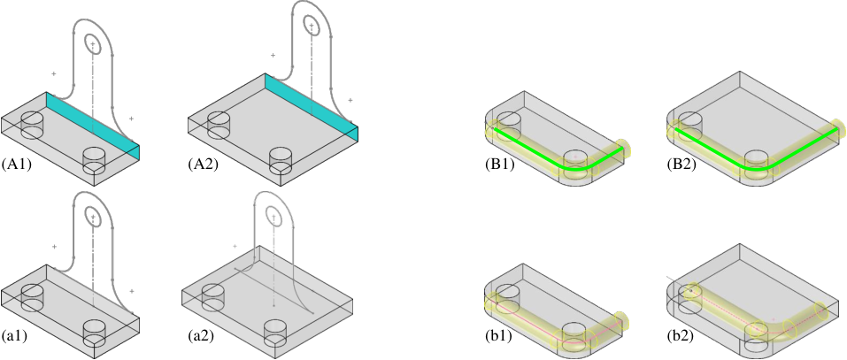
Geometry reference involves selecting specific existing faces, edges, or vertices for a modeling operation. For example, creating a sketch requires selecting its support plane. Incorrect references may produce the intended initial shape but lead to unintended updates after parameter edits (Figure 2).
Early methods predict sketch-plane origins and axis directions directly Wu et al. [2021]. Later approaches add limited dependencies, such as referencing a face through the sketch edge that generates it Yuan et al. [2024], Li et al. [2026b], CadQuery Developers [2026]. Richer operations require more general geometry references. Engineers select these entities interactively; an AI system needs a representation that makes them identifiable to the VLM.
3.2 Understanding Sketch-Plane Local Coordinate Systems
Sketch primitives are defined in the sketch plane’s two-dimensional local coordinate system. The CAD kernel assigns the origin and axes. Identical coordinates on different planes can therefore produce very different spatial positions (Figure 3).

Many existing methods primarily use sketch planes parallel to the XOY, YOZ, or XOZ planes, with local axes aligned or oppositely with the global axes Wu et al. [2021], Wang et al. [2025], Yuan et al. [2024]. SkexGen reports that such planes account for over 99% of DeepCAD sketches Xu et al. [2022], reducing the need to handle more varied sketch-plane orientations in that dataset. Nevertheless, inclined planes occur in engineering models. The challenge is to expose their coordinates through a clear visual interface or map predicted positions into sketch local coordinate system.
3.3 Sketch Constraints with Projected External Geometry
Projected geometry constants link sketch primitives to existing edges or vertices. For example, a circle center can coincide with a projected vertex. This association lets the sketch update when upstream dimensions change (Figure 4).

Several methods output sketch primitive definitions directly Wu et al. [2021], Xu et al. [2022], Yuan et al. [2024], Li et al. [2026b]. Pointer-CAD supports snapping to existing edges Qi et al. [2026]; maintaining such an association during later edits additionally requires a persistent constraint. Establishing constraints to projected external geometry requires identifying both the source geometry and its projection on the sketch plane.
4 Method
Vision2CAD constructs a parametric CAD model from an input image by combining VLM predictions with deterministic CAD kernel operations. Its interfaces support entity referencing, sketch coordinate conversion, and external sketch constraints within the supported modeling operations. The overall workflow is shown in Figure 5.

4.1 Stage 1: Operation Selection
4.1.1 Registration
We render a depth image from . Relative linear depth is shown from white (near) to black (far). Magenta solid and dashed lines mark visible and occluded edges. The default PNP view has direction and up vector .
Registration adjusts the camera scale and translation to align with . The resulting camera , places existing geometry at the corresponding target location, helping identify regions to be modeled in Stage 1 (Figure 6 left).

Using , we render the tag image and export the geometry table . They expose the current geometry together for reference selection (Figure 7).

4.1.2 Retrieval-Augmented Generation (RAG)
We use the current depth image and target image to retrieve modeling examples . The retrieved pseudo-previews provide visual precedents for the next operation (Figure 8).

Similarity to retrieval record is a weighted combination of cosine similarities:
Here, and compare current geometry and target shape, respectively. The weight balances the two. is the normalized [CLS] token from a frozen DINOv3 ViT-B/16 backbone Siméoni et al. [2025].
4.1.3 VLM Invocation
The Stage 1 VLM input–output mapping is
The prompt explains the inputs and requests the next command type, references, and parameters. The output follows the JSON schema in Table 1.
| Field | Description |
|---|---|
| TYPE | Type of the next FreeCAD operation, or the termination token END. |
| REQUIRE_SKETCH | Whether Stage 2 must generate a new sketch. Stage 2 is skipped if this value is false. |
| SKETCH_REF | ID of the sketch plane for a new sketch. |
| SKETCH_HINT | Brief description of the intended shape and location, guiding Stage 2. |
| OTHER_REFERENCE | Other reference IDs: directions, revolution axes, sweep paths, loft sections, fillet/chamfer edges, and construction-plane source faces. |
| PARAMETER_HINT | Approximate depth, angle, offset, fillet radius, or chamfer distance, relative to the view scale in . |
| DIR_HINT | Qualitative direction in the current view, such as extrusion along the positive or negative side of the sketch plane. |
4.2 Stage 2: Sketch Generation
4.2.1 VLM Invocation
Before invoking the VLM, Stage 2 orients the camera normal to the selected sketch plane. The pseudo-bounding sphere (constructed under the registered Stage 1 camera) determines the translation and scale to help keep the intended sketch within the viewport (Figure 6). The system then renders the tag image and exports the geometry table from this sketch view.
The Stage 2 VLM input–output mapping is
The prompt requests one or more closed profiles in the view coordinates of . The CAD kernel converts these coordinates into the sketch plane’s actual local coordinates. Projected edge samples in guide primitive placement. For example, a sketch line can use the projected endpoints of an existing edge to align with it. The output defines primitives in JSON: a line uses two endpoints; an arc uses start, intermediate, and end points. A circle uses four ordered points on its circumference.
4.2.2 Sketch Constraint Generation
Constraints are added in three stages: links to projected external geometry, relationships among sketch primitives, and dimensions. Candidate relationships are detected from the predicted geometry using tolerance tests.
(1) Constraints to projected geometry. Existing edges are imported as external sketch geometry using their source IDs and projected coordinates. We apply constraints in the following order: (i) collinearity between a sketch line and a projected straight edge; (ii) coincidence of a sketch line or arc endpoint with a projected edge endpoint or the projected center of an external circle or arc; and (iii) point-on-object constraints that place a sketch line or arc endpoint on a projected edge. These constraints link the sketch to the source geometry.
(2) Constraints among sketch primitives. We next apply endpoint coincidence, horizontal and vertical line constraints, tangency involving circles or arcs, equal line lengths, equal arc radii, and point symmetry, in that order. Each candidate is tested using the positional, angular, length, or radius adjustment needed to satisfy the relationship.
For symmetric constraint, we project the outer loop of the sketch face. If the projected outline is symmetric about both its horizontal and vertical midlines, their intersection and the two midlines define the reference center and symmetry axes. Otherwise, we use the sketch origin and its axes. The same fallback applies when no supporting face is available. Symmetry constraints are detected on primitive endpoints and circle or arc centers.
(3) dimensional constraints. Dimensional constraints specify line lengths, circle or arc radii, and key-point offsets from the reference center measured along the reference axes. Lengths and radii are measured after geometric constraints have been applied.
FreeCAD solves the sketch after each constraint is added. Candidates that overconstrain the sketch are reverted, and constraint addition stops when no degrees of freedom remain.
4.3 Stage 3: Execution Verification
FreeCAD executes the command defined by and, when required, to render a modeling preview (Figure 9). The Stage 3 VLM input–output mapping is
The prompt asks whether the candidate creates a missing target structure or a useful intermediate feature. The JSON output contains an acceptance decision and a brief acceptance justification or detailed rejection reasons. Accepted commands update to . Rejection reasons are added to the context before restarting Stage 1.


5 Experiments
5.1 Geometry Explicit Reference Dataset (GERD)
GERD contains 2,700 publicly available Onshape parts, split into 2,500 training, 100 validation, and 100 test samples. It covers extrusion, revolution, sweep, loft, chamfer, fillet, and create construction plane. Each modeling step records the command, resulting geometry, and available entity IDs (Figure 10). To the best of our knowledge, GERD is the first dataset to align these records across the full Body, Face, Edge, and Vertex hierarchy at every step.
GERD-RET uses the GERD training split for modeling example retrieval (Figure 8). GERD-EVL is derived from GERD for image-to-CAD code generation and inherits its training, validation, and test splits. Each sample is . Here, is the completed-part image and is its cadfs program Pyatov et al. [2026]. The two STEP files store the original geometry and the result after increasing all extrusion depths by .
GERD also supports the derivation of datasets with different viewpoints, rendering modalities, and supervision targets. Potential tasks include next-command prediction, face/edge/vertex selection, B-Rep encoding, and validating references across modeling steps. GERD thus serves both as a data source for this work and as a reusable intermediate representation for stepwise parametric CAD modeling.
5.2 Implementation Details
All stages use gpt-5.6-sol as VLM, with at most two failed verification attempts in Stage 3. Stage 1 retrieves up to three examples with . We use FreeCAD 1.1 and render images at pixels. Generation stops at END or 25 modeling steps and returns the current document, which may represent an incomplete model.
Training-based baselines are trained on the GERD-EVL training split to generate cadfs code Pyatov et al. [2026]. Other baselines generate FreeCAD or CadQuery code and use the gpt-5.6-sol VLM unless specified otherwise. Evaluation on DeepCAD uses the 100-part CADCoder-test100 subset because evaluating the full test set is computationally costly Doris et al. [2025].
5.3 Evaluation Metrics
We report compilation success rate (CR) (For Vision2CAD, the generated FreeCAD document is marked as compiled successfully if it is non-empty and reports no errors), mean intersection over union (mIoU), Chamfer distance (CD), Hausdorff distance (HD), and 95th-percentile Hausdorff distance (HD95). HD95 excludes the largest of pointwise distances. Geometric metrics are computed only for samples counted as successful under the CR criterion. These metrics describe the quality of the returned geometry and must be interpreted alongside CR.
We evaluate static reconstruction and a specific parameter-editing protocol. For editing, all additive and subtractive extrusion depths are simultaneously multiplied by in each generated program and its ground-truth counterpart. We then recompute CR and the geometric metrics against the edited ground truth.
The motivation for conducting parameter-editing experiment is as follows: a parametric CAD part can often be constructed through multiple valid feature histories, with different feature decompositions, reference entities, and sketch constraints producing the same final geometry. Consequently, directly measuring reference or constraint accuracy against a single ground-truth construction history is not generally meaningful. Nevertheless, part of the modeling intent is observable from the target image through geometric relationships. For example, the inner and outer cylindrical surfaces of an annular feature imply that the corresponding sketch circles should typically be concentric. To evaluate whether such image-supported design intent is captured by the generated parametric dependencies, we perturb the extrusion depth by and examine how the model geometry responds to the parameter change. A model whose references and constraints correctly encode these relationships is expected to preserve the corresponding geometric dependencies during editing. Therefore, this experiment provides an indirect assessment of whether the reconstructed model captures design intent through its parametric dependency structure. Although a single extrusion-depth perturbation cannot fully characterize model editability or complete design-intent preservation, it evaluates an important aspect of parametric behavior that cannot be measured static model reconstruction.
5.4 Experimental Results
Static reconstruction. Vision2CAD returns non-empty documents with no reported errors for all test cases ( CR) and achieves the best reported geometric metrics on both datasets (Tables 2 and 3). On GERD-EVL, mIoU improves by and CD decreases by relative to the strongest baseline for each metric. These comparisons are based on each method’s outputs that satisfy both CR conditions: CAD-Coder’s mIoU of covers only 18 of the 100 test parts, whereas Vision2CAD’s scores cover all 100.
DeepCAD mainly contains regular sketch–extrusion sequences. Most baselines reach at least CR, so the evaluated subsets differ less in size than on GERD-EVL. Vision2CAD improves mIoU by and reduces CD by relative to the strongest baseline for each metric. These results indicate improved geometric reconstruction on the evaluated outputs.
| Category | Method | CR (%) | mIoU | CD | HD | HD95 |
|---|---|---|---|---|---|---|
| Trained models | ReCAD-SFT | 43.0 | 0.2931 | 0.1103 | 0.2004 | 0.1430 |
| ReCAD-GRPO | 44.0 | 0.2980 | 0.0955 | 0.1912 | 0.1211 | |
| CAD-Coder | 18.0 | 0.4261 | 0.0832 | 0.1596 | 0.1098 | |
| Training-free agents | CADCodeVerify | 89.0 | 0.3989 | 0.1017 | 0.1975 | 0.1297 |
| CAD-Assistant | 100.0 | 0.4038 | 0.0721 | 0.1558 | 0.0909 | |
| Direct generation | gpt-5.6-sol | 84.0 | 0.3920 | 0.0964 | 0.1822 | 0.1139 |
| deepseek-v4-pro | 75.0 | 0.3570 | 0.0922 | 0.1741 | 0.1108 | |
| Ours | Vision2CAD | 100.0 | 0.4733 | 0.0596 | 0.1125 | 0.0663 |
| Category | Method | CR (%) | mIoU | CD | HD | HD95 |
|---|---|---|---|---|---|---|
| Trained models | ReCAD-SFT | 98.0 | 0.6421 | 0.0743 | 0.1289 | 0.0889 |
| ReCAD-GRPO | 99.0 | 0.6051 | 0.0762 | 0.1361 | 0.0891 | |
| CAD-Coder | 97.0 | 0.6619 | 0.0637 | 0.1270 | 0.0847 | |
| Training-free agents | CADCodeVerify | 99.0 | 0.6038 | 0.0586 | 0.1065 | 0.0676 |
| CAD-Assistant | 100.0 | 0.6170 | 0.0631 | 0.1125 | 0.0743 | |
| Direct generation | gpt-5.6-sol | 98.0 | 0.5988 | 0.0550 | 0.0949 | 0.0630 |
| deepseek-v4-pro | 96.0 | 0.4636 | 0.0951 | 0.1560 | 0.1115 | |
| Ours | Vision2CAD | 100.0 | 0.6987 | 0.0320 | 0.0551 | 0.0332 |
Parameter editing. Vision2CAD retains CR and the best reported geometric metrics after the uniform extrusion-depth increase (Tables 4 and 5). Relative to the strongest baseline for each metric, mIoU improves by on GERD-EVL and on DeepCAD. CD decreases by and , respectively. All Vision2CAD outputs are more closely matches the edited ground truth according to the reported scores.
| Category | Method | CR (%) | mIoU | CD | HD | HD95 |
|---|---|---|---|---|---|---|
| Trained models | ReCAD-SFT | 43.0 | 0.2961 | 0.1096 | 0.1972 | 0.1406 |
| ReCAD-GRPO | 44.0 | 0.2957 | 0.0969 | 0.1925 | 0.1203 | |
| CAD-Coder | 15.0 | 0.4458 | 0.0883 | 0.1662 | 0.1176 | |
| Training-free agents | CADCodeVerify | 89.0 | 0.3967 | 0.1027 | 0.1984 | 0.1311 |
| CAD-Assistant | 98.0 | 0.4055 | 0.0759 | 0.1608 | 0.0937 | |
| Direct generation | gpt-5.6-sol | 84.0 | 0.3906 | 0.0977 | 0.1826 | 0.1160 |
| deepseek-v4-pro | 75.0 | 0.3620 | 0.0930 | 0.1755 | 0.1115 | |
| Ours | Vision2CAD | 100.0 | 0.4770 | 0.0606 | 0.1149 | 0.0687 |
| Category | Method | CR (%) | mIoU | CD | HD | HD95 |
|---|---|---|---|---|---|---|
| Trained models | ReCAD-SFT | 98.0 | 0.6346 | 0.0739 | 0.1276 | 0.0873 |
| ReCAD-GRPO | 99.0 | 0.6035 | 0.0771 | 0.1360 | 0.0900 | |
| CAD-Coder | 97.0 | 0.6595 | 0.0643 | 0.1276 | 0.0845 | |
| Training-free agents | CADCodeVerify | 99.0 | 0.5950 | 0.0623 | 0.1096 | 0.0707 |
| CAD-Assistant | 100.0 | 0.5950 | 0.0676 | 0.1159 | 0.0769 | |
| Direct generation | gpt-5.6-sol | 98.0 | 0.5860 | 0.0591 | 0.0979 | 0.0667 |
| deepseek-v4-pro | 96.0 | 0.4747 | 0.0954 | 0.1548 | 0.1120 | |
| Ours | Vision2CAD | 100.0 | 0.6875 | 0.0343 | 0.0581 | 0.0362 |
Qualitative results. In the GERD-EVL examples in Figure 11, baseline outputs miss holes, supports, or curved profiles, and some methods return no geometry. Vision2CAD recovers these structures more consistently in the illustrated cases. Most methods recover the basic shapes of the DeepCAD examples, while Vision2CAD better matches their local contours and feature positions.

5.5 Ablation Studies
We evaluate six ablations on GERD-EVL under the same static and editing protocols.
- 1.
w/o EGR (explicit geometry referencing): Stage 1 removes edge ID labels and leader lines from and omits . CadQuery selectors replace explicit entity IDs (e.g., >Z selects the highest face and |Z selects edges parallel to ).
- 2.
w/o LCB (local-coordinate bridge): Stage 2 omits the bridge from view coordinates to sketch local coordinates. The VLM must instead predict sketch primitive coordinates directly in the sketch plane’s actual local coordinate system.
- 3.
w/o PGR (projected geometry referencing): Stage 2 removes edge samples from and disables sketch constraints to projected external geometry.
- 4.
w/o Reg (registration): Stage 1 disables image registration and the associated sphere . Stage 2 removes the restriction on predicted sketch coordinates.
- 5.
w/o RAG (retrieval): Stage 1 does not retrieve similar modeling examples from GERD-RET. The VLM predicts the next command using only the current model state and target image.
- 6.
w/o EVf (execution verification): Remove Stage 3 (the preview-based verification). Modeling commands generated by Stages 1 and 2 are committed without visual verification.
| Configuration | CR (%) | mIoU | CD | HD | HD95 |
|---|---|---|---|---|---|
| Full | 100.0 | 0.4733 | 0.0596 | 0.1125 | 0.0663 |
| w/o EGR | 100.0 | 0.4187 | 0.0891 | 0.1852 | 0.1143 |
| w/o LCB | 100.0 | 0.4332 | 0.0852 | 0.1726 | 0.1045 |
| w/o PGR | 100.0 | 0.4658 | 0.0639 | 0.1133 | 0.0938 |
| w/o Reg | 100.0 | 0.4589 | 0.0623 | 0.1374 | 0.0889 |
| w/o RAG | 100.0 | 0.4522 | 0.0649 | 0.1241 | 0.0785 |
| w/o EVf | 100.0 | 0.4478 | 0.0724 | 0.1451 | 0.0924 |
| Configuration | CR (%) | mIoU | CD | HD | HD95 |
|---|---|---|---|---|---|
| Full | 100.0 | 0.4770 | 0.0606 | 0.1149 | 0.0687 |
| w/o EGR | 98.0 | 0.4128 | 0.0875 | 0.1590 | 0.0905 |
| w/o LCB | 90.0 | 0.4139 | 0.1035 | 0.1826 | 0.1380 |
| w/o PGR | 89 | 0.4263 | 0.0882 | 0.1487 | 0.1029 |
| w/o Reg | 96.0 | 0.4483 | 0.0817 | 0.1573 | 0.1024 |
| w/o RAG | 98.0 | 0.4585 | 0.0758 | 0.1332 | 0.0827 |
| w/o EVf | 95.0 | 0.4367 | 0.0810 | 0.1516 | 0.1029 |
All configurations achieve CR in static reconstruction, but the full system gives the best geometric scores (Table 6). Editing exposes larger differences in execution success (Table 7).
Removing explicit geometry referencing (EGR) causes the largest static mIoU drop, from to . After editing, CR falls to and mIoU to , the lowest among the ablations. This supports the importance of accurate entity selection throughout the feature sequence.
Without the local-coordinate bridge (LCB), static mIoU falls to and editing CR to . Sketch coordinate errors thus affect both initial geometry and later updates. Deterministic coordinate conversion reduces this source of error.
Projected geometry referencing (PGR) has a modest static effect: mIoU falls only to . After editing, however, CR falls to and mIoU to . Predicting nearby sketch coordinates can reproduce an initial profile, but cannot replace persistent references to source geometry. PGR provides those references and supports subsequent parameter propagation.
Registration, RAG, and execution verification also improve geometric scores. Removing them reduces editing CR to , , and , respectively. Their contributions complement the reference mechanisms through visual alignment, modeling examples, and rejection of incorrect operations.
6 Conclusions
We presented Vision2CAD, a visual agent harness for generating native parametric CAD models from single images. It combines explicit entity references, a local-coordinate bridge, and sketch constraints to projected external geometry. These mechanisms establish feature dependencies within the supported modeling operations and constraint types. GERD provides aligned commands, geometric states, and entity IDs for research on these dependencies.
Vision2CAD achieves the best geometric accuracy among the evaluated methods on GERD-EVL and the DeepCAD test subset. It also retains a compilation success rate after extrude depths increase by . Ablation results highlight the role of explicit dependencies in preserving editability, especially when static geometry alone appears accurate.
The system remains limited by its single target view and dense edge labels on complex parts. It does not yet support references to entities internal to sketches or operations such as linear and circular patterns. Future work will extend these capabilities and explore multiple views, active viewpoint planning, and adaptive entity visualization.
CRediT authorship contribution statement
First Author: Conceptualization, Methodology, Software, Validation, Writing – original draft. Second Author: Supervision, Writing – review and editing.
Declaration of competing interest
The authors declare that they have no known competing financial interests or personal relationships that could have appeared to influence the work reported in this paper.
Funding
This research did not receive any specific grant from funding agencies in the public, commercial, or not-for-profit sectors.
Data availability
The data and code supporting the findings of this study will be made available at [repository and persistent identifier] upon publication.
References
- CADSmith: multi-agent CAD generation with programmatic geometric validation. arXiv preprint arXiv:2603.26512. External Links: 2603.26512, Link Cited by: §1, §2.3.
- Selectors reference. Note: https://cadquery.readthedocs.io/en/latest/selectors.htmlCadQuery Documentation, accessed August 18, 2026 Cited by: §2.2, §3.1.
- CADCrafter: generating computer-aided design models from unconstrained images. In Proceedings of the IEEE/CVF Conference on Computer Vision and Pattern Recognition (CVPR), pp. 11073–11082. External Links: Link Cited by: §1, §2.1.
- Img2CAD: conditioned 3-d CAD model generation from single image with structured visual geometry. IEEE Transactions on Industrial Informatics 21 (11), pp. 8539–8549. External Links: Document, Link Cited by: §1, §1, §2.1.
- On the role of generating textual description for design intent communication in feature-based 3D collaborative design. Advanced Engineering Informatics 39, pp. 331–346. External Links: Document, Link Cited by: §1.
- CAD-Coder: an open-source vision-language model for computer-aided design code generation. arXiv preprint arXiv:2505.14646. External Links: 2505.14646, Link Cited by: §1, §2.2, §5.2, Table 3, Table 3, Table 5, Table 5.
- Ortho2CAD: 3d CAD generation from orthographic drawings using vision language models. arXiv preprint arXiv:2607.08891. External Links: 2607.08891, Link Cited by: §1, §2.2.
- Text2CAD: generating sequential CAD designs from beginner-to-expert level text prompts. In Advances in Neural Information Processing Systems, Vol. 37, pp. 7552–7579. External Links: Document, Link Cited by: §1, §2.1.
- ReCAD: reinforcement learning enhanced parametric CAD model generation with vision-language models. In Proceedings of the AAAI Conference on Artificial Intelligence, Vol. 40, pp. 6190–6198. External Links: Document, Link Cited by: §2.2.
- Seek-CAD: a self-refined generative modeling for 3d parametric CAD using local inference via DeepSeek. In International Conference on Learning Representations (ICLR), External Links: Link Cited by: §1, §2.3, §3.1, §3.3.
- LLMs driven fusion AI-AD system for mechanical design: from understanding to generation. Advanced Engineering Informatics 68, pp. 103745. External Links: Document, Link Cited by: §2.3.
- Draw step by step: reconstructing CAD construction sequences from point clouds via multimodal diffusion. In Proceedings of the IEEE/CVF Conference on Computer Vision and Pattern Recognition (CVPR), pp. 27154–27163. External Links: Link Cited by: §1, §2.1.
- CAD-Assistant: tool-augmented VLLMs as generic CAD task solvers. In Proceedings of the IEEE/CVF International Conference on Computer Vision (ICCV), pp. 7284–7294. External Links: Link Cited by: §1, §2.3.
- CADFS: a big CAD program dataset and framework for computer-aided design with large language models. In Proceedings of the IEEE/CVF Conference on Computer Vision and Pattern Recognition (CVPR), External Links: 2605.01925, Link Cited by: §5.1, §5.2.
- Pointer-CAD: unifying B-Rep and command sequences via pointer-based edges & faces selection. In Proceedings of the IEEE/CVF Conference on Computer Vision and Pattern Recognition (CVPR), pp. 17377–17387. External Links: Link Cited by: §1, §3.3.
- CAD-Recode: reverse engineering CAD code from point clouds. In Proceedings of the IEEE/CVF International Conference on Computer Vision (ICCV), pp. 9801–9811. External Links: Link Cited by: §1, §2.2.
- DINOv3. External Links: 2508.10104, Link Cited by: §4.1.2.
- CAD-GPT: synthesising CAD construction sequence with spatial reasoning-enhanced multimodal LLMs. In Proceedings of the AAAI Conference on Artificial Intelligence, Vol. 39, pp. 7880–7888. External Links: Document, Link Cited by: §3.2.
- DeepCAD: a deep generative network for computer-aided design models. In Proceedings of the IEEE/CVF International Conference on Computer Vision (ICCV), pp. 6772–6782. External Links: Link Cited by: §1, §2.1, §3.1, §3.2, §3.3.
- SkexGen: autoregressive generation of CAD construction sequences with disentangled codebooks. In Proceedings of the 39th International Conference on Machine Learning, pp. 24698–24724. External Links: Link Cited by: §3.2, §3.3.
- Parametric feature constraint modeling and mapping in product development. Advanced Engineering Informatics 26 (3), pp. 539–552. External Links: Document, Link Cited by: §1.
- CAD-Refiner: a unified framework for CAD generation and iterative editing. In Proceedings of the IEEE/CVF Conference on Computer Vision and Pattern Recognition (CVPR), pp. 3244–3253. External Links: Link Cited by: §1.
- OpenECAD: an efficient visual language model for editable 3d-cad design. Computers & Graphics 124, pp. 104048. Cited by: §3.1, §3.2, §3.3.