Topology optimisation and simulated state reconstruction for self-sensing piezoresistive grippers
Abstract
We consider the computational design of a self-sensing robotic gripper that has the potential to reduce reliance on traditional external sensors. We computationally investigate the potential of a novel sensing method that exploits the coupled electromechanical properties of piezoresistive materials to enable mechanical perception using sparse electrical measurements. In this theoretical proof-of-concept, we show that under the idealised assumptions of linear constitutive relationships and quasi-static gripper operation, it is possible to reconstruct simple contact shapes and gripper displacement fields using a small number of simulated electrical measurements, suggesting the potential of the proposed sensing technique. We use topology optimisation to promote the quality of displacement state recovery by adding an electrical performance objective to the mechanical compliance requirement of the gripper. Using the proposed reconstruction technique, we showcase the improved reconstruction ability of an electrically optimised gripper design through an increased robustness to noisy synthetic measurements compared to a gripper designed with only a mechanical objective in the topology optimisation problem. In the future, detailed inclusion of non-linear effects and experimental realisation of this theoretical proof-of-concept may help remove the constraints of traditional sensors for robotic handling, potentially facilitating sensing in settings where current sensing systems are impractical.
keywords
grippers, inverse problems, multi-physics, topology optimisation, self-sensing, piezoresistive materials1 Introduction
Automating tasks traditionally requiring manual labour is a cornerstone of modern industrial practice. Robotic systems have been developed to address a subset of these tasks that involve interaction with the physical environment. In particular, for applications requiring the handling of complex, delicate, and deformable objects, soft robotic grippers are especially well suited (Shintake et al., 2018; Kim et al., 2013). This follows from their inherent material compliance, enabling them to conform to the geometries of objects and apply gentle, evenly distributed forces (Shintake et al., 2018; Rus and Tolley, 2015).
During gripper operation, measurements of contact forces and internal stresses are essential for ensuring effective grasps and preventing structural failure (Hegde et al., 2023). A structural model of a gripper can be developed to predict these quantities based on known boundary conditions. In practice, however, when the gripper interacts with an unknown object the boundary conditions at the contact interface are not known. A sensing mechanism is therefore required to obtain this boundary information. Rigid sensors in the contact zone compromise the compliance of the gripper, involve complex wiring and are prone to damage (Van Duong and Ho, 2021; Shimonomura, 2019). An alternative is to obtain missing information through a complex 3D vision system, although this may involve a cumbersome setup and be prone to occlusion (Greenland et al., 2025; Zhan et al., 2025; Van Duong and Ho, 2021; Liu et al., 2024). We instead consider the possibility of obtaining such information by utilising a piezoresistive material for the gripper and exploiting the piezoresistive effect, to facilitate sensing in cases where a vision system is not feasible. The piezoresistive effect describes the change in electrical resistivity of a material when subjected to mechanical stress (Smith, 1954). Current systems that integrate piezoresistive materials into grippers provide a low-dimensional electrical signal that can be used only to obtain low-order information, such as contact detection or object identification (Stano et al., 2022; Shih et al., 2019; Georgopoulou et al., 2021; Georgopoulou and Clemens, 2022). In contrast, we propose a new approach that enables recovery of an approximation of the entire displacement field and therefore the internal stresses and contact forces of the gripper based on electrical readings at a sparse set of convenient measurement locations.
To the best of our knowledge, no prior work has attempted to recover the full displacement field of a gripper from sparse electrical measurements. We consider this computational proof-of-concept as a first step investigating the potential of piezoresistive materials to provide self-sensing capability for robotic grippers. As such, we consider the simplest setting that still allows us to investigate the potential of the sensing method. Specifically, we assume that: the piezoresistive material lies at the relatively stiff end of the soft-material spectrum, for example, it is manufactured using a thermoplastic filament; the gripper does not undergo large deformations; and the gripper operates quasi-statically. These assumptions restrict the direct applicability of the models used in this work to a limited class of gripper applications, but they provide a foundation for future work addressing more general nonlinear behaviour. We further note that experimental validation of the piezoresistive electrical response and sensing methodology is outside of the scope of the current work. Recent works involving physical experiments on the piezoresistive response of printed materials that motivated this work can be found in the literature Georgopoulou and Clemens (2022); Georgopoulou et al. (2021); Georgopoulou et al. (2020); Riddervold et al. (2024). We note that the constitutive behaviour of some of these filaments is linear in the reported experiments, which is consistent with the assumptions made in this work.
For displacement-field recoverability, the piezoresistive response must be measurable and information-rich. To provide this, we employ a topology optimisation approach to design the gripper’s geometry, simultaneously maximising the piezoresistive response and mechanical performance to ensure reliable information recovery and high-quality grasps. The mechanical performance of a gripper can be accounted for by a variety of different objective functions in the topology optimisation problem, depending on the application. A common approach is to consider the gripper as a compliant mechanism and to maximise the output displacement at the gripper tip for a given input force. This can either be done directly by maximising the output displacement (Sun et al., 2022; Pinskier et al., 2024; Xie et al., 2024), or by maximising the mutual strain energy (Liu et al., 2018; Liu et al., 2022). These objectives are considered to improve the gripper’s ability to close around objects (Pinskier et al., 2024). An alterative objective is to measure how close the deformation of the gripper is to a target deformation, which can be used to design grippers that achieve specific motion (Chen et al., 2021; Liu et al., 2021). Depending on the formulation and application, a minimisation of overall strain energy may also be considered as an additional mechanical objective, which can either act as a regularisation term for optimisation or be an important consideration when overall stiffness is desirable (Liu et al., 2018; Pinskier et al., 2024). Topology optimisation approaches for more general compliant mechanisms are also extensively studied in the literature, with a variety of combinations of compliance and stiffness objectives (Zhu et al., 2020). Other works combine the compliance objective with additional objectives and constraints, such as for the stress (De Leon et al., 2015) or fundamental frequency (Wang et al., 2024). To date, however, no work has combined a compliance objective with a piezoresistive response maximisation. Work in topology optimisation that involves piezoresistive materials generally focuses on a single sensor design (Zhu et al., 2016; Zhuang et al., 2023; Guo et al., 2024; Rubio et al., 2007; Giusti et al., 2014; Mello et al., 2012). Recently, the design of structures with self-sensing as an additional characteristic have been investigated by Seifert et al. (2019b); Seifert et al. (2019a), who use a functionally graded material to balance stiffness and sensing objectives. Consistent with the previous works focused on sensor design, we seek to maximise the piezoresistive response to improve the signal-to-noise ratio of the electrical measurements. For the first time we combine this with a compliant mechanism objective. Moreover, whereas existing designs target a single overall electrical response, we instead maximise signals across multiple electrode source-sink patterns and measurement locations.
Prior formulations for piezoresistive topology optimisation use density-based approaches that introduce interpolated materials into the topology optimisation problem (Zhu et al., 2016; Zhuang et al., 2023; Guo et al., 2024; Rubio et al., 2007; Giusti et al., 2014; Mello et al., 2012; Seifert et al., 2019b; Seifert et al., 2019a). Although convenient, these topology optimisation methods may induce non-physical features when considering the piezoresistive topology optimisation problem due to the presence of the interpolated material. To avoid this, we adopt an unfitted topology optimisation approach that eliminates interpolated materials altogether. Without re-meshing, unfitted finite element methods (Badia et al., 2018; Burman et al., 2015) integrate the governing equations over the physical domain only. These methods are advantageous for topology optimisation in multi-physics contexts where the introduction of artificial densities are undesirable (Jenkins and Maute, 2015; Villanueva and Maute, 2017). Unfitted topology optimisation has been successfully applied to topology optimisation problems in various multi-physics contexts, including fluid-structure interaction (Jenkins and Maute, 2015) and fluid-transport (Villanueva and Maute, 2017). To date, however, these methods have not been considered for electromechanical formulations such as the piezoresistive problem. In this work, we formulate an unfitted framework for the piezoresistive problem with a mixed mechanical and electrical objective that eliminates the introduction of artificial interpolated materials that can lead to non-physical features when considering the multi-physics formulation.
In the second part of this work, we propose a method for reconstructing unknown contact geometries based on sparse electrical measurements taken during gripper operation. In this work, we consider simulated electrical measurements obtained when grasping a target object. Discarding all information about the target object except for these measurements, we attempt to reconstruct the shape and location of the contact object by solving an inverse problem. With a reconstruction of a contact geometry, we can determine an approximation of the entire displacement field of the gripper by solving the forward problem. A related problem that has been extensively studied in the medical imaging literature is the classical problem of eit (eit) that involves the reconstruction of unknown conductivity fields from electrical measurements (Youssef Baby et al., 2024). In recent decades, numerous studies have introduced force sensor skins based on tomographic reconstruction principles, allowing the use of soft materials to recover force locations without wiring in the contact region (Dai and Thostenson, 2019; Nagakubo et al., 2007; Alirezaei et al., 2007; Wu et al., 2022; Soleimani and Friedrich, 2022).
The sensor skin problem involves recovering the location of an unknown force along a surface. In this work, we consider a related but distinct problem: recovering the location and shape of an unknown contact object. The difference is that we require a contact formulation, i.e., we need to recover how deformed the gripper is when it comes into contact with the object, as well as where along the gripper’s surface the contact occurs. To the best of our knowledge, there is no existing work that solves this specific inverse problem by coupling a contact mechanics model with an electrical forward model to reconstruct unknown contact geometries from electrical measurements. The closest examples of coupling mechanics into an electrical inverse problem are found in the self-sensing composites literature. Tallman et al. (2017) invert electrical impedance tomography conductivity data through an analytical piezoresistivity model to recover the displacement field of a specimen under known loading conditions. Conversely, Hassan and Tallman (2023) reconstruct an a priori unknown damage geometry, such as through-holes and delaminations, from electrical impedance tomography data, but do so using a purely electrical forward model without coupling any mechanical equilibrium equation. We consider a level set-based representation to be a natural choice here for parametrisation of the contact shape, and consider this level-set based reconstruction method as an extension of the current tomographic reconstruction literature to problems involving contact.
The article is organised as follows. In Section 2 we introduce the governing equations of the problem and in Section 3 we present the numerical discretisation. In Section 4 we detail the proposed topology optimisation framework and obtain a new gripper design considering both electrical and mechanical objectives. In Section 5 we introduce the inverse framework for reconstructing unknown contact geometries and gripper displacement fields and demonstrate the enhanced performance of the new gripper design using synthetic data. Finally, Section 6 discusses limitations of the theoretical proof-of-concept presented in the paper, and concluding remarks are given in 7.


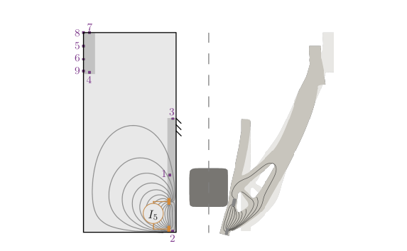
2 Model equations
In this section we describe the continuum model for the coupled mechanical and electrical problems for a piezoresistive gripper. The design domain adopted in this work is based on the one introduced by Liu et al. (2018) and is shown in Figure 1. The left hand side of the symmetrical problem is considered, with a gripper visualised on the right to aid in interpretation of the diagram. We define as the domain occupied by the solid gripper material. This is composed of the passive domain and a portion of the design domain depending on the design. A formal definition for is given in Section 3. Assuming linear elasticity and a conservation of charge, and noting that the piezoresistive effect couples the displacement and electric fields through a displacement-dependent conductivity (Smith, 1954), we obtain the following strong form of the governing equations for the interior of the domain:
| (1) |
where is the stress tensor, is the small-strain symmetric tensor, and are the Lamé parameters given by and and and are the Young’s modulus and Poisson’s ratio, respectively, considering plane strain conditions.
The displacement-dependent conductivity tensor for the 2D problem is defined as:
| (2) |
with components approximated through the linear constitutive relation used by Giusti et al. (2014):
| (3) | ||||
where is the base conductivity of the material under zero displacement and and are the piezoresistivity coefficients. A homogeneous Dirichlet condition is prescribed on the displacement:
| (4) |
and traction boundary conditions are applied on the remainder of the boundary:
| (5) |
where is the outward unit normal vector to the boundary, is the forcing term with a magnitude applied at on the input port as shown in Figure 1 and is the stiffness of the actuator at the input port. The condition on the contact surface follows a frictionless penalty method (Yastrebov, 2013, Eq. 4.73,), where is a small parameter, is the positive part function and is the gap function, defined as the distance between the gripper and the contact object. Using this method, a large normal reaction force is applied whenever the gripper intrudes into the object, i.e. when . The remainder of the boundary is traction-free.
Along with the electrodes used to measure the electrical potential, we also must include electrodes to apply current to the system. This is done by applying Dirichlet conditions on the potential at some source-sink electrodes. We make clear here that these additional electrodes, which act as sink and source boundary conditions for the potential, are distinct from the measurement electrodes that are used only to measure the potential and do not affect the governing equations. We select a few different locations for these source-sink electrodes and solve the coupled problem for each of them. Using multiple current source-sink patterns increases the amount of independent information obtained, improving reconstruction accuracy (Isaacson, 1986). We adopt adjacent source-sink patterns, common in eit (Russo et al., 2017) which involves selecting sets of two adjacent electrodes as the source and sink electrodes. The source-sink patterns for are seen in Figure 2 and involve the prescription of the following Dirichlet conditions on the potential:
| (6) |
where . An example of one such current source-sink pattern is shown in Figure 3. On the remainder of the boundary, the electrical insulation condition is applied:
| (7) |
The values of the physical constants introduced in this section are given in Table 1. The material is assumed to have the Young’s modulus of a relatively stiff thermoplastic (as per the gripper printed using piezoresistive filament for the experiment in Section 6). As per the constitutive equations above, the material is assumed to behave linearly elastically and geometric nonlinearities are ignored. The validity of both of these assumptions is analysed in more detail in Section 6. Quasi-static conditions are also assumed, implying sufficiently slow operation speeds. Specifically, time-dependent effects such as percolation, hysteresis and rate dependence are ignored. We also assume that signal drift is either calibrated for or controlled experimentally, so that drift does not affect electrical measurements. The above assumptions restrict the applicability of the current work. Extensions to model highly deformable elastomers and faster operation timescales, and to account for drift in a specific context are important future research directions.
| Constant | Value | Unit |
| Input force density, | 141 | |
| Input actuator stiffness, | 10 | |
| Elastic modulus, | 11.8 | |
| Poisson’s ratio, | 0.45 | |
| Base conductivity, | 1 | |
| Piezoresistive coefficient, | 5 | |
| Piezoresistive coefficient, | 5 | |
| Piezoresistive coefficient, | 5 |
3 Numerical discretisation
In this section, we describe the numerical discretisation of the problem defined in Section 2. For this particular problem, we note again that it is important to define a discretisation that allows for an exact representation of the geometry of the gripper. If we were to adopt a density-based approximation of the geometry, as is common in topology optimisation, intermediate densities would be introduced to represent the geometry. For the piezoresistive optimisation problem, intermediate densities have the potential to be exploited by the optimisation algorithm to improve the piezoresistive response by allowing current to flow through unphysical regions. This is in contrast to the classic case of compliance minimisation, where it is easy to use appropriate penalisation to ensure that intermediate densities lead to a reduction in stiffness and therefore are not exploited. For this reason, we adopt a CutFEM (Burman et al., 2015) approach to define the geometry based on level set functions that allows for an exact representation of integration domains without the need for remeshing. We emphasise here that the particular unfitted topology optimisation approach is not a new contribution of this work and is described in detail by Wegert et al. (2025a). Instead, the novelty of this work lies in applying this approach to the piezoresistive design problem. We therefore recall the relevant details here and indicate how they apply in the present setting.

The CutFEM approach used to solve the problem defined in Section 2 is now described. Let represent a conforming, simplicial, unstructured partition (mesh) of the background domain with a characteristic mesh size . Firstly, we define a nodal Lagrangian finite element space of order 1 on as:
| (8) |
where is the space of polynomials with maximum degree 1 in each variable. Using a restricted background space , we define a level set function to describe the (solid) gripper domain and boundary and introduce a second level set function to describe the geometry of the contact object. For clarity, we now write the discretisation explicitly. Let denote the continuous nodal basis on the background mesh . The level set fields are approximated as
| (9) |
Here, and are nodal degrees of freedom (equivalently nodal values at ), and the vectors and collect these coefficients. The physical gripper domain is then induced by through the following approach. Firstly, for each cell in the mesh, the level set function is used to determine whether the cell is in the interior of , in the exterior, or cut by by inspecting the signs of the level set values at the cell’s nodes. The cells in the interior are those for which is negative at all nodes, while the cells in the exterior are those for which is positive at all nodes. The cells cut by are those for which has both positive and negative values at its nodes. For the cells cut by , a subtriangulation is performed to define a piecewise linear approximation of the interface within the cell, and to determine the portion of the cell that lies in the interior and exterior of . After performing this procedure for all cells, a cut mesh, such as the one shown in Figure 4, is defined that fully describes the geometry of and . The Gauss points for integration in the cut cells are updated based on the piecewise linear interface location so that the integration domain is defined by the portion of the cell in the interior of .
With this implementation of the geometry, we are able to define restricted finite element spaces for the solution fields. The scalar finite element space for the approximation of the electrical potential field is given by:
| (10) |
where is the cut mesh composed of the union of the cells in the interior of and the cells cut by . The cut mesh is obtained by collecting the cells that are tagged, in the procedure described above, as being in the interior or cut by . Note that this cut mesh includes the entire cut cells and not just the portion of the cut cells in the interior. Similarly, the vector finite element space for approximation of the displacement field is defined as:
| (11) |
Again, for clarity, we write out the discretisation explicitly. Let denote the continuous nodal basis for the scalar space on , and let denote the associated vector-valued basis for . The state variables are approximated as
| (12) |
Here, and are the displacement and potential fields, and are the corresponding nodal coefficients (degrees of freedom), and are the numbers of displacement and potential degrees of freedom, and indexes the source-sink patterns in (as shown in Figure 2). In summary, the solution fields are represented as linear combinations of piecewise linear basis functions on the cut mesh , with nodal coefficients as degrees of freedom where the mesh is induced by the level set function describing the gripper geometry.
The discretised weak formulation of the problem defined in Section 2 can now be described. Note here that the integration domains of the integrals in the weak formulation are defined by the level set functions and as described above. We aim to find a solution and for all such that:
| (13) |
where and are the set of functions in that are zero on , is the set of functions in that are 1 on and 0 on and is the set of functions in that are 0 on both and . The structural component of the residual is defined as:
| (14) | ||||
with a stabilisation term to be defined below. The signed distance function is used as an approximation of the gap function in Eq. (5) when evaluated at for the Gauss point on the contact surface. The electrical component of the residual is then defined as:
| (15) |
with a stabilisation term . The stabilisation terms and are included to avoid ill-conditioning of the respective problems. The stabilisation of the structural problem is given by:
| (16) |
where is an indicator function for volumes disconnected from (see Wegert et al. (2025a) for implementation details), is a stabilisation parameter, is the characteristic face length, is the jump operator, is the outward normal vector on the face and is the set of all faces cut by . One issue with the unfitted approach for topology optimisation is the potential for singularity of the stiffness matrix caused by isolated subdomains that form during the optimisation process that are disconnected from the Dirichlet boundary . This is due to the fact that these isolated subdomains contain displacement modes that are not fixed by the Dirichlet conditions. To fix this issue, we define an indicator function that identifies the isolated volumes and, using this indicator function, add a mass term that is activated in the isolated volumes to provide control over the displacement modes in these volumes. The indicator function is defined based on a connectivity analysis of the cut mesh that identifies the volumes that are disconnected from . The corresponding stabilisation term is the first term in Equation (16). Another issue that can arise using an unfitted discretisation is the presence of small cut cells that result in arbitrarily small entries in the stiffness matrix and thus ill-conditioning. The remedy to this issue is to add a consistent stabilisation term in the vicinity of the interface that provides control over the solution in the small cut cells. The particular term used here is a ghost penalty term described by Burman et al. (2015) that penalises the jump in the normal derivative across faces cut by the interface , which is the second term in Equation (16). The stabilisation of the electrical problem is defined similarly as:
| (17) |
where is an indicator function for volumes disconnected from both and and is again a stabilisation parameter. The values of the numerical constants introduced in this section are given in Table 2.
Finally, we derive the fully discrete system. Substitution of the expansions in Equation (12) into Equations (14) and (15) yields the algebraic residual systems
| (18) |
where and collect the nodal coefficients of displacement and electrical potential, respectively. Here, denotes the assembled nonlinear mechanical residual vector, denotes the assembled electrical residual vector for source-sink pattern , denotes the assembled stabilised deformation-dependent conductivity (stiffness) matrix, and denotes the corresponding right-hand side vector for the electrical system. The coupled problem is solved in a staggered manner for each configuration. First, the nonlinear structural system is solved with Newton’s method. Then, with the converged displacement field fixed, the electrical systems are solved for each source-sink pattern .
| Constant | Value |
| 10 | |
4 Topology optimisation
In the first part of this work we perform a level set-based topology optimisation to find an optimised gripper design considering both mechanical and electrical objectives. The gripper should ideally be optimised for performance on general objects. As such, a choice must be made about the contact term (the second term in Eq. (14)), which currently depends on the shape of a specific object . A commonly adopted choice here is to instead use a simple spring term at the gripper tip as the contact term. We adopt this approach for the topology optimisation step and set the spring constant to and reduce the input force to to recover a structural residual similar to that defined by Liu et al. (2018).
The setup geometry and boundary conditions are selected because of the practicality of experimental testing and availability of published optimised designs for this setup that show performance sensitivity to gripper geometry experimentally (Xie et al., 2024; Liu et al., 2018; Liu et al., 2023). The formulation of the problem is based on the work of Liu et al. (2018) because of the experimental validation performed in that work for the resulting designs that suggest validity of the formulation. This structural residual is designed to avoid the emergence of artificial hinges during the topology optimisation. The topology optimisation problem can now be defined as follows:
| (19) | ||||
where and are the objective weights, is the volume of the gripper and is the required volume, taken to be 25% of the volume of the background domain. The first term of the objective function corresponds to maximising a tip-region displacement measure as a proxy term for the compliance around general objects in order to ensure quality grasps (Pinskier et al., 2024):
| (20) |
A boundary integral is used for the tip region instead of taking the value of a single degree of freedom at the tip because the latter may lead to designs that are more sensitive to small changes in the geometry. We choose this objective function because it is a smooth variation of the tip displacement objective that was seen to produce designs with experimentally verified mechanical performance Xie et al. (2024); Pinskier et al. (2024). The design of the mechanical objective function is not the main contribution of this work and it is only used to ensure that the gripper has a reasonable mechanical performance. As such, we have not included a comparison with other mechanical objective functions because we consider that this would be outside the scope of the current work. However, we note that alternative formulations may produce designs with improved mechanical performance.
The second term in the objective function is a maximisation of the electrical sensitivity, measured by the sum of the squared differences between the loaded and unloaded potentials evaluated at the measurement electrodes for each source-sink pattern:
| (21) |
where is the potential field for the unloaded state of the electrode arrangement . The difference between the loaded and unloaded potential is the signal that can be measured experimentally during gripper operation. By maximising the sum of this quantity over the electrodes, we get a measure of the strength of the overall signal. It is expected that by maximising this signal will improve the ability to recover information from the electrical measurements, particularly in the presence of noise.
The proposed electrical objective function is selected to promote recovery of state information while keeping the topology optimisation and reconstruction problems uncoupled. A more direct approach to promote recovery would be to include a reconstruction step in the topology optimisation loop and directly optimise for the reconstruction performance. Such an approach may further improve the recovery performance, however it would also lead to a significant increase in computational complexity of the topology optimisation problem by requiring solution of the reconstruction problem at each iteration of the topology optimisation algorithm. We consider this to be prohibitively expensive for the current work and it is not pursued here. A key aim of the current work is to investigate the potential for a proxy term such as the proposed electrical objective to improve recovery performance without coupling the two problems. The idea of maximising the difference between the loaded and unloaded potentials at a particular location has been adopted previously in piezoresistive topology optimisation (Rubio et al., 2007; Mello et al., 2012) and our work extends this idea to the current setting by considering multiple source-sink patterns and multiple measurement electrodes. An even simpler approach for the electrical objective would be to maximise the difference between the loaded and unloaded potentials integrated over the entire domain, as done in previous works on piezoresistive topology optimisation (Giusti et al., 2014, e.g.,). However, that approach may lead to designs that only improve the signal strength away from the measurement electrodes and is less effective when considering sensing at a set of known electrode locations. We consider that the proposed electrical objective function is a more appropriate choice for our application, because it directly targets the signal strength at the measurement electrodes. We show that such an approach can be used to improve the recovery of state information from simulated electrical measurements.
We only include the source-sink patterns in that involve electrodes on the edge closest to the object here, that is for , which are assumed to be the most relevant for obtaining information on the contact edge. If all source-sink patterns are included, the optimisation may be dominated by less important patterns.
In this paper we use the classical augmented Lagrangian method discussed by Nocedal and Wright (2006) to solve the constrained optimisation problem:
| (22) |
where is the augmented Lagrangian functional and , , are equality constraint functions, each defined such that when the corresponding constraint is satisfied. Depending on the application, may represent, for example, a volume constraint, a stress constraint (Du et al., 2024), or a manufacturing constraint (Zhou et al., 2015). In this work, we consider only a single () volume constraint,
| (23) |
consistent with Eq. (19). In the above and are the Lagrange multipliers and penalty parameters, respectively, that are updated in the standard way described by Nocedal and Wright (2006). To minimise this Lagrangian functional, we update the level set as per the evolution approach (Burman et al., 2018):
| (24) |
where is a velocity field. In this work is computed as , where is a regularised descent direction and is the outwards facing normal to the boundary of the domain. The regularised descent direction is found by adopting a Hilbertian extension-regularisation framework (Allaire et al., 2021). This involves solving the following problem: Find such that
| (25) |
This determines a descent direction that improves the augmented Lagrangian using the inner product:
| (26) |
where is the regularisation length scale (Allaire et al., 2016). The directional derivative is computed using the adjoint method, with partial derivatives computed using automatic differentiation using the technique detailed in Wegert et al. (2025a). Automatic differentiation is used here to efficiently compute the partial derivatives that involve complicated relationships between parameters and integrals. This is necessary, for example, when considering the partial derivative of the objective function with respect to the level set function, which involves differentiating through the unfitted integration procedure. Analytical derivatives are not easily found in these cases. The adjoint method is still required to ensure that the gradient is computed efficiently, i.e. the adjoint equation is solved using partial derivative information from automatic differentiation. That is to say, we use automatic differentiation in conjunction with the adjoint method.
After applying a design update, the level set is reinitialised to a signed distance function. This is done to control the gradients of the level set function and is important for the stability of the evolution. Reinitialisation involves solving the following problem to steady state:
| (27) |
Details on solving this equation can be found in Wegert et al. (2025a). The methods here are implemented using the Julia (Bezanson et al., 2017) libraries Gridap (Badia and Verdugo, 2020; Verdugo and Badia, 2022) and GridapTopOpt (Wegert et al., 2025b). The reader is referred to Wegert et al. (2025b) for more details on implementation. The approach is, for the most part, the standard one for level set topology optimisation methods (Allaire et al., 2021) and involves only the adaptations required for applicability to the specific CutFEM discretisation.
An unstructured mesh is utilised that has local refinement at the points of stress discontinuity around the force input and Dirichlet boundary conditions that are known a priori. The electrical and mechanical problems are coupled through the stress, so these singularities can impact the accuracy of the solution for the electrical problem. The utilised mesh with refinement around these points can be seen in Figure 5. The simplectic mesh was generated using Gmsh (Geuzaine and Remacle, 2009) with local mesh-size fields, resulting in a mesh composed of 13,706 elements.


The optimisation problem is solved by fixing and taking a range of values of to obtain a Pareto front, shown in Figure 6. The associated performance values are given in Table 3. The large value of is due to the small scale of the mechanical objective that integrates a small displacement over a small area. The structural performance of the gripper is fundamentally important for the gripper to be able to perform quality grasps and our goal for a jointly optimised gripper is for the electrical performance to be improved as much as possible without significantly compromising the gripper’s structural performance. We therefore select the design shown in black in Figure 6 that has an electrical objective weight of . This design provides a significant improvement in the electrical objective compared to the design with without significantly compromising the structural performance. For values greater than 500, the electrical objective is improved further but with a more significant compromise in the structural performance, which is deemed undesirable for our application. The selected design is similar to the one obtained with , i.e. with only the structural objective active, but with a noticeably thinner diagonal member near the gripper tip. This member, which is important for the structural performance of the gripper, is seen to become too thin at values greater than 500. The selected design is the one adopted to perform the reconstructions in Section 5.

Using the unfitted formulation, the boundary of the material domain is represented piecewise linearly within each finite element. Consequently, even with a relatively coarse mesh, the geometry can be represented with good accuracy because of the interelement subtriangulation (Andreasen et al., 2020; Burman et al., 2015). To confirm accuracy of the solution to the structural and electrical problems, one level of red-green refinement (Zhao et al., 2010) is applied to the mesh to obtain a mesh with 54,072 elements. The resulting solution fields for the selected topology-optimised design are compared to those obtained using the original unstructured mesh shown in Figure 5. The relative difference between the two solutions is less than 1% in the norm for both the electrical and mechanical solution fields, suggesting that the original unstructured mesh with 13,706 elements is sufficient for simulation of the problem. Importantly, the objective and constraint measurements are accurate with the utilised mesh and can be used to draw conclusions about the optimisation approach and optimised designs.
The iteration history of the optimisation objective and volume constraint for the selected design is shown in Figure 7. Oscillations in the objective and constraint can be observed, however the constraint is satisfied at the end of the optimisation and the objective is seen to have converged. One possible source of oscillations during optimisation may be that the objective function considers point-wise measurements of the potential as opposed to average integrated quantities. The oscillations may also be an artifact of the first-order optimisation method used. We consider that the oscillations are not a significant issue for our purposes, as the objective is seen to converge and the final design is sufficient for our purpose of investigating the potential of the proposed electrical objective to improve reconstruction performance. However, in future work, it may be beneficial to consider a more advanced optimisation method, which could potentially allow for a more optimal design to be obtained.
The initial geometry, some intermediate structures and the final optimised design are also shown in Figure 7. The initial geometry is a rectangular block with regularly spaced holes. All but one of the holes in the initial design are seen to close as the optimisation progresses. We therefore expect that the final design is not highly sensitive to the choice of initial design. The optimised design obtained is sufficient for our purpose, which is to investigate the potential of the proposed electrical objective to improve reconstruction performance.
5 State recovery
To prevent structural failure and ensure quality grasping, it is desirable for the gripper’s control system to have displacement information available. During operation, however, the location and shape of the contact object is unknown, so the system expressed in Eq. (13) is under-resolved and cannot be solved to obtain the displacement field. Measurements of the electrical field can be taken to determine the shape of the contact object indirectly. In particular, by solving an inverse problem the shape of the contact object can be determined and the system Eq. (13) can be used to compute the displacement field. This step is performed after doing a topology optimisation of the gripper, i.e. is now fixed to the level set function associated with the black gripper in Figure 6.
We choose to formulate the shape reconstruction inverse problem as follows:
| (28) | ||||
where the constraint is the residual for the forward problem as defined in Equation (13). The objective function for this recovery problem is the minimisation of the sum of the norms of the difference between the observed electrical potential and the approximated electrical potential at the measurement electrodes for all source-sink patterns. The observed potentials are generated synthetically, firstly without noise, by solving Equation (13) for a known contact object shape. The approximated potentials are obtained by solving Equation (13) for a guessed contact object shape. It is expected that the minimiser of this loss function will correspond to a reasonable approximation of the contact object, i.e. the guessed shape will be close to the actual shape. We formulate the objective in terms of electrical potentials, rather than displacement or deformation fields, because the electrical potential is the only data available to the sensing system: the gripper has no independent means of directly measuring its own displacement field, which is precisely the information this sensing method is intended to provide. Formulating the objective in terms of the available boundary data rather than the unknown target quantity is standard practice for inverse problems of this type, such as electrical impedance tomography (Youssef Baby et al., 2024). In the remainder of this section, we perform multiple experiments using this inverse framework. The inverse problem is essentially a level set topology optimisation problem where the design variable is the contact object shape and the objective is to match the observed electrical potentials.
Again, the packages Gridap and GridapTopOpt are used for implementation of the problem. A gradient descent method is used to solve the optimisation problem. This method defaults from the augmented Langrangian approach in GridapTopOpt when constraints are not present (Wegert et al., 2025b). The sensitivities are again all computed using automatic differentiation. To aid convergence of the optimiser, we find that it is advantageous to have a smooth conductivity field when solving the electrical problem. To obtain this, we use a projection of the conductivity onto the space . Note that explicit regularisation of the state reconstruction objective function is not included in this formulation. However the optimisation is performed using the level set method described in Section 4 that involves a Hilbertian extension regularisation of the gradient and a reinitialisation strategy to maintain the signed distance property. These regularisation strategies are found to be sufficient for the convergence of the optimiser.
Firstly, we investigate the effect of the number of measurement electrodes on the reconstruction quality. We measure the performance of the gripper by the relative error between the reconstructed displacement field and the actual displacement field, i.e. . The measurement electrodes used for a reconstruction are the electrodes numbered from 1 to in Figure 3. The results are shown in Figure 8 (left) for reconstruction of a square contact object using the initial guess of a circle. It can be seen that increasing the number of measurement electrodes improves the reconstruction quality for up to 6 electrodes, beyond which the error is not seen to significantly improve. Consequently, we use 6 measurement electrodes throughout this work. The recovered square shape and associated displacement field using 6 measurement electrodes can be seen in the top left of Figure 9.
| \tikzscale@endList\tikzscale@endList | \tikzscale@endList\tikzscale@endList |
To investigate the viability of the reconstruction framework for general objects, we experiment with the recovery of a few object shapes using both the mixed-objective and mechanical-only designs. We refer to the selected design in black in Figure 6 as the mixed-objective design, since it considers both the electrical and mechanical objectives in the topology optimisation problem. The design obtained by setting is optimised for the mechanical objective only, and is referred to here as the mechanical-only design. The mechanical-only design is seen in the bottom right hand side of Figure 6. A visualisation of the reconstruction results for square, triangular and star objects using both the mixed-objective and mechanical-only gripper designs are given in Figure 9.
\tikzscale@endList\tikzscale@endList |
\tikzscale@endList\tikzscale@endList |
\tikzscale@endList\tikzscale@endList |
\tikzscale@endList\tikzscale@endList |
\tikzscale@endList\tikzscale@endList |
\tikzscale@endList\tikzscale@endList |
| Mixed-objective design | Mechanical-only design |
\tikzscale@endList\tikzscale@endList |
\tikzscale@endList\tikzscale@endList |
It can be seen that the contact locations are roughly recovered, with varying degrees of accuracy, for the different shapes using both gripper designs. It is important to note here that only the contact locations of the gripper on the object are of any importance here, and the geometry of the shapes that are not in contact with the gripper are not relevant. This is not a modelling assumption but a direct consequence of the physics of the problem: the geometry of the object outside the contact region does not enter the boundary conditions of the forward problem in Equation (5), and therefore has no effect on the mechanical or electrical state of the gripper. The recovered displacement fields are also used to displace the grippers in Figure 9. The recovered contact locations and displacement fields are essentially the same with the mixed-objective and the mechanical-only gripper designs for this initial experiment. These recoveries are however performed without noise corruption, and thus it is expected that both the gripper designs will allow for reasonable reconstruction accuracy. As reasonable recoveries are obtained considering various object shapes, we conclude that the number of measurement electrodes is sufficient for the reconstruction. It is possible that a more complex object may require more electrodes, and we consider a rigorous study of the number and placement of electrodes considering all possible object geometries to be an interesting direction of future work.
It is important to note that the state reconstruction problem is inherently ill-posed. This is clear because the shape of any reconstructed geometry that is not in contact with the gripper is irrelevant, and is also made clear by considering a scenario in which the object is not in contact with the gripper at all. In Figure 10, we explore sensitivity of the shape reconstruction problem to the initial guess. Figure 10 shows effective recovery of the contact geometry for the square target shape from diamond and triangular initial shapes. However, the shape recovery problem is nonconvex, and shape reconstruction can fail for initial guesses that are very far from the solution. This was seen to occur in the case where the initial shape was located close to the Dirichlet boundary condition but the contact point was close to the gripper tip. It is possible that additional regularisation strategies could improve the robustness of the approach and this exploration has been left to future work.
If a larger signal is measured during gripper operation, then the reconstruction may be more robust to a fixed level of noise in the measurement. This is precisely the motivation for the electrical topology optimisation objective used in Section 4. In the following experiments, we aim to compare the reconstruction robustness between the gripper designed when including the electrical objective and the gripper designed when excluding the electrical objective. We consider here the reconstruction of a square contact object using the initial guess of a circle. The synthetic potential measurements are corrupted with Gaussian noise , with a scaled standard deviation where is the specified noise level and is the mean potential reading across all electrodes for all source-sink patterns computed using the mixed-objective gripper design. We consider noise levels of , and . For each noise level, we perform 20 reconstructions with different random seeds and report the median reconstruction error and interquartile range. The reconstruction errors are shown in Table 4 and the results with a reconstruction error closest to the mean are shown in Figure 11.
| 0% noise | 0% noise |
| \tikzscale@endList\tikzscale@endList |
\tikzscale@endList\tikzscale@endList |
| 2.5% noise | 2.5% noise |
\tikzscale@endList\tikzscale@endList |
\tikzscale@endList\tikzscale@endList |
| 5% noise | 5% noise |
\tikzscale@endList\tikzscale@endList |
\tikzscale@endList\tikzscale@endList |
| 10% noise | 10% noise |
\tikzscale@endList\tikzscale@endList |
\tikzscale@endList\tikzscale@endList |
| Mixed-objective design | Mechanical-only design |
| Noise level | ||||
| 0% | ||||
| 2.5% | ||||
| 5% | ||||
| 10% |
It can be seen that the mixed-objective design is more robust to noise than the mechanical-only design, with a smaller median error and interquartile range at each noise level. The mixed-objective design allows for a reasonable reconstruction to be achieved with up to noise corruption. On the other hand, a noise level is seen to greatly deteriorate the reconstruction when using the mechanical-only design.
We also plot the actual and recovered displacement and stress fields using the mixed-objective gripper design in Figure 12. It can be seen that the displacement and stress fields are, upon visual inspection, reasonably well recovered using the reconstruction framework and the mixed-objective gripper design with both no noise and 10% noise.

We note that the Gaussian noise model was chosen for its simplicity. However, piezoresistive sensors and devices exhibit nonlinear and time-dependent noise including drift and hysteresis. Whilst our method is demonstrably robust to small noise, it cannot compensate for all possible error sources. In practical usage, both noise compensation and periodic recalibration would be required, as is typical for many sensors.
6 Discussion
We reiterate that this work is a theoretical and computational proof-of-concept for the proposed piezoresistive sensing and reconstruction method. To the best of our knowledge, no prior work has attempted to recover the full displacement field of a gripper from sparse electrical measurements, and there is consequently no established experimental or computational precedent to benchmark against. Given this, our priority in this first study is to establish, computationally, whether the proposed sensing and reconstruction approach is feasible at all under simplified, idealised conditions, before moving into the experimental phase. In this section, we discuss the simplifying assumptions made in this work and the limitations of the current approach.
To demonstrate the concept of the proposed framework, we have assumed small strains and have only considered the case of linear elasticity. The direct application of this approach is therefore only for grippers composed of relatively stiff materials that do not undergo large deformations. This is the case, for example, if one were to print the gripper using the commercially available piezoresistive TPU filament NinjaTek Eel (NinjaTek, 2018) and conduct grasps that involve only the small strains present in the computational experiments in Section 5. We consider that the general approach may be useful as a first step towards handling scenarios that necessitate nonlinear mechanics, for example in the case of flexible elastomers that undergo large deformations and require real-time control.
To validate the small strain assumption and the linear elasticity model, we perform an experimental grasp test of a square object using the optimised gripper design printed using the NinjaTek Eel filament. The gripper is high, wide and deep and was printed on a Prusa-XL 3D printer with 100% infill density, layer height, print speed, nozzle temperature of and bed temperature of . The tests were performed on an in-house linear testing rig made by CSIRO, which includes a linear rail, linear pneumatic actuator, and an RGB camera and computer vision system. The linear rail allows the gripper to be raised and lowered over the stationary object, while the pneumatic actuator provides the downward force required to close the gripper. The computer vision system uses classical edge detection and colour thresholding to track the gripper edge and red keypoints during grasping. As each key point is known to be circular, their centres can be tracked using standard circle fitting after camera calibration (intrinsics and extrinsics), which was undertaken using calibration markers. In this test, the gripper is lowered over the object before a pneumatic cylinder closes the gripper by applying a downwards force to the top left corner. This is equivalent to the simulation, but with a rotation of the reference frame. For more details on the exact experimental setup, the reader is referred to Enkera et al. (2026). The difference to the experimental setup in Enkera et al. (2026) is only the specific gripper design and grasped object.
The experimental and simulated deformations are compared qualitatively in Figure 13, where the experimental images have been rotated to match the simulation geometry. Visual inspection shows close agreement. A quantitative comparison is enabled by the red keypoints that are optically tracked in the experiment and labelled as shown in Figure 14. Keypoint 3 is not included in the quantitative comparison and is instead used for calibration of the experimental deformed state to account for translation of the supports during the experiment. Keypoint 3 is selected as the calibration point because it is located close to the Dirichlet boundary condition and undergoes a very small deformation. Table 5 provides details of the quantitative comparison between the experimentally measured and simulated displacements for keypoints 1 and 2. We note that the experimental images have been rotated into the frame of the simulation prior to these calculations, and the location of the key points is specified relative to the bottom right-hand corner of the computational domain. The relative difference between the simulated and experimental displacement vectors for each point is approximately 2%, showing excellent agreement between the simulation and experiment with the linear elastic constitutive model.
We note that agreement between the model and experiment is not expected at large displacements due to the limitations of the linear elasticity model used in the simulations. However, the excellent agreement between the simulated and experimentally measured displacements above suggests that the structural formulation, including the contact model, is reasonable for modelling the deformation of the gripper when grasping similar objects that do not result in large deformations. The current framework is also only intended for objects that, themselves, do not undergo significant deformation. An extension of the work to handle objects that undergo large deformation is left to future work. As such, the current framework is not intended for all possible unknown objects, but rather for a restricted class of sufficiently rigid objects.
Another important assumption made is the piezoresistive constitutive model. We have assumed a linear relationship between the stress and the electrical resistivity of the material. Experimental characterisations of printable piezoresistive filaments reported in the literature (Georgopoulou and Clemens, 2022; Georgopoulou et al., 2021; Georgopoulou et al., 2020; Riddervold et al., 2024) establish a well-defined coupling between mechanical loading and electrical resistance. Among the filaments previously characterised, some exhibit a linear resistance-strain response over the strain ranges considered, while others do not. We adopt a linear constitutive model as representative of this former class, without fitting its parameters to any specific reported characterisation. A baseline experimental characterisation of the resistance or voltage response of a printed gripper under controlled loading, and the extension of the reconstruction framework to the resulting non-linear and history-dependent electrical behaviour, is an important next step and is left to future work. Another improvement to the electrical model that could be considered is the inclusion of an experimentally derived contact impedance for the electrode-material interface. Due to the simplifying assumptions made in this work and lack of full experimental verification, the results presented here are not expected to be directly applicable to a real-world setting. However, we consider that the proposed framework is a useful first step towards the development of a gripper for which the deformation state can be inferred from electrical measurements.
There are also approximations related to the numerical method. Using a refined mesh with the current model is likely to improve the reconstruction quality, however, we consider the recovered deformation states to be sufficiently accurate at the current level of refinement for the purpose of this work. Similarly, we could also consider using a larger number of Gauss points for integration in the contact region.
Another important point is that the computational cost of the reconstruction algorithm is currently too high for real-time applications. An evaluation of the forward and adjoint problems for the shape reconstruction takes approximately 10 seconds on a single CPU core. We currently use a conservatively small step size and run the algorithm for 1,000 iterations, resulting in a total runtime of approximately 10,000 seconds. We note that this could be significantly improved by utilising a more efficient optimisation algorithm, such as a quasi-Newton method, and by using a parallel implementation of the forward and adjoint solvers. The computational cost would be expected to grow with the number of elements in the computational mesh. Changing the number of measurement electrodes would have a much smaller effect on the computational cost because adding more electrodes increases the number of objective terms in the reconstruction but does not change the number of degrees of freedom in the finite element solves.
To translate the proposed framework to a real-time setting, we would likely need to consider the use of surrogate models to enable fast reconstructions. For example, a neural network could be trained to learn the mapping from electrical measurements to deformation states, using data generated from the inverse problem. This would allow for much faster inference of the deformation state during operation, potentially enabling real-time control. Operator learning for inverse problems is an active area of research that shows promise for this application, where large offline training costs could be justified by the much faster online inference (Molinaro et al., 2023). We consider that this constitutes a critical next step for the proposed framework and that the framework in its current form cannot be directly applied to real-time settings.
Finally, an aspect that we have not investigated is the optimisation of the sensor placement. The current formulation includes a fixed layout of electrodes, which is a design choice based on practical constraints. Considering these fixed locations, we only investigate how many electrical measurements are required for effective reconstruction. Optimising the positions of the source-sink and measurement electrodes would likely yield higher-quality reconstructions with fewer electrodes and is considered as an important future extension of this work. The co-design of the sensor placement and geometry would also be an interesting direction for future work, although this would lead to a significant increase in complexity of the computational optimisation problem.


| Quantity | Keypoint 1 | Keypoint 2 |
| undeformed location (mm) | ||
| measured displacement, (mm) | ||
| simulated displacement, (mm) | ||
| error, (mm) | 0.14 | 0.10 |
| relative error, (%) | 1.79 | 2.00 |
7 Conclusion
This work introduces a theoretical demonstration of a new class of self-sensing piezoresistive grippers that can infer approximate deformation fields from sparse electrical measurements taken at conveniently placed electrodes. To design the gripper geometry, we first developed a topology optimisation formulation to improve the electrical sensitivity while maintaining mechanical performance. To avoid artifacts arising from interpolated materials, we adopt an unfitted finite element method and a level set topology optimisation approach. Secondly, an inverse reconstruction framework was designed to recover object shapes and gripper displacements for in-operation grippers contacting unknown objects. Using the inverse framework, we verify the effectiveness of an electrically-optimised gripper design, showing improved reconstruction robustness based on noisy synthetic electrical observations compared to a gripper designed without the electrical objective. Finally, a physical experiment was conducted to verify the effectiveness of the mechanical model. Optimising the positions of the source-sink and measurement electrodes would likely yield higher-quality reconstructions with fewer electrodes and could be considered as a future extension. Furthermore, an important next step would be to experimentally validate the electrical model and the object shape reconstruction framework to establish practical applicability. This will likely be the subject of our future work.
Supplementary information
Not applicable
Acknowledgements
We thank the anonymous reviewers for their constructive feedback that has resulted in significant improvements to the manuscript.
Declarations
Funding
This work was supported by the Australian Research Council through the Discovery Projects grant scheme (DP220102759). This research used computational resources provided by: Queensland University of Technology and the National Computational Infrastructure (NCI) Australia
Conflict of interest/Competing interests
The authors have no competing interests to declare that are relevant to the content of this article.
Ethics approval and consent to participate
Not applicable
Consent for publication
Consent to publish has been obtained from all authors
Replication of results
The code to reproduce the results in this paper is available at https://github.com/ConnorMallon/PiezoResistiveGripperDesign.
Author contributions
Connor N. Mallon: Writing - original draft, Writing - review and editing, Conceptualization, Data curation, Formal analysis, Investigation, Methodology, Software, Validation, Visualization. Zachary J Wegert: Writing - review and editing, Software. Anthony P Roberts: Supervision, Writing - review and editing, Conceptualization, Funding acquisition. Joshua Pinskier: Writing - review and editing, Conceptualization, Supervision. Harry Bowman: Physical experiments, Writing - review and editing, Conceptualization. Vivien J Challis: Supervision, Writing - review and editing, Conceptualization, Project administration, Funding acquisition, Resources.
References
- A highly stretchable tactile distribution sensor for smooth surfaced humanoids. In 2007 7th IEEE-RAS International Conference on Humanoid Robots, pp. 167–173. External Links: Link, Document Cited by: §1.
- Thickness control in structural optimization via a level set method. Structural and Multidisciplinary Optimization 53 (6), pp. 1349–1382. External Links: ISSN 1615-1488, Link, Document Cited by: §4.
- Chapter 1 - shape and topology optimization. In Geometric Partial Differential Equations - Part II, A. Bonito and R. H. Nochetto (Eds.), Handbook of Numerical Analysis, Vol. 22, pp. 1–132. External Links: ISSN 1570-8659, Document, Link Cited by: §4, §4.
- Level set topology and shape optimization by density methods using cut elements with length scale control. Structural and Multidisciplinary Optimization 62 (2), pp. 685–707. External Links: ISSN 1615-1488, Link, Document Cited by: §4.
- The aggregated unfitted finite element method for elliptic problems. Computer Methods in Applied Mechanics and Engineering 336, pp. 533–553. External Links: ISSN 0045-7825, Link, Document Cited by: §1.
- Gridap: an extensible finite element toolbox in julia. Journal of Open Source Software 5 (52), pp. 2520. External Links: Document, Link Cited by: §4.
- Julia: a fresh approach to numerical computing. SIAM Review 59 (1), pp. 65–98. External Links: Document, Link Cited by: §4.
- CutFEM: discretizing geometry and partial differential equations. International Journal for Numerical Methods in Engineering 104 (7), pp. 472–501. External Links: ISSN 1097-0207, Link, Document Cited by: §1, §3, §3, §4.
- Shape optimization using the cut finite element method. Computer Methods in Applied Mechanics and Engineering 328, pp. 242–261. External Links: ISSN 0045-7825, Document, Link Cited by: §4.
- Topology optimization of skeleton-reinforced soft pneumatic actuators for desired motions. IEEE/ASME Transactions on Mechatronics 26 (4), pp. 1745–1753. External Links: ISSN 1941-014X, Link, Document Cited by: §1.
- Large-area carbon nanotube-based flexible composites for ultra-wide range pressure sensing and spatial pressure mapping. ACS Applied Materials & Interfaces 11 (51), pp. 48370–48380. External Links: ISSN 1944-8252, Link, Document Cited by: §1.
- Stress-constrained topology optimization for compliant mechanism design. Structural and Multidisciplinary Optimization 52 (5), pp. 929–943. External Links: ISSN 1615-1488, Link, Document Cited by: §1.
- Topology optimization of compliant grippers based on stress constraints. Journal of Mechanisms and Robotics 17 (6). External Links: ISSN 1942-4310, Link, Document Cited by: §4.
- SimTO: a two-stage, simulation-driven topology optimization framework for bespoke soft robotic grippers. Structural and Multidisciplinary Optimization 69 (7). External Links: ISSN 1615-1488, Link, Document Cited by: §6.
- Pellet-based fused deposition modeling for the development of soft compliant robotic grippers with integrated sensing elements. Flexible and Printed Electronics 7 (2), pp. 025010. External Links: ISSN 2058-8585, Link, Document Cited by: §1, §1, §6.
- Thermoplastic elastomer composite filaments for strain sensing applications extruded with a fused deposition modelling 3d printer. Flexible and Printed Electronics 5 (3), pp. 035002. External Links: ISSN 2058-8585, Link, Document Cited by: §1, §6.
- Fabrication of a soft robotic gripper with integrated strain sensing elements using multi-material additive manufacturing. Frontiers in Robotics and AI 8. External Links: ISSN 2296-9144, Link, Document Cited by: §1, §1, §6.
- Gmsh: a 3‐d finite element mesh generator with built‐in pre‐ and post‐processing facilities. International Journal for Numerical Methods in Engineering 79 (11), pp. 1309–1331. External Links: ISSN 1097-0207, Link, Document Cited by: §4.
- Piezoresistive device optimization using topological derivative concepts. Structural and Multidisciplinary Optimization 50 (3), pp. 453–464. External Links: ISSN 1615-1488, Link, Document Cited by: §1, §1, §2, §4.
- SoGraB: a visual method for soft grasping benchmarking and evaluation. In 2025 IEEE 8th International Conference on Soft Robotics (RoboSoft), pp. 1–6. External Links: Link, Document Cited by: §1.
- Topology optimization research and simulation analysis of high-performance mems pressure sensor. Microsystem Technologies 30 (2), pp. 231–241. External Links: ISSN 1432-1858, Link, Document Cited by: §1, §1.
- Precise damage shaping in self-sensing composites using electrical impedance tomography and genetic algorithms. Structural Health Monitoring 22 (5). External Links: Document Cited by: §1.
- Sensing in soft robotics. ACS Nano 17 (16), pp. 15277–15307. External Links: ISSN 1936-086X, Link, Document Cited by: §1.
- Distinguishability of conductivities by electric current computed tomography. IEEE Transactions on Medical Imaging 5 (2), pp. 91–95. External Links: ISSN 1558-254X, Link, Document Cited by: §2.
- Level set topology optimization of stationary fluid-structure interaction problems. Structural and Multidisciplinary Optimization 52 (1), pp. 179–195. External Links: ISSN 1615-1488, Link, Document Cited by: §1.
- Soft robotics: a bioinspired evolution in robotics. Trends in Biotechnology 31 (5), pp. 287–294. External Links: ISSN 0167-7799, Link, Document Cited by: §1.
- Topology optimization design and experiment of a soft pneumatic bending actuator for grasping applications. IEEE Robotics and Automation Letters 7 (2), pp. 2086–2093. External Links: ISSN 2377-3774, Link, Document Cited by: §1.
- Optimal design of a soft robotic gripper for grasping unknown objects. Soft Robotics 5 (4), pp. 452–465. External Links: ISSN 2169-5180, Link, Document Cited by: §1, §2, §4, §4.
- Topology optimization for design of a 3d-printed constant-force compliant finger. IEEE/ASME Transactions on Mechatronics 26 (4), pp. 1828–1836. External Links: ISSN 1941-014X, Link, Document Cited by: §1.
- Optimal design of a highly self-adaptive gripper with multi-phalange compliant fingers for grasping irregularly shaped objects. IEEE Robotics and Automation Letters 8 (11), pp. 7026–7033. External Links: ISSN 2377-3774, Link, Document Cited by: §4.
- Proprioceptive learning with soft polyhedral networks. The International Journal of Robotics Research 43 (12), pp. 1916–1935. External Links: ISSN 1741-3176, Link, Document Cited by: §1.
- Designing piezoresistive plate-based sensors with distribution of piezoresistive material using topology optimization. Smart Materials and Structures 21 (8), pp. 085029. External Links: ISSN 1361-665X, Link, Document Cited by: §1, §1, §4.
- Neural inverse operators for solving pde inverse problems. arXiv. External Links: Document, Link Cited by: §6.
- A deformable and deformation sensitive tactile distribution sensor. In 2007 IEEE International Conference on Robotics and Biomimetics (ROBIO), pp. 1301–1308. External Links: Link, Document Cited by: §1.
- NinjaTek eel technical datasheet 2018. Note: https://ninjatek.com/wp-content/uploads/Eel-TDS.pdfAccessed: 27 January 2026 Cited by: §6.
- Springer New York. External Links: ISBN 9780387303031, Link, Document Cited by: §4, §4.
- Diversity‐based topology optimization of soft robotic grippers. Advanced Intelligent Systems 6 (4). External Links: ISSN 2640-4567, Link, Document Cited by: §1, §4, §4.
- Electrical resistance response to strain in 3d-printed conductive thermoplastic polyurethane (tpu). Applied Sciences 14 (9), pp. 3681. External Links: ISSN 2076-3417, Link, Document Cited by: §1, §6.
- Piezoresistive sensor design using topology optimization. Structural and Multidisciplinary Optimization 36 (6), pp. 571–583. External Links: ISSN 1615-1488, Link, Document Cited by: §1, §1, §4.
- Design, fabrication and control of soft robots. Nature 521 (7553), pp. 467–475. External Links: ISSN 1476-4687, Link, Document Cited by: §1.
- A quantitative evaluation of drive pattern selection for optimizing eit-based stretchable sensors. Sensors 17 (9), pp. 1999. External Links: ISSN 1424-8220, Link, Document Cited by: §2.
- Multifunctional topology optimization of strain-sensing nanocomposite beam structures. Structural and Multidisciplinary Optimization 60 (4), pp. 1407–1422. External Links: ISSN 1615-1488, Link, Document Cited by: §1, §1.
- Topology optimization of self-sensing nanocomposite structures with designed boundary conditions. Smart Materials and Structures 28 (7), pp. 074006. External Links: ISSN 1361-665X, Link, Document Cited by: §1, §1.
- Design considerations for 3d printed, soft, multimaterial resistive sensors for soft robotics. Frontiers in Robotics and AI 6. External Links: ISSN 2296-9144, Link, Document Cited by: §1.
- Tactile image sensors employing camera: a review. Sensors 19 (18), pp. 3933. External Links: ISSN 1424-8220, Link, Document Cited by: §1.
- Soft robotic grippers. Advanced Materials 30 (29). External Links: ISSN 1521-4095, Link, Document Cited by: §1.
- Piezoresistance effect in germanium and silicon. Physical Review 94 (1), pp. 42–49. External Links: ISSN 0031-899X, Link, Document Cited by: §1, §2.
- E-skin using fringing field electrical impedance tomography with an ionic liquid domain. Sensors 22 (13), pp. 5040. External Links: ISSN 1424-8220, Link, Document Cited by: §1.
- One-shot additive manufacturing of robotic finger with embedded sensing and actuation. The International Journal of Advanced Manufacturing Technology 124 (1–2), pp. 467–485. External Links: ISSN 1433-3015, Link, Document Cited by: §1.
- LARG: a lightweight robotic gripper with 3-d topology optimized adaptive fingers. IEEE/ASME Transactions on Mechatronics 27 (4), pp. 2026–2034. External Links: ISSN 1941-014X, Link, Document Cited by: §1.
- On the inverse determination of displacements, strains, and stresses in a carbon nanofiber/polyurethane nanocomposite from conductivity data obtained via electrical impedance tomography. Journal of Intelligent Material Systems and Structures 28 (18), pp. 2617–2629. External Links: Document Cited by: §1.
- Large-scale vision-based tactile sensing for robot links: design, modeling, and evaluation. IEEE Transactions on Robotics 37 (2), pp. 390–403. External Links: ISSN 1941-0468, Link, Document Cited by: §1.
- The software design of gridap: a finite element package based on the julia JIT compiler. Computer Physics Communications 276, pp. 108341. External Links: Document, Link Cited by: §4.
- CutFEM topology optimization of 3d laminar incompressible flow problems. Computer Methods in Applied Mechanics and Engineering 320, pp. 444–473. External Links: ISSN 0045-7825, Link, Document Cited by: §1.
- A concurrent optimization method of compliant structures embedded with movable piezoelectric actuators considering fundamental frequency constraints. Structural and Multidisciplinary Optimization 67 (8). External Links: ISSN 1615-1488, Link, Document Cited by: §1.
- Level-set topology optimisation with unfitted finite elements and automatic shape differentiation. Computer Methods in Applied Mechanics and Engineering 445, pp. 118203. External Links: Document, Link Cited by: §3, §3, §4, §4.
- GridapTopOpt.jl: a scalable Julia toolbox for level set-based topology optimisation. Structural and Multidisciplinary Optimization 68 (1). External Links: ISSN 1615-1488, Link, Document Cited by: Figure 4, Figure 4, §4, §5.
- New flexible tactile sensor based on electrical impedance tomography. Micromachines 13 (2), pp. 185. External Links: ISSN 2072-666X, Link, Document Cited by: §1.
- A ’map’ to find high-performing soft robot designs: traversing complex design spaces using map-elites and topology optimization. In 2024 IEEE/RSJ International Conference on Intelligent Robots and Systems (IROS), pp. 11408–11415. External Links: Link, Document Cited by: §1, §4, §4.
- Numerical methods in contact mechanics. Wiley. External Links: ISBN 9781118647974, Link, Document Cited by: §2.
- Past, present, and future of electrical impedance tomography and myography for medical applications: a scoping review. Frontiers in Bioengineering and Biotechnology 12, pp. 1486789. Cited by: §1, §5.
- Recent advances and challenges of tactile sensing for robotics: from fundamentals to applications. Materials Today Physics 54, pp. 101740. External Links: ISSN 2542-5293, Link, Document Cited by: §1.
- Adaptive finite element methods on quadrilateral meshes without hanging nodes. SIAM Journal on Scientific Computing 32 (4), pp. 2099–2120. External Links: ISSN 1095-7197, Link, Document Cited by: §4.
- Minimum length scale in topology optimization by geometric constraints. Computer Methods in Applied Mechanics and Engineering 293, pp. 266–282. External Links: ISSN 0045-7825, Link, Document Cited by: §4.
- Design of compliant mechanisms using continuum topology optimization: a review. Mechanism and Machine Theory 143, pp. 103622. External Links: ISSN 0094-114X, Link, Document Cited by: §1.
- Design of diaphragm structure for piezoresistive pressure sensor using topology optimization. Structural and Multidisciplinary Optimization 55 (1), pp. 317–329. External Links: ISSN 1615-1488, Link, Document Cited by: §1, §1.
- Topology optimization for piezoresistive nanomechanical surface stress sensors in anisotropic 〈111〉 orientations. Nano Express 4 (3), pp. 035007. External Links: ISSN 2632-959X, Link, Document Cited by: §1, §1.