RF-Specific Tungsten Erosion and Global Transport in ITER under Neon Seeding*
Abstract
Ion cyclotron radio-frequency heating (ICRH) is a key auxiliary heating system in ITER, but high-power RF operation can enhance plasma–material interactions through rectified RF sheath potentials on antenna structures and nearby plasma-facing components. We present the first predictive application of the STRIPE (Simulated Transport of RF Impurity Production and Emission) framework to investigate RF sheath-driven tungsten (W) erosion and global impurity transport from the ITER ICRH antenna under ITER-relevant Ne-seeded conditions. The framework couples wide-grid SOLPS-ITER plasma backgrounds, full-wave RF sheath calculations, geometry-specific ion energy–angle distributions (IEADs), sputtering physics, and three-dimensional impurity transport. Using conservative upper-bound assumptions, the calculations predict rectified RF sheath potentials of approximately 1–3 kV on the antenna limiter sidewalls, increasing the area-integrated gross W erosion from the antenna limiters by a factor of approximately 64 relative to thermal sheath conditions, yielding a gross erosion source of s-1. The erosion pattern is governed by the combined effects of RF-modified IEADs and local incident plasma flux rather than by RF sheath voltage alone. Ne2+, Ne8+, Ne3+, and Ne4+ provide the largest contributions to the primary plasma-ion sputtering source. Approximately 10% of the sputtered W is locally redeposited, yielding a net erosion source of s-1. Although RF sheath acceleration substantially enhances the localized antenna source, it remains approximately three orders of magnitude smaller than the total thermal divertor source and more than two orders of magnitude smaller than the integrated thermal main-chamber source predicted for the same ITER plasma background. After 100 ms, approximately 22% of the mobile W inventory remaining in the plasma resides within the SOLPS-covered confined-plasma region, corresponding to an annular W concentration of . These results indicate that the ITER ICRH antenna is unlikely to dominate the overall W source budget under the conditions considered, while demonstrating that predictive assessment of RF-induced plasma–material interaction requires the coupled treatment of RF wave propagation, sheath formation, geometry-specific IEADs, sputtering, redeposition, and global impurity transport.
1 Introduction
Ion cyclotron radio-frequency heating (ICRH) is a key component of ITER’s auxiliary heating system, providing up to 10 MW of RF power for plasma heating, supporting ion cyclotron wall conditioning (ICWC), and enhancing operational flexibility during high-confinement mode (H-mode) operation [1, 2]. Together with neutral beam injection and electron cyclotron resonance heating, ICRH can play an essential role in achieving and sustaining burning-plasma conditions. 00footnotetext: This manuscript has been authored by UT-Battelle, LLC, under contract DE-AC05-00OR22725 with the US Department of Energy (DOE). The US government retains and the publisher, by accepting the article for publication, acknowledges that the US government retains a nonexclusive, paid-up, irrevocable, worldwide license to publish or reproduce the published form of this manuscript, or allow others to do so, for US government purposes. DOE will provide public access to these results of federally sponsored research in accordance with the DOE Public Access Plan (http://energy.gov/downloads/doe-public-access-plan).
Operation of high-power ICRH systems is, however, accompanied by enhanced plasma–material interactions (PMIs) at antenna structures and nearby plasma-facing components (PFCs). These interactions arise primarily from rectified RF sheath potentials generated by parallel RF electric field () near material surfaces. The resulting time-averaged sheath potentials can reach several hundred volts in present-day devices, for example in WEST [3, 4, 5, 6] and are predicted to approach upto V in ITER [7], where it is possible to have strong slow-wave coupling which may enhance sheath rectification according to the recent full-wave calculations[8]. RF sheath acceleration increases the impact energy of fuel ions together with intrinsic and seeded impurities, thereby enhancing sputtering, material erosion, and impurity generation.
Following ITER’s recent adoption of an all-tungsten (W) first wall and divertor [9, 10], understanding W erosion and impurity transport has become increasingly important. Although W provides excellent thermal performance and low tritium retention, its high atomic number makes even trace concentrations in the confined plasma capable of producing significant radiative power losses. This issue becomes particularly important during impurity-seeded operation, where Ne or Ar are introduced to enhance edge radiation and divertor power exhaust. Recent ITER modelling of neon-seeded plasmas using wide-grid SOLPS-ITER plasma backgrounds has shown that thermal plasma-wall interactions alone can generate substantial tungsten sources from both the main chamber and divertor, with the resulting impurity inventory governed by the coupled processes of erosion, redeposition, and global migration throughout the vessel [11, 12]. However, these studies do not include RF sheath formation or the corresponding RF-driven modification of ion acceleration at ICRH antenna structures. Under RF sheath acceleration, all Ne charge states acquire higher impact energies, with the strongest relative increase in W sputtering expected for lower charge states, while highly ionized Ne may already exhibit substantial yields under thermal-sheath conditions [7, 13].
Experimental observations in metallic-wall tokamaks further demonstrate that full behavior of the RF-induced PMI and impurity content in the plasma is affected by the coupled processes of erosion, redeposition, migration and global impurity transport in addition to the local sputtering. In WEST, which employs an ITER-like all-W PFCs environment, integrated modeling together with dedicated experiments has shown that RF sheath rectification redistributes tungsten sources from the divertor toward the ICRH antenna [14, 15, 5, 16]. These studies demonstrated that the resulting impurity behavior depends on the combined effects of RF-enhanced sputtering, local incident plasma flux, redeposition, and edge transport rather than on RF sheath voltage alone. More recently, integrated STRIPE simulations showed that variations in edge plasma density substantially modify the balance between gross erosion, redeposition, and global tungsten transport, highlighting that plasma contamination is governed by the interplay between RF sheath acceleration and scrape-off-layer transport rather than by local sputtering alone [17].
These developments motivate the need for an integrated multi-physics framework capable of coupling edge plasma transport, RF wave propagation, sheath formation, sputtering, redeposition, and three-dimensional impurity transport for predictive assessment of RF-induced PMI in ITER. The STRIPE (Simulated Transport of RF Impurity Production and Emission) framework [4, 5, 18] addresses this need by combining plasma backgrounds from SOLPS-ITER, full-wave RF sheath calculations in COMSOL, sputtering yields from RustBCA, charge-dependent ion energy–angle distributions computed with GITR, and three-dimensional impurity transport using GITRm. Previous applications of STRIPE to WEST [4, 5, 17] and DIII-D[18] successfully reproduced main characteristics of RF sheath-driven erosion, (re)-deposition and impurity migration, providing validation of the integrated workflow from RF sheath formation to global impurity transport.
Building upon these developments, this work presents the first predictive application of STRIPE to the ITER ICRH antenna. Using wide-grid SOLPS-ITER plasma background for the ITER baseline scenario with Ne seeding, we investigate RF sheath-driven tungsten erosion, local redeposition, and subsequent global impurity transport originating from the antenna limiters. Particular emphasis is placed on the role of RF sheath acceleration of individual Ne charge states, the interplay between RF-modified ion energy–angle distributions and incident plasma flux, and the resulting transport of antenna-generated tungsten toward the confined plasma. The present work provides a more sophisticated and geometrically better resolved, predictive upper-bound modelling of the RF-specific contribution to the tungsten source and tungsten content in plasma compared to that reported previously in references[7, 13]. At the same time, the work establishes an integrated framework for optimizing RF antenna designs and impurity control strategies in future reactor-class fusion devices.
Together with recent work on thermal PMI studies in ITER with same plasma background[12], the present work provides the missing RF-specific contribution to predictive tungsten source modelling in ITER and establishes an integrated framework for optimizing RF antenna designs and impurity control strategies in future reactor-class fusion devices.
This paper is organized as follows. Section 2 describes the ITER edge plasma background obtained from the wide-grid SOLPS-ITER simulation together with the plasma-profile extrapolation employed to extend the solution into the recessed ICRH antenna cavity. Section 3 presents the RF wave propagation, slow-wave physics, and RF sheath formation at the ITER ICRH antenna. Section 4 investigates RF-driven tungsten source generation, including RF-modified ion energy–angle distributions, sputtering yields, local erosion, redeposition, and area-integrated erosion under both thermal and RF sheath conditions. Section 5 presents the three-dimensional global transport of RF-generated tungsten impurities and evaluates their migration through the scrape-off layer and penetration into the confined plasma. Section 6 discusses the physical mechanisms governing RF-driven PMIs, the principal modeling assumptions and limitations, and the implications for ITER and future fusion power plants. Finally, Section 7 summarizes the main conclusions.
2 ITER Plasma Background
2.1 Wide-Grid SOLPS-ITER Setup with Neon Seeding
The plasma background used throughout the STRIPE workflow is obtained from the wide-grid SOLPS-ITER () simulation corresponding to IMAS case #123361 [19, 20]. This case represents one of a family of physically plausible ITER burning-plasma scenarios and was selected because it provides comparatively unfavorable first-wall erosion conditions under thermal-sheath assumptions, where W sputtering is predominantly driven by Ne. It should therefore not be interpreted as a unique or definitive ITER baseline background, as future scenarios are expected to be further optimized, including the amount of Ne seeding. The simulation has MW, equally divided between ions and electrons, and treats D as the main plasma species due to current modeling limitation in SOLPS, although a plasma is nominally expected to contain an approximately 50/50 D–T fuel mixture. Ne and He are included as seeded and intrinsic impurities, respectively. A core D fueling rate of s-1 and an additional gas puff of s-1 are prescribed, while Ne is feedback-controlled to maintain %.
Unlike conventional SOLPS-ITER simulations that terminate near the second separatrix, the wide-grid implementation extends the computational mesh throughout the far scrape-off layer (SOL), providing a self-consistent plasma solution from the confined plasma to the main-chamber plasma-facing components (PFCs). This extended computational domain is particularly important for RF plasma–material interaction (PMI) studies because it resolves the plasma immediately upstream of the ICRH antenna, thereby eliminating the need for artificial boundary conditions at an arbitrary radial location.
The magnetic equilibrium corresponds to the ITER single-null baseline configuration with toroidal magnetic field T and plasma current MA. All PFCs are assumed to be W, consistent with the latest ITER first-wall configuration [9, 10]. The resulting separatrix plasma conditions are approximately m-3 and eV.
Neutral particles are treated kinetically, while drift terms are neglected in both the particle and current balance equations [20]. Current continuity is solved together with a self-consistent electrostatic potential, and Bohm boundary conditions are imposed at the plasma–wall interface to determine the sheath boundary conditions along all PFCs. The baseline cross-field transport coefficients are m2 s-1 and m2 s-1, with enhanced transport prescribed approximately 3 cm outside the separatrix at the outer midplane (OMP) to reproduce profile broadening and density shoulder formation associated with filamentary transport [20]. The resulting solution represents a semi-detached divertor regime with realistic magnetic connectivity between the upstream SOL, divertor legs, and the ICRH antenna.

Figure 1 presents the two-dimensional plasma background obtained from the wide-grid SOLPS-ITER simulation for the ITER baseline scenario with Ne seeding. The electron density, temperature, Mach number, and impurity density distributions exhibit the characteristic features of a single-null divertor configuration, including pronounced gradients across the separatrix, strong poloidal asymmetry, and magnetic connectivity between the upstream SOL, divertor, and ICRH antenna.
Because SOLPS-ITER assumes a common ion temperature for all ion species, the deuterium and Ne ion-temperature distributions are identical and differ only through their corresponding densities, charge-state distributions, and flow fields. The electron () and ion () temperatures increase toward the separatrix within the SOL and continue to rise toward the plasma core, while decreasing along open magnetic field lines toward the plasma-facing components. The electron and Ne densities similarly decrease along open field lines toward the antenna region. The deuterium and Ne The D and Ne Mach-number distributions indicate a relatively stagnant SOL near the antenna region.
The ITER ICRH antenna, highlighted by the pink shaded region in Fig. 1, is located on open magnetic field lines connected directly to the upstream SOL. The triangle marks the second separatrix reference location used in the one-dimensional profile analysis presented in the following sections.
2.2 Plasma Background Extrapolation to the Antenna Region
Although the wide-grid SOLPS-ITER simulation extends substantially farther into the far SOL than conventional edge-plasma simulations, the computational mesh does not fully resolve the recessed ITER ICRH antenna box and the Faraday-screen (FS) bars where RF sheath formation occurs. Consequently, the plasma quantities required by the STRIPE workflow are extrapolated beyond the SOLPS computational boundary to provide continuous plasma conditions throughout the antenna cavity and on the FS surfaces.
Figure 2 presents the radial plasma profiles extracted along the OMP passing through the antenna aperture. The green dashed lines indicate the two separatrices, while the purple vertical line marks the last valid SOLPS-ITER grid point, beyond which the extrapolated plasma solution begins. The pink shaded region denotes the radial extent of the ITER ICRH antenna (see Fig. 18(b) for the corresponding radial-coordinate map on the antenna limiter surfaces). Across the SOL, the electron density decreases substantially toward the antenna region, while the electron and ion temperatures decrease from several keV in the confined plasma to only a few electronvolts inside the recessed antenna cavity. These profiles provide the reference plasma conditions used to extend the SOLPS-ITER solution into the antenna geometry.
The extrapolation follows the methodology previously developed for STRIPE simulations of the DIII-D helicon antenna [18]. Electron density (), deuterium density (), electron temperature (), and ion temperature () are represented by least-squares exponential fits obtained from linear regressions of , , , and along the OMP. The fitted profiles are matched to the original SOLPS solution at the computational boundary to ensure a continuous transition while preserving the local plasma values. Because the extrapolated profiles are obtained from least-squares exponential fits rather than from an additional plasma transport calculation, small changes in the local slope may occur near the transition region. Beyond the SOLPS domain, the plasma parameters follow the corresponding exponential decay as a function of the shortest distance to the nearest valid SOLPS cell, providing a continuous extension of the plasma background into the recessed antenna cavity.
To avoid unphysically low temperatures in the extrapolated region, lower bounds of eV are imposed. These values represent reasonable estimates for the cold edge plasma immediately in front of the antenna and affect only the extrapolated region outside the SOLPS computational domain.
The adopted extrapolation is expected to provide a conservative upper bound for the plasma density within the recessed antenna cavity. In reality, the effective magnetic connection length decreases progressively inside the antenna box, leading to a reduction of the local density e-folding length that is not captured by the simple exponential extension. Consequently, the present approach is expected to overestimate the plasma density, and therefore the incident ion flux and RF-driven sputtered W source, within the recessed antenna region. The extrapolated background should therefore be interpreted as providing an upper-bound estimate for the subsequent RF sheath-driven sputtering calculations.
The parallel flow velocities of all plasma species are held constant outside the SOLPS domain by assigning the values from the nearest valid SOLPS cell, thereby avoiding artificial flow gradients. Similarly, the relative populations of the individual Ne charge states are held fixed at their boundary values while the total Ne density continues to follow the same exponential decay as the background plasma. This approach preserves the SOLPS-predicted local charge-state composition and corresponding effective charge () throughout the extrapolated antenna region without introducing additional assumptions regarding nonequilibrium ionization outside the SOLPS domain.
The extrapolated plasma fields are subsequently mapped onto the three-dimensional COMSOL and GITR/GITRm meshes assuming toroidal symmetry of the background plasma. The extrapolation serves only to extend the SOLPS plasma solution into the antenna region and does not constitute an additional plasma transport calculation.
2.3 Impurity Charge-State Distribution in the Antenna Region
The impurity charge-state distribution strongly influences RF-induced sputtering because the energy gained across the RF sheath scales approximately with the ion charge state. Figure 3 presents the evolution of the Ne charge-state fractions along the OMP from the confined plasma into the recessed antenna region. Within the SOLPS computational domain, the charge-state populations evolve self-consistently in response to the local plasma density and temperature. Beyond the SOLPS computational boundary, the relative charge-state fractions remain fixed at their boundary values, as described in Section 2.2, while only the total Ne density continues to decrease exponentially.
Close to the separatrix, where the electron temperature exceeds 100 eV, the impurity population is nearly fully ionized and is dominated by Ne10+. As the plasma expands into the SOL and cools toward the antenna, the charge-state distribution progressively shifts toward lower ionization states.
Within the antenna region, Ne8+ becomes the dominant charge state, while lower charge states, particularly Ne2+–Ne4+, remain a significant fraction of the total Ne population. Although these lower charge states experience less RF sheath acceleration than Ne8+ or Ne10+, their comparatively large abundance allows them to contribute appreciably to the impurity-driven sputtering source. By contrast, Ne1+ and neutral Ne constitute only a small fraction of the modeled impurity population within the antenna region.
The intrinsic He concentration is comparatively low and remains almost entirely in the fully ionized He2+ state throughout the SOL. Consequently, He contributes only weakly to the overall impurity composition compared with the seeded Ne population and is therefore neglected in the subsequent erosion and transport analysis.
3 RF Wave Propagation and Sheath Formation
The rectified RF sheath potentials developing on the ITER ICRH antenna limiters are computed using the sheath-equivalent dielectric-layer technique [21, 22, 3]. In this approach, thin dielectric layers of thickness mm are applied to the limiter surfaces to represent the RF sheath through spatially varying effective permittivity () and conductivity (). These effective material properties are obtained from the nonlinear sheath impedance model[23], which depends on the local plasma density, temperature, magnetic-field orientation, and RF potential across the sheath layer. The artificial dielectric satisfies , thereby embedding the RF sheath response directly into the electromagnetic material properties without requiring explicit sheath boundary conditions, as employed in alternative formulations such as Petra-M [24], STIX [25], and related full-wave RF sheath models.
The RF calculations employ the plasma background described in Section 2, consisting of the wide-grid SOLPS-ITER solution together with its extrapolated extension into the recessed antenna cavity. This plasma background provides continuous distributions of , , and throughout the antenna region, enabling physically consistent RF sheath calculations on the antenna limiter structures. In the present work, the RF sheath solution is computed only for these limiter surfaces, which constitute the RF-driven W source considered in the subsequent erosion calculations. Other magnetically or electrically connected plasma-facing components are not included in the COMSOL RF sheath model. By contrast, the Petra-M reference simulations summarized in A treat the entire antenna panel, thereby providing additional qualitative information on RF-active regions outside the limiter surfaces considered in the present erosion model.
For comparison, A summarizes two reference ITER edge-plasma scenarios derived from the 2010 ITER baseline equilibrium [26], representing low- and high-density operating conditions for RF sheath formation. Compared with these reference profiles, the present wide-grid SOLPS-ITER solution provides a self-consistent plasma background in which portions of the antenna reside in both the slow-wave-propagative () and slow-wave-evanescent () regimes. In the immediate vicinity of the recessed antenna cavity, the local plasma density is lower than that of the 2010 low-density reference case. However, higher far-SOL densities may be expected for scenarios with reduced Ne seeding and, particularly, for wide-grid backgrounds including a sub-divertor description, where recently published SOLPS-ITER calculations show an increase in far-SOL density of more than an order of magnitude [27]. Furthermore, the present simulations do not include localized gas puffing in front of the ICRH antenna, which may be employed during ITER operation to increase the local edge density and improve RF coupling [28, 29]. These density modifications could alter the local slow-wave accessibility and resulting RF sheath structure. A quantitative assessment of these effects is beyond the scope of the present work. The corresponding COMSOL and Petra-M calculations presented in A illustrate the qualitative sensitivity of RF sheath formation to edge plasma density and slow-wave accessibility. While Petra-M predicts RF-active regions over the full antenna panel, the present erosion calculations are restricted to the limiter surfaces for which the self-consistent COMSOL RF sheath solution is available.
Consistent with the ITER baseline full-field operating scenario [1, 2], a case with 7 MW of coupled RF power is considered. The 24 antenna feed ports are excited in a balanced configuration, with ports 1–3 and 13–15 phased at rad, ports 4–6 and 16–18 at rad, ports 7–9 and 19–21 at rad, and ports 10–12 and 22–24 at rad. This case is a good representative for the upper-bound RF-specific tungsten source calculations, because the chosen antenna feeding is not optimized to reduce the RF sheaths. Under these plasma conditions, portions of the antenna reside in the slow-wave propagative regime, allowing localized slow-wave coupling and resonance-cone formation that enhance RF sheath rectification.
A four-step iterative procedure is employed to obtain self-consistent RF sheath solutions:
- 1.
Perform an initial full-wave calculation assuming vacuum sheath conditions (, ).
- 2.
Compute the local sheath impedance and determine updated dielectric properties from
(1) where is the relative effective permittivity of the sheath-equivalent dielectric layer, is its effective conductivity, is the vacuum permittivity and is the sheath layer thickness.
- 3.
Update the dielectric-layer properties in COMSOL.
- 4.
Repeat until the sheath impedance converges.
Convergence is typically achieved after five iterations, producing stable spatial distributions of both the sheath impedance and the rectified RF sheath potential. The converged solution therefore represents a nonlinear equilibrium between the RF wave field and the sheath impedance within the cold-plasma approximation.
Figure 4 shows the electron-density distribution surrounding the ITER ICRH antenna together with contours of the cold-plasma Stix parameter . The contour separates slow-wave-accessible () and slow-wave-evanescent () regions. Under the chosen ITER baseline conditions, the limiter sidewalls adjacent to the Faraday-screen bars remain predominantly within the region, whereas only portions of the front limiter surfaces intersect the region. Consequently, the slow wave propagates directly along the recessed sidewalls, allowing resonance-cone formation and localized enhancement of the parallel RF electric field.

The effectiveness of RF sheath formation also depends strongly on the magnetic-field incidence angle relative to the PFCs. Figure 5 presents the magnetic-field incidence angle over the active limiter surfaces. The magnetic field is nearly tangential to the limiter faces over most of the antenna, with only modest spatial variation arising from the curved limiter geometry. The opposite sign of the incidence angle on the left and right limiters reflects the change in surface normal rather than a change in magnetic-field direction. Within the Brooks sheath formulation, the local magnetic-field incidence angle determines the partitioning of the total sheath potential between the Debye sheath and the magnetic pre-sheath (Chodura sheath), thereby modifying the local sheath electric field and the trajectories of sheath-accelerated ions. Consequently, the strongest RF sheath effects in the calculations are expected where favorable magnetic-field incidence coincides with slow-wave-accessible () regions, rather than being determined by magnetic geometry alone.

Although the sheath-equivalent dielectric-layer formulation provides a self-consistent description of RF sheath formation within the cold-plasma approximation, the predicted sheath voltages should be interpreted with appropriate caution. Recent validation studies on WEST [3, 4, 5, 6] have shown that cold-plasma RF models accurately reproduce the observed spatial localization of RF sheath formation but generally overpredict the absolute rectified sheath voltages, particularly under low-density conditions where the slow wave becomes propagative and resonance-cone structures dominate the RF electric field, as confirmed by recent emissive-probe measurements on WEST [30, 31]. The experiments in low-density conditions on ASDEX Upgrade also do not show significantly increased RF currents on the antenna limiters and W erosion compared to the conditions when the slow wave is evanescent[13]. These discrepancies arise from the combined effects of the cold-plasma approximation, the singular behavior of the dielectric response near the lower-hybrid resonance (), the finite spatial resolution required to resolve the narrow slow-wave resonance, and the absence of kinetic wave–particle interactions that naturally regularize the RF fields. In addition, other non-linear effects that reduce the rectified sheath voltages, such as the DC current transport, are not taken into account and the antenna feeding is not optimized to reduce the sheath voltages. Consequently, for the present calculations, the absolute sheath amplitudes should be regarded as conservative upper-bound estimates rather than quantitative predictions. The RF sheath solution adopted throughout the present work therefore represents the mixed slow-wave accessibility obtained from the wide-grid SOLPS-ITER background. The high- and low-density cases summarized in A are included only to illustrate the sensitivity of sheath localization to the edge plasma conditions.
Figure 6 presents the converged rectified RF sheath potentials obtained from the COMSOL calculations. Peak sheath voltages approaching 3 kV develop predominantly along the recessed limiter sidewalls adjacent to the Faraday-screen bars, whereas substantially smaller sheath potentials occur on the front limiter faces. The RF sheath distribution follows the combined influence of plasma density, slow-wave accessibility, and magnetic-field geometry discussed above. Regions located within the propagative slow-wave regime () experience enhanced parallel RF electric fields associated with resonance-cone formation, while the increasingly grazing magnetic-field incidence on the recessed sidewalls further enhances the magnetic pre-sheath contribution within the Brooks sheath model. Together, these effects in the calculations, produce the strongest RF sheath rectification on the sidewalls rather than on the front limiter surfaces.
The predicted RF sheath distribution also exhibits a moderate top–bottom asymmetry arising from the corresponding asymmetry of the local plasma density. Because the lower limiter is exposed to a denser plasma than the upper limiter, the position of the contour and the extent of the slow-wave-accessible region differ slightly between the two sides of the antenna.
It is important to note that the regions of maximum RF sheath potential do not necessarily correspond to the regions of maximum material erosion. The RF sheath determines the ion acceleration and therefore the local ion energy-angle distributions (IEADs), whereas the gross erosion additionally depends on the incident plasma flux reaching the surface. Consequently, the RF sheath map should be interpreted primarily as the distribution of available acceleration potential rather than as a direct indicator of the resulting erosion. The relationship between RF sheath acceleration, local IEADs, incident plasma flux, and the resulting tungsten source is investigated in the following section.
The converged RF sheath potentials are subsequently imported into GITR/GITRm for erosion and global impurity transport calculations.

4 RF-Driven Tungsten Erosion
4.1 Geometry Definition and Surface Selection
To couple the COMSOL sheath modeling with impurity transport in STRIPE, the ITER ICRH antenna geometry is imported into the GITR and GITRm domains. Direct use of the complete engineering CAD model is impractical for Monte Carlo particle tracking because of its numerous fine engineering details such as bolt holes, fillets, and small mechanical features. Therefore, a defeatured geometry is generated from the original CAD model, in which all PFCs are preserved with high fidelity, while non-relevant features are removed to ensure mesh quality and computational efficiency.
In this defeatured representation, the limiter structures are defined as the active sheath surfaces, as shown in Fig. 7. These limiter surfaces, highlighted in yellow, represent the regions where rectified potentials are applied and W erosion sources are initialized in STRIPE. The remaining surrounding structures–including the Faraday screen and other antenna components–are retained in the geometry (shown in gray) to capture the re-deposition of sputtered impurities and secondary transport patterns, but they are not assigned sheath voltages.
This defeatured geometry preserves the essential physics of the antenna–plasma interface while remaining computationally tractable for large-scale kinetic modeling. By treating only the limiters as active erosion sources and retaining other surfaces as passive re-deposition boundaries, GITR and GITRm efficiently resolve both local sputtering and global W migration in the ITER ICRH environment.

4.2 Sputtering Yield Analysis for ITER-Relevant Projectiles Using RustBCA
Energy- and angle-dependent sputtering yields, , are pre-computed using RustBCA for D, Ne, He, and W projectiles incident on W targets. The calculations span projectile energies from 1 eV to 10 keV for D, He, and W, while the Ne calculations are extended to 80 keV to encompass the upper energy range potentially accessible to highly charged RF-accelerated Ne ions. This extended energy range provides a conservative upper bound for evaluating RF-induced sputtering and does not imply that the majority of impurity ions reach these energies during ITER operation.
Within STRIPE, RustBCA assumes neutral projectiles, consistent with the binary-collision approximation (BCA). Charge-state effects are incorporated separately through the GITR-computed charge-dependent ion trajectories and RF sheath acceleration, which determine the IEADs. These IEADs are subsequently convolved with the neutral-projectile sputtering yields computed by RustBCA to determine the effective sputtering yields used throughout the erosion calculations.
Figure 8 summarizes the two-dimensional sputtering-yield surfaces, , for DW, NeW, HeW, and WW self-sputtering. The yield depends strongly on both the incident energy and impact angle, with the largest sputtering yields occurring for heavy projectiles at multi-keV energies and grazing incidence. In particular, Ne and W exhibit substantially larger sputtering yields than D and He, indicating that impurity-driven sputtering is expected to dominate once energetic impurity ions are accelerated across the RF sheath.

Figure 9 presents the energy dependence of the RustBCA sputtering yields for (a) DW, (b) NeW, (c) HeW, and (d) WW. Curves are shown for incidence angles between and , while the available experimental measurements at normal incidence () from the Eckstein et. al., IPP Report 9/82 [32] are included for reference. Overall, RustBCA reproduces the available experimental trends at normal incidence while predicting the expected enhancement in sputtering yield with increasing impact angle.
As shown in Fig. 9(a), sputtering by D begins near a threshold energy of approximately 250–300 eV and increases gradually with projectile energy. Even at several keV, the sputtering yield remains below approximately atoms/ion, with the highest yields occurring for grazing incidence (). Beyond a few keV, the sputtering yield saturates and subsequently decreases slightly at multi-keV energies because of the declining nuclear stopping efficiency.
In contrast, Fig. 9(b) shows that Ne exhibits a substantially lower sputtering threshold (approximately 40 eV) together with a much steeper increase in sputtering yield. The yield exceeds unity near 1 keV and continues to increase with projectile energy before gradually saturating beyond several keV. At multi-keV energies, the sputtering yield decreases slightly owing to the reduced nuclear stopping efficiency at higher energies.
Figure 9(c) illustrates the intermediate sputtering behavior of He. The sputtering threshold is substantially lower than that of D but higher than that of Ne, and the yield increases steadily with projectile energy before gradually saturating beyond several keV. At multi-keV energies, the yield decreases slightly owing to the reduced nuclear stopping efficiency. Although He sputters W more efficiently than D, its yield remains significantly below that of Ne over the energy range considered. Furthermore, the He concentration in the present ITER scenario is very low. Consequently, He-induced sputtering is expected to make a negligible contribution to the overall tungsten erosion and impurity transport and is therefore neglected in the subsequent erosion and transport calculations.
The W self-sputtering yield in Fig. 9(d) increases rapidly above a few hundred electronvolts and continues to rise throughout the simulated energy range up to 10 keV, exhibiting no indication of saturation. At multi-keV energies and grazing incidence, the yield approaches values comparable to those for Ne-induced sputtering. Consequently, re-ionized W accelerated by the RF sheath can provide a secondary amplification mechanism for localized erosion once a sufficient W population develops near the antenna. However, a self-sustaining sputtering cascade requires not only sputtering yields exceeding unity but also efficient prompt re-ionization and redeposition of sputtered W onto RF sheath-active surfaces. Under the ITER conditions considered here, W self-sputtering originating from the ICRH antenna remains a secondary contribution and is not expected to produce a self-sustaining erosion cascade.
These angle-resolved sputtering-yield databases are subsequently convolved with the GITR-computed, charge-state-dependent IEADs to determine the geometry-specific effective sputtering yields used throughout the tungsten erosion calculations. Uncertainties associated with the BCA approximation and the limited experimental database at oblique incidence are discussed further in Section 6.
4.3 Geometry-Specific Effective Sputtering Yields
The sputtering yields computed with RustBCA represent monoenergetic, angle-resolved impacts on an ideal planar surface. In the ITER ICRH antenna environment, however, ions experience sheath acceleration, gyromotion, Coulomb collisions, plasma flow, and magnetic-field-guided transport before reaching the limiter surfaces. Consequently, the IEADs incident on the material surface differ substantially from the monoenergetic distributions used to construct the RustBCA sputtering-yield database.
To account for these effects, GITR computes charge-state-dependent IEADs by following ions from the sheath edge to the plasma-facing components under the combined influence of the magnetic field, Coulomb collisions, background plasma flow, and the sheath electric field. Two sheath conditions are considered throughout this work. Under thermal conditions, the sheath potential is approximated by the conventional Bohm sheath,
| (2) |
where is obtained from the SOLPS–ITER plasma background. Under RF conditions, the sheath potential is prescribed directly from the self-consistent COMSOL calculation,
| (3) |
where denotes the rectified RF sheath potential.
The sheath electric field employed during particle integration in GITR is evaluated using the Brooks magnetic pre-sheath formulation [33], which provides a first-order representation of the combined Debye sheath and magnetic pre-sheath (Chodura sheath). The total sheath potential is partitioned according to the local magnetic-field incidence angle,
| (4) | ||||
where is the angle-dependent fraction of the sheath potential dropping across the Debye sheath, is the magnetic-field incidence angle measured relative to the surface normal, and the remaining potential drop occurs across the magnetic pre-sheath. The corresponding normal electric field is
| (5) | ||||
where is the wall-normal distance from the plasma-facing surface, is the local Debye length, and is the local ion gyroradius. The Debye-sheath contribution dominates close to the material surface, whereas the magnetic pre-sheath extends over distances comparable to the ion gyroradius. Consequently, the spatial extent and magnitude of the sheath electric field vary continuously with magnetic-field incidence angle, producing different ion acceleration histories, impact energies, and impact angles.
The thermal sheath and particle-acceleration models implemented in GITR have been independently benchmarked against the analytical formulation of Borodkina et al. [34, 35] for both electrostatic potential profiles and ion impact-angle distributions over magnetic-field incidence angles ranging from normal to nearly grazing incidence (see B). This benchmark provides additional confidence in the near-wall particle trajectories and geometry-specific IEADs employed throughout the present erosion calculations.
For each ion species and charge state, GITR computes a unique IEAD on every surface element of the defeatured ITER ICRH antenna. The spatial variation of these distributions arises from the combined influence of the local sheath potential, magnetic-field incidence angle, plasma density, temperature, flow velocity, particle charge state, and antenna geometry. Consequently, neighboring surface elements may experience substantially different impact-energy and impact-angle distributions even when exposed to similar sheath potentials.
The local IEADs are subsequently convolved with the corresponding RustBCA sputtering-yield tables,
| (6) |
where is the energy- and angle-dependent sputtering yield obtained from RustBCA and is the normalized IEAD computed by GITR. The resulting geometry-specific effective sputtering yield varies from one surface element to another according to the local IEAD rather than the sheath potential alone.

Figure 10 presents the geometry-specific effective sputtering yields under thermal sheath conditions. The incident ion energy is controlled primarily by the thermal sheath potential, such that the characteristic sheath energy scales as . For D+, this energy remains below the W sputtering threshold of approximately 250–300 eV over nearly the entire antenna. Consequently, the D+ effective sputtering yield is negligible.
Ne possesses a substantially lower W sputtering threshold of approximately 40 eV and spans charge states from Ne1+ to Ne10+. Even under thermal sheath conditions, the higher charge states acquire proportionally larger sheath energies, allowing part of the Ne population to exceed the W sputtering threshold. The summed Ne effective sputtering yield reaches approximately atoms/ion. Its spatial distribution varies relatively smoothly across the limiter surfaces and reflects the local electron temperature, magnetic-field incidence angle, charge-state composition, and resulting IEADs. The pronounced spatial localization associated with RF sheath acceleration is absent.

Figure 11 presents the geometry-specific effective sputtering yields under RF sheath conditions. The rectified RF sheath substantially increases the ion impact energies and modifies the impact-angle distributions relative to the thermal sheath case. Because the resulting IEADs depend on the local sheath potential, magnetic-field incidence angle, particle charge state, plasma conditions, and antenna geometry, the RF effective-yield distributions exhibit pronounced spatial localization.
For D+, the effective sputtering yield increases by more than an order of magnitude, reaching approximately atoms/ion. Because D is singly charged, the energy gained across the RF sheath is limited to approximately . The D+ IEADs are therefore primarily controlled by the local RF sheath acceleration, and the spatial distribution of broadly follows the RF sheath potential. Regions of enhanced D+ effective yield consequently coincide with regions of elevated sheath potential.
The Ne response is more complex because the impurity population spans charge states from Ne1+ to Ne10+. Each charge state acquires a different energy across the RF sheath and produces a distinct local IEAD. The charge states also exhibit different gyroradii, collisional responses, and finite-orbit effects, resulting in charge-state-dependent impact locations and incidence angles. Summing these contributions produces a broader effective-yield distribution than that obtained for D+.
The maximum summed Ne effective sputtering yield exceeds atoms/ion and occurs near the outer portions of the limiter faces rather than directly adjacent to the Faraday-screen bars, where the RF sheath potential is largest. This spatial offset demonstrates that the effective sputtering yield is not determined by the sheath potential alone. Instead, it reflects the complete charge-state-dependent IEAD, including the impact energy, incidence angle, and particle trajectory through the local electric and magnetic fields.
Comparison of the D and Ne distributions therefore shows that the spatial pattern of is species dependent. The D+ yield map largely follows the sheath-voltage structure because its IEAD is governed by singly charged RF acceleration. In contrast, the summed Ne distribution reflects the superposition of multiple charge-state-resolved IEADs with different impact energies, incidence angles, and surface-impact locations.
Overall, Ne produces effective sputtering yields nearly three orders of magnitude larger than D+ over much of the antenna surface. The resulting geometry-specific distributions are subsequently combined with the corresponding charge-state-resolved incident ion fluxes to calculate the gross tungsten erosion source presented in the following section.
4.4 Local Tungsten Erosion Under Thermal and RF Sheath Conditions
Using the geometry-specific effective sputtering yields, , together with the local ion fluxes obtained from extrapolated (here s stands for species) and the GITR-computed IEADs, the gross W erosion flux at each surface element is computed as
| (7) |
where denotes the projectile species, the corresponding charge state, and is the local ion flux incident on the surface.
To quantify the influence of RF sheath acceleration, W erosion is evaluated under both thermal and RF sheath conditions using the same SOLPS-ITER plasma background. Under thermal conditions, the incident ion energy is determined by the conventional Bohm sheath (), whereas under RF conditions it is determined by the COMSOL-computed rectified RF sheath potential together with the charge-state-dependent RF acceleration.
Figure 12 presents the three-dimensional distributions of gross erosion, gross deposition, and net erosion predicted under thermal sheath conditions. The corresponding area-integrated gross erosion, gross deposition, and net erosion rates are , , and particles s-1, respectively. Consequently, only approximately 10% of the thermally sputtered W is redeposited onto nearby limiter surfaces, while nearly 90% escapes the immediate erosion region.
Under thermal sheath conditions, the ion impact energy is determined primarily by the Bohm sheath, , such that the sputtering yield follows the relatively smooth spatial variation of the background edge plasma. As shown in Fig. 12(a), the highest gross erosion occurs along the plasma-facing leading edges of the antenna limiters where both the electron temperature and incident plasma flux are largest. Moving away from these exposed regions, the decrease in plasma temperature and particle flux rapidly lowers the incident ion energy below the efficient sputtering regime, resulting in only weak erosion over the recessed limiter surfaces. Consequently, the thermal erosion footprint remains confined primarily to the leading plasma-facing edges and exhibits relatively smooth spatial variation without strong localized structure.
The corresponding gross deposition and net erosion distributions shown in Figs. 12(b,c) closely resemble the gross erosion pattern. Because sputtering originates almost entirely from the leading limiter edges, redeposition likewise remains localized in their vicinity and only partially compensates the local material loss. As a result, the net erosion distribution differs only modestly from the gross erosion profile, reflecting the relatively small local redeposition fraction under thermal sheath conditions.
The situation changes substantially under RF operation. Figure 13 presents the corresponding gross erosion, gross deposition, and net erosion distributions obtained using the COMSOL-computed RF sheath potentials. RF sheath acceleration increases the area-integrated gross erosion to particles s-1, corresponding to an enhancement of approximately a factor of 64 relative to the thermal sheath case. The corresponding gross deposition and net erosion rates become and particles s-1, respectively, while the redeposition fraction remains close to 10%.
Unlike the thermal sheath case, the incident ion energy is no longer determined solely by the local electron temperature. Instead, ions experience additional acceleration through the spatially varying RF sheath potential, with the resulting sputtering governed by the charge-state-dependent RF-modified IEADs.
Consequently, the erosion morphology no longer follows only the background plasma profiles. Comparison of Figs. 12(a) and 13(a) shows that RF sheath acceleration extends the erosion to an extent poloidally and across the central portions of the limiter where RF acceleration raises the ion energies above the sputtering threshold. The resulting erosion footprint is therefore a bit broader and more spatially distributed than in the thermal sheath case.


An important observation is that the locations of maximum erosion do not coincide directly with the regions of highest RF sheath voltage adjacent to the FS bars. Instead, the strongest erosion occurs where elevated RF sheath potentials overlap with sufficiently large incident plasma fluxes along the exposed limiter surfaces. Regions experiencing large RF sheath potentials (i.e., close to the FS bars) but comparatively weak plasma flux exhibit negligible erosion, whereas locations combining energetic RF-accelerated ions with high particle flux produce the largest sputtering rates. These results demonstrate that the local tungsten source is determined by the combined influence of RF sheath acceleration and incident plasma flux rather than by either quantity independently. Consequently, the regions of largest RF sheath potential associated with the vicinity of the resonance-cone structure do not provide the dominant contribution to the gross W erosion under the present ITER conditions. This observation reduces the sensitivity of the predicted erosion source to the uncertainty in the absolute RF sheath amplitudes near the region, where cold-plasma RF sheath models are known to overestimate the rectified sheath potential.
The gross deposition distributions shown in Figs. 12(b) and 13(b) exhibit a similar evolution. Under thermal sheath conditions, deposition remains weak and localized near the leading limiter edges where sputtering originates. Under RF sheath conditions, the deposition footprint expands together with somewhat broader erosion source; however, its magnitude remains substantially smaller than the corresponding gross erosion over the entire antenna structure. Consequently, the net erosion distributions shown in Figs. 12(c) and 13(c) closely follow the corresponding gross erosion patterns, indicating that local redeposition removes only a relatively small fraction of the sputtered material.
The relatively small redeposition fraction reflects the plasma conditions surrounding the ITER ICRH antenna. Under the present low-density, low- scrape-off-layer conditions, sputtered W neutrals possess ionization mean free paths of several metres, allowing many particles to leave the immediate erosion region before becoming ionized. Following ionization, the resulting W ions become strongly magnetized, with Larmor radii of only a few millimetres, and are transported predominantly along magnetic field lines. The combination of long neutral free flight and subsequent magnetic confinement therefore produces finite but incomplete local redeposition under both thermal and RF sheath conditions.
4.5 Area-Integrated Erosion Balance
To quantify the influence of RF sheath acceleration on W sputtering, the erosion source is integrated over the total sheath-active limiter area, . Table 1 summarizes the resulting erosion balance under thermal and RF sheath conditions.
| Quantity | Thermal | RF |
| Gross erosion () | ||
| Gross deposition () | ||
| Net erosion () | ||
| Redeposition fraction | ||
| W self-sputtering () | ||
| Self-sputtering fraction | 1.9% | 5.5% |
| Gross erosion enhancement | 1 |
The integrated erosion balance demonstrates that RF sheath acceleration increases the gross W erosion source by approximately a factor of 64 while producing only a minor change in the local redeposition fraction. Under thermal sheath conditions, approximately 10.2% of the sputtered W is redeposited on nearby plasma-facing components, compared with approximately 10.0% under RF sheath conditions. Thus, the principal effect of RF sheath acceleration is to increase the magnitude of the W source rather than to substantially modify the fraction of sputtered material that is locally redeposited.
The area-integrated W self-sputtering source also increases substantially under RF operation, rising from particles s-1 under thermal sheath conditions to particles s-1 under RF sheath conditions. These values correspond to 1.9% and 5.5%, respectively, of the total gross W erosion rate originating from the ICRH antenna limiters. Figures 14 and 15, however, show only the charge-state-resolved contributions to the primary plasma-ion sputtering source, comprising incident D and Ne ions. The percentages shown in these figures are therefore normalized to 100% after excluding W self-sputtering, which is reported separately in Table 1. The primary plasma-ion source remains dominated by Ne under both sheath conditions, while W self-sputtering provides a smaller secondary contribution and remains well below the level required to produce a self-sustaining sputtering cascade. This behavior results primarily from the relatively low prompt redeposition fraction and the long ionization mean free paths under the present ITER edge conditions, which transport most sputtered W away from the RF sheath-active limiter surfaces before it can participate in repeated self-sputtering.
Figure 14 presents the area-integrated primary plasma-ion W sputtering source under thermal sheath conditions, resolved by projectile species and charge state. Because the available thermal sheath energy, , remains below the sputtering threshold for D on W, the deuterium contribution is negligible, accounting for only 0.04% of the primary plasma-ion source. Sputtering is instead almost entirely impurity driven, with Ne contributing more than 99% of the primary plasma-ion W source.
Among the individual Ne charge states, Ne8+ provides the largest contribution (32.1%), followed by Ne2+ (14.1%), Ne3+ (12.2%), and Ne4+ (9.4%). These results demonstrate that, even in the absence of RF sheath acceleration, the comparatively low sputtering threshold of Ne on W, together with the local Ne charge-state distribution and incident particle flux, is sufficient for Ne to dominate the primary W sputtering source.
Figure 15 presents the corresponding primary W sputtering source under RF sheath conditions based on the COMSOL calculations presented in this work. RF sheath acceleration raises the D ion energies above the W sputtering threshold, increasing the D contribution from essentially zero under thermal conditions to approximately 12.6% of the primary W source. Nevertheless, Ne remains dominant, collectively contributing approximately 87.4% of the primary plasma-ion source.
Among the individual Ne charge states, Ne2+ (19.2%) and Ne8+ (18.6%) provide the largest contributions, followed by Ne3+ (15.6%) and Ne4+ (10.6%). Together, these four charge states account for more than 60% of the primary plasma-ion W sputtering source. A qualitatively similar behavior was observed in our previous RF-induced erosion studies of oxygen impurities in WEST, where intermediate charge states also provided the dominant contribution to the antenna sputtering source despite the presence of more highly ionized species [14, 4, 5].
An important observation is that the highest Ne charge states do not necessarily dominate the integrated erosion source. Although Ne9+ and Ne10+ acquire the largest energies through RF sheath acceleration, their comparatively smaller incident fluxes limit their overall contributions. Conversely, intermediate charge states such as Ne2+, Ne3+, Ne4+, and Ne8+ combine sufficiently strong RF sheath acceleration with substantially larger incident particle fluxes, making them the dominant contributors. These results further demonstrate that RF-induced W erosion is governed by the combined effects of RF-modified IEADs and incident plasma flux rather than by RF sheath acceleration alone.
For the same wide-grid SOLPS-ITER plasma background (IMAS case #123361), recent ERO2.0 simulations predict gross thermal W erosion rates of approximately atoms s-1 from the divertor and atoms s-1 from the main chamber during Ne-seeded operation [12]. The RF-specific gross W source identified here ( atoms s-1) is therefore approximately three orders of magnitude smaller than the divertor source and at least two orders of magnitude smaller than the thermal main-chamber source. Nevertheless, unlike the dominant divertor source, the RF-induced W source originates from localized low-field-side main-chamber ICRH structures and is therefore expected to experience transport pathways more similar to those of the thermal main-chamber W source than to divertor-generated tungsten. Recent ERO2.0 simulations further indicate that the thermal main-chamber W source originates predominantly from the low-field side and, together with the baffle top, constitutes an important contributor to the tungsten influx toward the confined plasma [12]. Consequently, despite its comparatively small magnitude, the localized RF-generated antenna source may exhibit transport characteristics distinct from those of divertor-generated tungsten, providing additional motivation for the three-dimensional transport and W core-contamination assessment presented in Section 5.
5 Global Transport of Tungsten Impurities
The global transport of W originating from the ITER ICRH antenna is simulated using GITRm on a fully three-dimensional unstructured mesh representing the ITER first wall, ICRH antenna, limiter structures, and divertor. Additional details of the transport model and numerical implementation are provided in C. Figure 16 shows the computational mesh employed in the present simulations. Local refinement is applied around the antenna aperture and limiter structures to resolve the localized RF-driven W source, whereas a progressively coarser mesh is used elsewhere to efficiently capture impurity transport throughout the ITER vessel.
Unlike the local erosion analysis, the global transport calculation is performed only for the RF sheath case. The impurity evolution is treated in the trace-impurity approximation, in which the prescribed background plasma, electromagnetic fields, and transport coefficients remain independent of the evolving W density, while W–W collisions are neglected. The initial marker distribution is sampled from the spatially resolved RF-driven gross erosion source predicted by the STRIPE workflow. The marker weights are normalized to the corresponding physical W source rate, allowing the GITRm density tally to be converted into a physical W inventory. Following initialization, sputtered W neutrals undergo ionization and recombination using ADAS rate coefficients, together with Lorentz acceleration, Coulomb collisions, anomalous cross-field diffusion, and repeated interactions with PFCs, including W self-sputtering. At the antenna surface, these subsequent W–surface interactions account for acceleration by the rectified RF sheath potential.

Following sputtering, W transport proceeds through two distinct stages. Initially, sputtered atoms are emitted as energetic neutrals and propagate ballistically without being influenced by the magnetic field. Following ionization, the resulting W ions become strongly magnetized and are transported predominantly along magnetic field lines. The competition between these two regimes determines the balance among local redeposition, scrape-off-layer transport, and penetration into the confined plasma.
Figure 17 presents the W density distribution after 100 ms of evolution following a single initialization of the RF-generated sputtered W source. The calculation predicts the formation of an antenna-connected impurity reservoir extending along open magnetic field lines. Following ionization, the sputtered W is transported predominantly through the SOL, producing a continuous impurity channel extending from the ICRH antenna toward the divertor. Although the highest W densities remain localized near the antenna, finite impurity concentrations extend several metres from the source region and approximately follow the magnetic flux surfaces, demonstrating efficient field-aligned transport throughout the SOL.

Under the ITER edge conditions considered here, the relatively low plasma density and electron temperature surrounding the ICRH antenna produce W ionization mean free paths of several metres. Consequently, many sputtered neutrals escape the immediate erosion region before becoming ionized, consistent with the comparatively small prompt redeposition fraction reported in Table 1. Once ionized, however, the corresponding Larmor radii decrease to only a few millimetres, causing the impurities to become tightly magnetized and transported predominantly along open magnetic field lines. The transition from ballistic neutral transport to field-aligned ion transport therefore explains both the antenna-connected impurity reservoir and the continuous SOL transport pathway linking the antenna to the divertor despite the localized erosion source.
To quantify the global transport, the physical W inventory represented by the source-normalized GITRm density tally is integrated over the computational domain after 100 ms of evolution. At this time, the total mobile W inventory remaining on the GITRm grid is particles. Of this inventory, particles are located inside the separatrix within the confined-plasma region covered by the wide-grid SOLPS-ITER mesh. Thus, approximately 22.0% of the mobile W inventory remaining in the plasma at 100 ms lies within the SOLPS-covered confined-plasma region.
This fraction is conditional on the W population remaining in the GITRm plasma-density tally at ms. W particles that have intersected material surfaces and been recorded as deposited are not included in either the numerator or denominator. The 22.0% value should therefore not be interpreted as the fraction of the complete initially launched W population that enters the confined plasma. Rather, it describes the spatial partitioning of the mobile W inventory remaining in the plasma after 100 ms. The deposited population is accounted for separately through the surface-interaction tallies used to calculate the gross deposition and net erosion rates.
The wide-grid SOLPS-ITER solution does not extend to the magnetic axis. The innermost location inside the separatrix containing a finite mapped electron density occurs at approximately . To minimize interpolation and boundary effects, the W concentration is evaluated only over the SOLPS-covered annular confined-plasma region , where finite electron density is available. The corresponding annular W concentration is defined as
| (8) |
where both integrals are evaluated over the same SOLPS-covered annular confined-plasma region.
Within this region, the integrated W and electron inventories are and particles, respectively, corresponding to volume-averaged densities of m-3 and m-3. Their ratio is consistent with the inventory-based value given by Eq. (8). The predicted W density remains several orders of magnitude below the background plasma density throughout the simulation domain, supporting the validity of the trace-impurity approximation adopted in the present GITRm calculations.
To verify that the reported concentration is independent of the computational mesh, the integration was repeated directly on the SOLPS-ITER grid after interpolating the GITRm W density onto the SOLPS mesh. This independent evaluation gives together with the same 22.0% fraction of the mobile W inventory remaining in the plasma within the SOLPS-covered confined-plasma region, demonstrating that the reported annular concentration is insensitive to the choice of integration mesh.
Because the mapped SOLPS-ITER plasma background does not extend to the magnetic axis, the present calculation does not provide a volume-averaged W concentration over the complete ITER confined plasma. The reported value therefore represents only the SOLPS-covered annular confined-plasma region (). A quantitative whole-core concentration would require extending the background plasma together with additional core transport physics, including neoclassical convection, impurity pinch, and turbulent transport, and is therefore beyond the scope of the present work.
The reported inventory likewise corresponds to a finite-time transport calculation following a single initialization of the RF-generated W source. The 100 ms transport interval was selected to characterize the finite-time migration of antenna-generated W rather than to obtain a steady-state impurity inventory. While the local gross erosion, gross deposition, and net erosion rates stabilize rapidly following the initial transient, the global W inventory continues to evolve through ongoing transport and redistribution throughout the ITER edge plasma. A quantitative steady-state prediction would require continuous source injection together with substantially longer transport simulations. Under the present numerical configuration, a single 100 ms GITRm calculation requires approximately one month of wall-clock time using four NVIDIA A100 (80 GB) GPUs.
These results demonstrate that a finite fraction of the mobile antenna-generated W inventory reaches the SOLPS-covered confined-plasma region within 100 ms. However, the present calculations do not determine either the whole-core W concentration or its long-time steady-state accumulation.
6 Discussion
The present study provides a scenario-specific predictive assessment of RF-driven plasma–material interaction at the ITER ICRH antenna by coupling the edge-plasma background, RF wave propagation, RF sheath formation, sputtering physics, and three-dimensional impurity transport within the STRIPE framework. Although these processes have previously been investigated individually, the present work demonstrates that the RF-induced W source and its subsequent migration emerge from their combined treatment. In particular, the calculations show that RF sheath formation, impurity charge-state evolution, local plasma conditions, surface sputtering, and subsequent transport collectively determine both the magnitude and spatial distribution of antenna-generated W in the plasma.
A central result of this work is that the RF sheath voltage alone is not a sufficient predictor of W erosion. The rectified RF sheath determines ion acceleration and consequently modifies the local IEADs, whereas the incident plasma flux determines the number of energetic ions reaching the surface. The largest erosion therefore develops where energetic RF-modified IEADs overlap with sufficiently large incident plasma fluxes, rather than where the RF sheath voltage itself is largest. Under the plasma conditions and COMSOL configuration considered here, the maximum RF sheath voltages occur primarily along the recessed limiter sidewalls where the slow wave remains propagative, whereas the largest incident plasma fluxes occur farther along the exposed limiter faces. Consequently, RF-driven PMI is governed by the coupled effects of RF sheath acceleration and local edge-plasma conditions rather than by the RF sheath potential alone.
The comparison between thermal- and RF-sheath conditions further illustrates the transition from conventional PMI to RF-specific sputtering. Under thermal-sheath conditions, the ion impact energies remain limited by the Bohm sheath, and D-induced W sputtering is negligible over most of the antenna because the corresponding energies remain below the W sputtering threshold. RF sheath acceleration raises the impact energies of all ion species and charge states and produces charge-state-dependent impact distributions. The relative enhancement in W sputtering can be particularly important for lower Ne charge states, while highly ionized Ne may already produce substantial sputtering yields under thermal-sheath conditions. As a result, RF operation increases the gross W erosion source by approximately a factor of 64 relative to the thermal-sheath case.
The dominant sputtering mechanism nevertheless remains impurity driven. Under RF-sheath conditions, D contributes approximately 12.6% of the primary plasma-ion sputtering source, whereas Ne contributes approximately 87.4%. The dominant Ne contributions arise from Ne2+, Ne8+, Ne3+, and Ne4+ rather than exclusively from the highest charge states. This behavior reflects the balance between charge-dependent sheath acceleration and incident plasma flux. Although Ne9+ and Ne10+ experience the largest energy gain across the sheath, their smaller incident fluxes limit their integrated contribution. By contrast, intermediate charge states combine sufficiently strong acceleration with larger local particle fluxes. W self-sputtering provides an additional secondary contribution but accounts for only approximately 5.5% of the total gross erosion under RF-sheath conditions and does not produce a self-sustaining sputtering cascade.
The present calculations also demonstrate the importance of resolving realistic IEADs when evaluating RF-driven erosion. Conventional estimates frequently relate sputtering directly to the local RF sheath potential or assume monoenergetic ion bombardment. Neither approximation is adequate for the realistic ITER antenna limiter geometry considered here. Each ion species and charge state experiences a distinct acceleration history determined by the local sheath potential, magnetic-field incidence angle, Coulomb collisions, plasma flow, gyromotion, finite-orbit effects, and antenna geometry. The effective sputtering yield therefore results from the convolution of the local IEAD with the corresponding energy- and angle-dependent RustBCA yield. Consequently, even neighboring limiter surface elements exposed to similar RF sheath voltages may exhibit substantially different erosion because of differences in their impact-energy distributions, impact angles, and incident plasma fluxes. The present analysis is restricted to the RF-sheath-active limiter surfaces; whether similar behavior occurs on neighboring first-wall panels or other plasma-facing components experiencing RF-rectified fields remains beyond the scope of the present study.
The quantitative erosion predictions inherit uncertainties associated with both the sputtering and RF-sheath models. The density extrapolation procedure used inside the recessed antenna region likely overestimates the local plasma density and therefore provides a conservative estimate of the RF-specific W source under the assumptions considered here. RustBCA employs the binary-collision approximation and does not include many-body interactions, dynamic surface evolution, surface roughness, or mixed-material effects. Its accuracy is therefore expected to decrease near the sputtering threshold and for surface conditions that differ substantially from an ideal W target. Furthermore, the experimental database for W sputtering is concentrated primarily at normal incidence, whereas the present calculations rely on angle-dependent RustBCA predictions over a broad range of impact angles.
The RF-sheath calculations employ the sheath-equivalent dielectric-layer formulation together with the Brooks magnetic pre-sheath model, providing an engineering description of RF sheath formation within the cold-plasma approximation. Comparisons with experiments indicate that cold-plasma RF models can reproduce the spatial localization of RF-sheath activity but may overestimate the absolute rectified sheath voltages under low-density conditions where the slow wave becomes propagative. The principal conclusions of the present work therefore rely primarily on the qualitative trends in RF sheath acceleration and its coupling to local plasma conditions rather than on the exact magnitude of the peak sheath voltage.
The high- and low-density reference cases summarized in A are included to illustrate the qualitative sensitivity of RF sheath formation to edge-plasma density and slow-wave accessibility. They should not be interpreted quantitatively in relation to the present RF-sheath solution because the reference calculations differ in plasma profiles, antenna excitation, absorbed power, plasma–vacuum treatment, sheath-active surfaces, and sheath formulation. The wide-grid SOLPS-ITER background employed in the present work instead provides the plasma conditions used consistently throughout the coupled STRIPE calculation. It should also be noted that the present RF sheath model does not include RF sheath formation on remote magnetically or electrically connected plasma-facing components. Such long-range RF sheath interactions have previously been discussed for JET ICRH antennas [36, 37]. While the Petra-M calculations indicate RF-active regions over the full antenna panel, quantifying their contribution to RF-driven erosion in ITER would require dedicated RF sheath calculations on those surfaces and is beyond the scope of the present work.
Additional modeling assumptions should also be considered when interpreting the erosion and transport results. The SOLPS-ITER background treats the main plasma as pure D owing to the current modeling limitation, whereas the corresponding burning-plasma scenario would nominally contain an approximately 50/50 D–T fuel mixture. This difference is not accounted for in the present erosion sampling and may affect the relative contribution of the main fuel ions to W sputtering. The impurity calculations are also performed in the trace-impurity approximation, such that the evolving W population does not modify the background plasma. The plasma density, temperature, electrostatic potential, and flow fields are prescribed from the SOLPS-ITER solution and do not include RF-induced changes in plasma convection, turbulence, or wall-bias-driven transport. Surface evolution, including roughening, morphology changes, mixed-material formation, and the long-term evolution of redeposited layers, is also neglected.
Beyond the local erosion process, the subsequent transport of sputtered W determines whether RF-driven PMI remains confined to the antenna vicinity or contributes to the wider impurity inventory. Immediately after sputtering, W atoms propagate as energetic neutrals and can travel substantial distances before ionization, contributing to the comparatively small prompt redeposition fraction near the antenna. Following ionization, the resulting W ions become strongly magnetized and are transported predominantly along magnetic field lines, producing an antenna-connected impurity reservoir extending through the SOL toward the divertor.
At ms, approximately 22.0% of the mobile W inventory remaining in the GITRm plasma-density tally is located within the confined-plasma portion covered by the wide-grid SOLPS-ITER mesh. This fraction does not represent 22.0% of the complete initially launched particle population because W particles that have already intersected material surfaces and been recorded as deposited are excluded from both the numerator and denominator. It instead describes the spatial partitioning of the mobile W inventory remaining in the plasma at the end of the 100-ms calculation.
The corresponding W concentration, , is evaluated only over the SOLPS-covered annular confined-plasma region, . It is therefore not a volume-averaged concentration over the complete ITER confined plasma. The magnetic-axis region is not included because the wide-grid SOLPS-ITER background does not provide a finite electron density there. Extrapolation to a whole-core concentration would require assumptions regarding both the electron inventory and the antenna-generated W density in the omitted inner-core region.
If the unsimulated inner-core region contains negligible antenna-generated W, inclusion of its electron inventory would reduce the corresponding whole-core concentration below the annular value reported here. Conversely, inward convection or a neoclassical impurity pinch could transport W into the omitted region and increase its local inventory. Because neither process is resolved in the present calculation, the annular concentration should be interpreted as a finite-domain transport metric rather than as a prediction of the complete ITER core W concentration.
The 100-ms calculation also does not represent a steady-state impurity inventory. The W population is initialized once from the RF-driven sputtering source and subsequently followed for a finite duration. The reported inventory therefore characterizes the transport and spatial redistribution occurring over 100 ms. If the effective confinement time of antenna-generated W exceeds the simulation duration, continuous RF operation could produce a larger accumulated W inventory. Conversely, additional loss processes acting on shorter timescales could reduce the retained inventory.
A quantitative steady-state assessment would require continuous source injection over longer simulation times together with realistic core transport and loss mechanisms. In particular, neoclassical convection, inward or outward pinch terms, turbulent impurity transport, and self-consistent coupling to the confined-plasma background may affect the long-time W distribution. The present results therefore establish that antenna-generated W can reach the confined-plasma edge within 100 ms, but they do not determine its long-time whole-core accumulation.
The RF-induced W source identified here should also be interpreted within the broader ITER W source budget. Recent ITER-wide calculations for the same wide-grid SOLPS-ITER background predict that thermal plasma–material interactions produce a gross W erosion source of approximately atoms s-1 in the divertor and approximately atoms s-1 in the main chamber [12]. The RF-specific antenna source of atoms s-1 is therefore approximately three orders of magnitude smaller than the divertor source and at least two orders of magnitude smaller than the main-chamber source. The ICRH antenna is consequently unlikely to dominate the overall ITER gross W source under the conditions considered here. This conclusion, however, reflects a plasma background with relatively strong Ne-driven thermal erosion. In scenarios optimized to suppress thermal W erosion, particularly through reduced Ne seeding, the relative importance of RF-driven antenna erosion may increase. Assessing the antenna contribution under such backgrounds is therefore an important direction for future work.
More broadly, the present work demonstrates the importance of treating RF wave propagation, sheath formation, charge-state-dependent ion acceleration, sputtering, and impurity transport within a unified framework. Individually, each model captures only one part of the RF-driven PMI process. Their coupled implementation within STRIPE resolves the sequence from RF wave propagation and sheath rectification to geometry-specific erosion and subsequent W migration.
These results indicate that mitigating RF-driven erosion requires more than reducing the peak RF sheath voltage. The strongest erosion occurs at surface locations where the local RF-modified IEADs are sufficiently energetic and the incident plasma flux is large. Effective mitigation strategies should therefore seek to reduce and optimize the spatial distribution of parallel RF electric fields, for example through antenna-feeding optimization, while also considering limiter geometry, magnetic-field incidence, local edge-plasma conditions, and impurity seeding. The STRIPE framework provides a predictive capability for evaluating these coupled effects and supporting the optimization of ICRH antenna designs and impurity-control strategies for ITER and future reactor-class fusion devices.
7 Summary and Conclusions
This work presents the first integrated application of the STRIPE framework to investigate the scenario-specific RF sheath-driven tungsten erosion and global impurity transport at the ITER ICRH antenna under Ne-seeded operating conditions. By coupling wide-grid SOLPS-ITER plasma backgrounds, full-wave RF sheath calculations in COMSOL, energy- and angle-dependent sputtering yields from RustBCA, geometry-specific IEADs from GITR, and three-dimensional impurity transport using GITRm, the present study provides the first self-consistent prediction of RF-driven plasma–material interaction at the ITER ICRH antenna within an ITER-scale, all-tungsten environment.
The principal conclusions are summarized as follows:
- •
Comparison between thermal and RF sheath conditions demonstrates that RF sheath acceleration fundamentally modifies the tungsten source at the ITER ICRH antenna. Under the present ITER baseline conditions and using the upper-bound considerations, RF sheath acceleration increases the area-integrated gross W erosion by approximately a factor of 64 relative to the thermal sheath case.
- •
The spatial distribution of RF-driven tungsten erosion is governed by the combined effects of RF-modified ion energy–angle distributions (IEADs) and the local incident plasma flux rather than by the RF sheath voltage alone. Consequently, the locations of maximum RF sheath potential do not necessarily coincide with the locations of maximum erosion, demonstrating that predictive assessment of RF-driven PMI requires coupled treatment of sheath acceleration, particle transport, and surface interaction physics.
- •
Ne impurities remain the dominant contributors to the primary plasma-ion sputtering source. Although RF sheath acceleration increases the D contribution to approximately 12.6%, Ne still accounts for approximately 87.4% of the primary plasma-ion source. The largest individual contributions arise from Ne2+, Ne8+, Ne3+, and Ne4+, while W self-sputtering provides only a modest secondary contribution ( of the total gross erosion).
- •
Approximately 10% of the sputtered W is locally redeposited under both thermal and RF sheath conditions. Thus, RF sheath acceleration primarily increases the magnitude of the antenna W source rather than the local redeposition fraction.
- •
Although RF sheath acceleration increases the gross antenna W erosion by approximately a factor of 64 relative to the thermal sheath case, the resulting RF-specific gross W source remains approximately three orders of magnitude smaller than the dominant thermal divertor source and at least two order of magnitude smaller than than from the main chamber predicted for the same wide-grid SOLPS-ITER plasma background. Consequently, the ITER ICRH antenna is unlikely to dominate the overall tungsten source budget under the operating conditions considered.
- •
Global impurity transport calculations show that sputtered W initially propagates ballistically as neutrals before becoming ionized and transported predominantly along antenna-connected magnetic field lines. After 100 ms, approximately 22% of the mobile W inventory remaining in the plasma resides within the SOLPS-covered confined-plasma region, corresponding to an annular W concentration of over . The predicted W density remains several orders of magnitude below the background plasma density, supporting the validity of the trace-impurity approximation adopted in the transport calculations.
- •
The reported transport results correspond to a finite-time (100 ms) evolution following a single initialization of the RF-generated W source rather than to a steady-state impurity inventory. Quantitative prediction of long-time accumulation will require continuous source injection together with extended transport simulations and additional core transport physics.
- •
The integrated STRIPE framework demonstrates that predictive assessment of RF-driven plasma– material interaction requires simultaneous treatment of RF wave propagation, sheath formation, charge-state-dependent ion acceleration, geometry-specific IEADs, sputtering, redeposition, and three-dimensional impurity transport. The framework therefore provides a predictive capability for evaluating RF-specific tungsten sources and supporting ITER ICRH antenna optimization and future fusion reactor design.
Overall, the present work demonstrates that the ITER ICRH antenna is unlikely to dominate the global ITER tungsten source budget under the operating conditions considered. Nevertheless, RF sheath acceleration generates a localized main-chamber W source whose magnitude and spatial distribution are controlled by the coupled interaction of RF sheath physics, geometry-specific IEADs, and incident plasma flux. The integrated STRIPE framework developed here provides a predictive methodology for quantifying this RF-specific contribution and for guiding the optimization of ICRH antenna designs and impurity control strategies for ITER and future fusion power plants.
Acknowledgement
The authors would like to thank Dr. Christopher C. Klepper for his careful reading of the manuscript and for his valuable comments and suggestions. This material is based upon work supported by the U.S. Department of Energy, Office of Science, Office of Advanced Scientific Computing Research and Office of Fusion Energy Science, Scientific Discovery through Advanced Computing (SciDAC) program. This research used resources of the Fusion Energy Division, FFESD and the ORNL Research Cloud Infrastructure at the Oak Ridge National Laboratory, which is supported by the Office of Science of the U.S. Department of Energy under Contract No. DE-AC05-00OR22725.
The views and opinions expressed herein do not necessarily reflect those of the ITER Organization.
Appendix A Sensitivity of RF Sheath Formation to ITER Edge Plasma Conditions
The RF sheath calculations presented in Section 3 employ the wide-grid SOLPS-ITER plasma background described in Section 2. Because RF sheath formation depends sensitively on the local edge plasma through the cold-plasma dielectric response, it is useful to compare the present ITER-relevant plasma background with the high- and low-density reference cases previously investigated using COMSOL and Petra-M. Those reference calculations employed edge plasma profiles derived from the 2010 ITER baseline equilibrium and illustrate how changes in the edge plasma modify slow-wave accessibility and the resulting RF sheath structure.
Figure 18(a) compares the electron density, electron temperature, and ion temperature profiles for the two reference cases with the wide-grid SOLPS-ITER plasma background used in the present work. In the vicinity of the ICRH antenna, the present electron density lies between the 2010 high- and low-density reference profiles, whereas the corresponding electron and ion temperature profiles differ more substantially because they are obtained from a self-consistent SOLPS-ITER transport solution rather than the prescribed 2010 edge profiles. Figure 18(b) shows the corresponding radial coordinate employed to map the one-dimensional profiles onto the ITER ICRH antenna geometry.
In the low-density reference case, the plasma density decreases rapidly inside the recessed antenna cavity, placing most limiter surfaces within the slow-wave propagative region (). Under these conditions, standard cold plasma theory, and hence also the numerical results, predict resonance cone formation at resonance cone tangency points, at which the normal electric field is severely increased even in the collisional case [38, 39, 40]. Experiments confirm at least the presence of these wave modes[41], though recent efforts e.g. on WEST[31] have shown that safe operation is possible even in this regime. In contrast, the high-density reference case maintains the plasma-facing limiter surfaces predominantly within the slow-wave-evanescent region (), producing a qualitatively different sheath structure characterized mainly by field-aligned streaks. The wide-grid SOLPS-ITER plasma background employed in the present work contains regions of both and , representing a reactor-relevant mixed operating regime used throughout the STRIPE workflow.
(a)
(b)

Figure 19 presents the RF sheath solution predicted using the nonlinear COMSOL sheath-equivalent dielectric-layer formulation [21, 3] for the low-density reference case. Because the limiter surfaces reside predominantly within the slow-wave propagative region (), resonance-cone propagation produces localized kilovolt-level RF sheath potentials near the resonance-cone tangency locations.
The corresponding high-density COMSOL result is shown in Fig. 20, while the Petra-M prediction for the same reference plasma is presented in Fig. 21. Both calculations identify similar RF-active regions on the ITER antenna limiters and demonstrate the transition from resonance-cone-dominated localization in the low-density () regime to predominantly field-aligned sheath structures in the high-density () regime.
The absolute sheath voltages predicted by COMSOL and Petra-M differ for the cases considered here. Although previous benchmark studies have shown good qualitative agreement between the two approaches when applied to comparable ITER plasma parameters and ICRH antenna conditions [42], the present calculations are not intended as a direct code-to-code comparison and do not employ identical simulation conditions. The models differ in the antenna excitation, absorbed power, plasma–vacuum treatment, sheath-active surfaces, and sheath formulation. COMSOL employs an iteratively coupled nonlinear sheath-equivalent dielectric-layer model [3], whereas Petra-M uses an asymptotic sheath boundary-condition formulation [43]. Consequently, the peak sheath voltages summarized in Table 2 should not be interpreted as a direct quantitative comparison between the two approaches. Rather, the comparison demonstrates the consistent qualitative localization of RF-active regions and illustrates the sensitivity of RF sheath formation to edge plasma density and slow-wave accessibility. The wide-grid SOLPS–ITER plasma background adopted in the present work provides the ITER-relevant plasma conditions used throughout the STRIPE workflow for the subsequent tungsten erosion and impurity transport calculations.
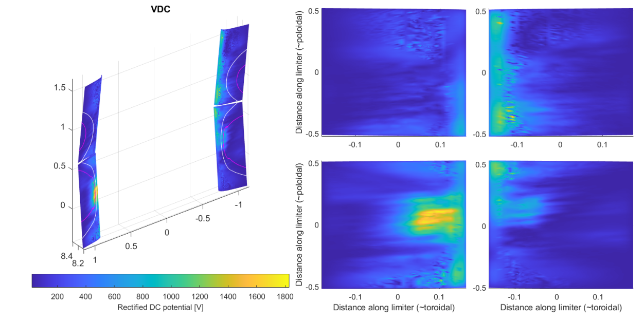


| Case | Plasma regime | Power | Peak | Dominant sheath characteristic |
| COMSOL | Low density | MW absorbed | kV | Resonance-cone localization () |
| COMSOL | High density | MW absorbed | kV | Field-aligned limiter streaks () |
| Petra-M | High density | MW absorbed | V | Field-aligned RF-active regions () |
| Present work | Wide-grid SOLPS-ITER | 7 MW coupled | kV | Mixed / accessibility |
Appendix B Benchmark of the GITR Thermal Sheath Model
The erosion calculations presented in this work use the GITR implementation of the Brooks magnetic pre-sheath formulation to describe ion acceleration through the combined Debye sheath and magnetic pre-sheath before impact on plasma-facing components. Because the resulting IEADs directly determine the geometry-specific effective sputtering yields, the underlying sheath electric-field and particle-trajectory models are benchmarked independently of the RF sheath calculations.
The GITR thermal sheath model is benchmarked with the analytical formulation developed by Borodkina et al. [34, 35]. The Borodkina model provides analytical descriptions of the near-wall potential distribution and ion trajectories for an obliquely incident magnetic field and has previously shown good agreement with fluid solutions and particle-in-cell simulations. The present comparison considers thermal sheath conditions only and therefore validates the near-wall electric-field and particle-acceleration model implemented in GITR, rather than the rectified RF sheath potentials computed using COMSOL.
Figure 22 illustrates the thermal sheath formulation implemented in GITR. As defined in Eq. 4 and Eq. 5, the total sheath potential is partitioned between the Debye sheath and the magnetic pre-sheath according to the local magnetic-field incidence angle. The corresponding normal electric field is represented by the sum of a rapidly decaying Debye-sheath contribution with characteristic scale and a more extended magnetic-pre-sheath contribution with characteristic scale . No additional sheath-potential expression is introduced here; the profiles shown in Fig. 22 are obtained directly from the formulation defined in the main text.
For nearly normal magnetic-field incidence, most of the potential drop occurs within the Debye sheath, and the potential approaches the plasma value over a relatively short distance. As the magnetic field becomes increasingly tangential to the surface, decreases and a progressively larger fraction of the potential drop is transferred to the magnetic pre-sheath. The potential profile therefore extends over distances comparable to the ion Larmor radius, modifying both the ion acceleration history and the resulting surface-impact distribution.
Figure 23 compares the normalized potential profiles obtained from the GITR implementation with those predicted by the Borodkina analytical model for magnetic-field incidence angles ranging from normal incidence, , to nearly grazing incidence, .
The two models exhibit close agreement over the full range of magnetic-field incidence angles considered. GITR reproduces both the characteristic potential variation near the surface and the progressive extension of the magnetic pre-sheath as the magnetic field becomes increasingly grazing. The agreement is particularly close for normal and moderately inclined magnetic fields. Relatively small differences develop at intermediate grazing angles, but the overall potential magnitude, spatial extent, and magnetic-field-angle dependence remain consistent with the analytical formulation.
A more direct test of the IEAD calculation is obtained by comparing the resulting ion impact-angle distributions. These distributions depend on the combined effects of the sheath electric field, magnetic-field geometry, initial ion velocity distribution, gyromotion, and particle integration through the near-wall region.

As shown in Fig. 24, the GITR and Borodkina impact-angle distributions agree closely for normal and moderately inclined magnetic fields (). Both models predict that the most probable impact angle shifts toward more grazing incidence as the magnetic field becomes increasingly tangential to the surface. For , GITR reproduces the same overall shift and narrowing of the impact-angle distribution, with only small differences in the peak magnitude and distribution width. These differences become more noticeable at the largest magnetic-field incidence angles, where near-wall ion dynamics are particularly sensitive to the partitioning of the sheath potential between the Debye sheath and the magnetic pre-sheath, as well as to the assumed ion distribution at the sheath entrance.
Taken together, Figs. 23 and 24 demonstrate that the GITR implementation reproduces the principal potential-profile and ion-impact-angle dependencies of the Borodkina analytical thermal sheath model. The benchmark therefore provides confidence in the near-wall particle acceleration and magnetic pre-sheath treatment used to generate the geometry-specific IEADs employed in the present erosion calculations.
This benchmark is restricted to thermal sheath conditions. For the RF calculations presented in the main text, the total rectified sheath potential is obtained from the nonlinear COMSOL RF sheath solution. GITR then applies the same benchmarked near-wall particle-acceleration framework defined in Eq. 4 and Eq. 5 to distribute the prescribed potential between the Debye sheath and magnetic pre-sheath according to the local magnetic-field incidence angle and to compute the corresponding charge-state-dependent IEADs.
Appendix C Global Tungsten Transport with GITRm
GITRm [44, 45] is a three-dimensional unstructured-mesh Monte Carlo particle-tracking code developed for impurity transport, plasma–material interaction, material erosion, and re-deposition in magnetically confined fusion plasmas. Built on the PUMIPic framework [46], GITRm employs fully three-dimensional tetrahedral meshes, allowing realistic representation of complex plasma-facing component (PFC) geometries such as the ITER ICRH antenna. The present calculations use the trace-impurity approximation, in which sputtered W impurities evolve within prescribed plasma and electromagnetic fields without modifying the background plasma. This approximation is appropriate because the tungsten density remains much smaller than the background plasma density throughout the simulations.
C.1 Transport Model
The impurity distribution function, , is evolved using the steady-state Boltzmann transport equation,
| (9) |
where and denote the impurity charge and mass, represents Coulomb collisions with the background plasma, and , , and represent primary sputtering, W self-sputtering, and atomic processes, respectively.
Particle trajectories are advanced by integrating the Lorentz force,
| (10) |
together with collisional slowing down,
| (11) |
where is obtained from the SOLPS-ITER plasma background. The electric field includes both the background plasma field and the RF sheath field imported from COMSOL, naturally incorporating RF sheath acceleration together with the associated drift.
The general GITRm formulation also permits inclusion of parallel thermal forces,
| (12) |
where
| (13) |
For the present ITER simulations, which are restricted to the upstream ICRH antenna region, the parallel ion-temperature gradients are comparatively weak. Consequently, the thermal-force contribution remains small relative to Lorentz acceleration and collisional slowing down and is therefore neglected. This approximation is not expected to remain valid in regions with strong parallel temperature gradients, such as the divertor
Cross-field turbulent transport is represented through anomalous diffusion,
| (14) |
where is the prescribed anomalous diffusion coefficient.
Ionization and recombination are treated using Maxwellian-averaged ADAS reaction-rate coefficients. For a reaction rate coefficient ,
| (15) |
with reaction probability
| (16) |
These processes determine the charge-state evolution and transport of sputtered tungsten throughout the ITER edge plasma.
C.2 Mesh, Plasma Mapping, and RF Sheath Coupling
The computational domain consists of a fully three-dimensional unstructured tetrahedral mesh representing the ITER first wall, ICRH antenna, limiter structures, and surrounding PFCs. Local refinement is applied around the antenna aperture, FS bars, and limiter sidewalls, while a coarser mesh is employed elsewhere to reduce computational cost.
The plasma background is obtained from the wide-grid SOLPS-ITER solution described in Section 2. Following the extrapolation procedure of Section 2.2, continuous distributions of , , , plasma flow, electric potential, and Ne charge-state densities are mapped onto the GITRm mesh assuming toroidal symmetry. Plasma quantities are interpolated to particle positions using linear finite-element interpolation.
The COMSOL-computed RF sheath potentials are mapped directly onto the antenna-facing surfaces. During particle integration, the local sheath electric field is evaluated using the Brooks sheath model together with the imported RF sheath potential, allowing particle trajectories to respond self-consistently to charge-dependent RF acceleration and magnetic-field incidence angle.
C.3 Particle Initialization and Numerical Configuration
Tungsten particles are initialized on the ITER ICRH limiter surfaces according to the spatially resolved gross erosion source obtained from STRIPE. The number of particles emitted from each surface facet is proportional to the local gross erosion flux and facet area, while initial energies and emission angles are sampled from a Thompson energy distribution and cosine angular distribution.
Particles subsequently undergo Lorentz acceleration, Coulomb collisions, ionization, recombination, anomalous diffusion, and repeated surface interactions. Upon striking a PFC, the impact location, charge state, energy, impact angle, and statistical weight are recorded to evaluate local redeposition and W self-sputtering. Net erosion is calculated from
| (17) |
Approximately computational particles are followed using a timestep of s for approximately timesteps ( ms physical time). The 100 ms transport interval was selected to characterize the finite-time migration of antenna-generated W while maintaining computational tractability for the full three-dimensional ITER geometry. Throughout the simulations, a constant anomalous tungsten diffusion coefficient of is employed. Statistical convergence is verified using the time histories of the area-integrated gross erosion, gross deposition, net erosion, and total tungsten inventory. Although the local gross erosion, gross deposition, and net erosion rates stabilize rapidly following the initial transient, the global tungsten inventory continues to evolve because of ongoing transport and redistribution throughout the ITER edge plasma. Consequently, the reported 100 ms results represent a finite-time transport assessment rather than a converged steady-state impurity inventory.
Simulations were performed using the distributed-memory implementation of GITRm on four NVIDIA A100 GPUs (80 GB per GPU). Spatial domain decomposition and MPI particle communication enable efficient simulation of millions of impurity trajectories within the full three-dimensional ITER geometry. A single 100 ms transport calculation requires approximately one month of wall-clock time on this computing configuration. Under the present ITER conditions, sputtered W atoms initially propagate ballistically as neutrals until ionization. After ionization, the resulting W ions become strongly magnetized and are transported predominantly along magnetic field lines, producing local redeposition while the remaining net erosion provides the source term for the global transport calculations presented in Section 5.
References
References
- [1] (2026) Calculation of the magnetic field and its modal analysis in the port plug cavity of the iter icrf antenna. EPJ Web Conf. 346, pp. 03010. External Links: Document, Link Cited by: §1, §3.
- [2] (2025) The iter icrf system under the new iter baseline: latest updates and technological developments. Note: Invited review talk, 25th Topical Conference on Radio-Frequency Power in Plasmas (RFPPC 2025), Schloss Hohenkammer, GermanyMay 19–22, 2025 External Links: Link Cited by: §1, §3.
- [3] (2024) Radiofrequency sheath rectification on west: application of the sheath-equivalent dielectric layer technique in tokamak geometry*. Nuclear Fusion 64 (12), pp. 126039. External Links: Document, Link Cited by: Appendix A, Appendix A, §1, §3, §3.
- [4] (2025) Integrated modeling of rf-induced tungsten erosion at icrh antenna structures in the west tokamak*. Nuclear Fusion 65 (), pp. 076039. External Links: Document Cited by: §1, §1, §3, §4.5.
- [5] (2026) Analysis of rf sheath-driven tungsten erosion at rf antenna in the west tokamak. EPJ Web Conf. 346, pp. 01004. External Links: Document, Link Cited by: §1, §1, §1, §3, §4.5.
- [6] (2026) Gyrotropy-induced symmetry breaking in rf-specific plasma wall interaction: mechanisms and mitigation strategies. Physics of Plasmas 33 (1), pp. 010701. External Links: ISSN 1070-664X, Document, Link, https://pubs.aip.org/aip/pop/article-pdf/doi/10.1063/5.0305554/20857881/010701_1_5.0305554.pdf Cited by: §1, §3.
- [7] (2025) Numerical assessment of icrf-specific plasma-wall interaction in the new iter baseline using the sswich-sw code. Nuclear Materials and Energy 42, pp. 101831. External Links: ISSN 2352-1791, Document, Link Cited by: §1, §1, §1.
- [8] (2025) Radiofrequency sheath rectification on the iter icrf antenna: results from comsol and petra-m. Nuclear Fusion. Note: to be submitted Cited by: §1.
- [9] (2024) Initial evaluations in support of the new iter baseline and research plan. Technical report Technical Report ITER Technical Report ITR-24-004, ITER Organization. Note: ITER Technical Report ITR-24-004 External Links: Link Cited by: §1, §2.1.
- [10] (2025) The new iter baseline, research plan and open r&d issues. Plasma Physics and Controlled Fusion 67 (6), pp. 065023. External Links: Document, Link Cited by: §1, §2.1.
- [11] (2024) Full w iter: assessment of expected w erosion and implications of boronization on fuel retention. Nuclear Materials and Energy 41, pp. 101789. External Links: ISSN 2352-1791, Document, Link Cited by: §1.
- [12] (2026) Erosion and impurity migration modelling in neon-seeded plasma discharges in iter with a full-tungsten wall. Nuclear Fusion 66 (9), pp. 096010. External Links: Document, Link Cited by: §1, §1, §4.5, §6.
- [13] (2024) ICRF-specific w sources: advances in minimization in asdex upgrade and near-field based extrapolations to iter with w-wall. Nuclear Materials and Energy 41, pp. 101742. External Links: ISSN 2352-1791, Document, Link Cited by: §1, §1, §3.
- [14] (2022) Characterizing w sources in the all-w wall, all-rf west tokamak environment*,**. Plasma Physics and Controlled Fusion 64 (10), pp. 104008. External Links: Document, Link Cited by: §1, §4.5.
- [15] (2023) Tungsten gross erosion and plasma impurity contamination in WEST phase 1: a statistical comparison of LH and ICRF-heated l-mode plasmas. In 29th IAEA Fusion Energy Conference (IAEA–CN–316), London, United Kingdom. Note: Paper IAEA–CN–316-2045 Cited by: §1.
- [16] (2026) Overview of material migration and erosion experiments in the full-tungsten west tokamak during phase 1 and phase 2 operations. Nuclear Fusion. External Links: Link Cited by: §1.
- [17] (2026) Erosion, migration and redeposition of w impurity on icrf antenna in high vs low density regimes. Nuclear Fusion. Note: Submitted Cited by: §1, §1.
- [18] (2026) Understanding carbon sourcing and transport originating from the helicon antenna surfaces during high-power helicon discharge in diii-d tokamak*. Nuclear Fusion 66 (9), pp. 096031. External Links: Document, Link Cited by: §1, §2.2.
- [19] (2021) Plasma edge simulations including realistic wall geometry with solps-iter. Nuclear Materials and Energy 27, pp. 100999. External Links: ISSN 2352-1791, Document, Link Cited by: §2.1.
- [20] (2024) SOLPS-iter modeling of the iter far scrape-off layer with realistic wall geometry. Nuclear Fusion. Note: submitted External Links: Link Cited by: §2.1, §2.1.
- [21] (2021) RF sheath induced sputtering on Proto-MPEX. I. Sheath equivalent dielectric layer for modeling the RF sheath. Physics of Plasmas 28 (9), pp. 093503. External Links: ISSN 1070-664X, Document, Link Cited by: Appendix A, §3.
- [22] (2021) RF sheath induced sputtering on Proto-MPEX part 2: Impurity transport modeling and experimental comparison. Physics of Plasmas 28 (10), pp. 103508. External Links: ISSN 1070-664X, Document, Link Cited by: §3.
- [23] (2017) Physics-based parametrization of the surface impedance for radio frequency sheaths. Physics of Plasmas 24 (7). Cited by: §3.
- [24] (2023) Magnetic potential based formulation for linear and non-linear 3D RF sheath simulation. Nuclear Fusion 63 (2), pp. 026024. Cited by: §3.
- [25] (2023) Using the stix finite element rf code to investigate operation optimization of the icrf antenna on alcator c-mod. Nuclear Fusion 63 (10), pp. 106006. External Links: Document, Link Cited by: §3.
- [26] (2010) Estimated density and temperature profiles in front of the ic iter antenna during burning flat-top (inductive scenario 1, 15 ma, ). Technical Report Technical Report ITER_D_33Y59M v2.3, ITER Organization. Note: ITER IDM Report Cited by: §3.
- [27] (2025) SOLPS-iter simulations of the iter divertor with improved plasma-facing component geometry. Nuclear Materials and Energy 42, pp. 101851. External Links: ISSN 2352-1791, Document, Link Cited by: §3.
- [28] (2017) Effects of outer top gas injection on icrf coupling in asdex upgrade: towards modelling of iter gas injection. Plasma Physics and Controlled Fusion 59 (7), pp. 075004. External Links: Document, Link Cited by: §3.
- [29] (2023) Parametric study of midplane gas puffing to maximize icrf power coupling in iter. Nuclear Fusion 63 (3), pp. 036008. External Links: Document, Link Cited by: §3.
- [30] (2026) Direct measurement of icrf-enhanced plasma potentials on west using reciprocating emissive probes. In EPJ Web of Conferences, Vol. 346, pp. 03007. External Links: Document Cited by: §3.
- [31] (2026) Experimental investigation of ICRF antenna operation and plasma-wall interaction in the regime of propagating slow waves in front of the antenna. Nuclear Fusion (submitted). Cited by: Appendix A, §3.
- [32] (1993) Sputtering data. Technical report Technical Report IPP 9/82, Max-Planck-Institut für Plasmaphysik (IPP). Cited by: §4.2.
- [33] (1990) Near‐surface sputtered particle transport for an oblique incidence magnetic field plasma. Physics of Fluids B: Plasma Physics 2 (8), pp. 1858–1863. External Links: ISSN 0899-8221, Document, Link, https://pubs.aip.org/aip/pfb/article-pdf/2/8/1858/12324124/1858_1_online.pdf Cited by: §4.3.
- [34] (2015) Application of analytical model of the electric potential distribution for calculation of charged particle dynamics in a near-wall layer and sputtering of the plasma facing surfaces. Russian Physics Journal 58 (4), pp. 438–445. External Links: Document, Link Cited by: Appendix B, §4.3.
- [35] (2016) An analytical expression for the electric field and particle tracing in modelling of be erosion experiments at the jet iter-like wall. Contributions to Plasma Physics 56 (6-8), pp. 640–645. External Links: Document, Link, https://onlinelibrary.wiley.com/doi/pdf/10.1002/ctpp.201610032 Cited by: Appendix B, §4.3.
- [36] (2013) RF sheath-enhanced beryllium sources at jet’s icrh antennas. Journal of Nuclear Materials 438, pp. S594–S598. Note: Proceedings of the 20th International Conference on Plasma-Surface Interactions in Controlled Fusion Devices External Links: ISSN 0022-3115, Document, Link Cited by: §6.
- [37] (2016) Estimates of rf-induced erosion at antenna-connected beryllium plasma-facing components in jet. Physica Scripta 2016 (T167), pp. 014035. External Links: Document, Link Cited by: §6.
- [38] (2023) Resonance cones in cold plasma: origin, singularities, and power flow. Physics of Plasmas 30 (10). Cited by: Appendix A.
- [39] (2024) The slow wave resonance cone in the collisional regime. Physics of Plasmas 31 (12). Cited by: Appendix A.
- [40] (2026) Power coupled to the slow wave resonance cone in cold plasma. In EPJ Web of Conferences, Vol. 346, pp. 01011. Cited by: Appendix A.
- [41] (2025) ICRF resonance cones in the low-density scrape-off-layer of ASDEX upgrade. Nuclear Fusion 65 (2), pp. 026019. Cited by: Appendix A.
- [42] (2023) Benchmark between antenna code topica, raplicasol and petra-m for the icrh iter antenna. AIP Conference Proceedings 2984 (1), pp. 060006. External Links: ISSN 0094-243X, Document, Link, https://pubs.aip.org/aip/acp/article-pdf/doi/10.1063/5.0162415/18090140/060006_1_5.0162415.pdf Cited by: Appendix A.
- [43] (2017) RF wave simulation for cold edge plasmas using the mfem library. EPJ Web Conf. 157, pp. 03048. External Links: Document, Link Cited by: Appendix A.
- [44] (2023) A 3d unstructured mesh based particle tracking code for impurity transport simulation in fusion tokamaks. Computer Physics Communications 292, pp. 108861. External Links: ISSN 0010-4655, Document, Link Cited by: Appendix C.
- [45] (2025) A gpu-accelerated 3d unstructured mesh based particle tracking code for multi-species impurity transport simulation in fusion tokamaks. Contributions to Plasma Physics 65 (5), pp. e202400073. External Links: Document, Link, https://onlinelibrary.wiley.com/doi/pdf/10.1002/ctpp.202400073 Cited by: Appendix C.
- [46] (2021) PUMIPic: a mesh-based approach to unstructured mesh particle-in-cell on gpus. Journal of Parallel and Distributed Computing 157, pp. 1–12. External Links: ISSN 0743-7315, Document, Link Cited by: Appendix C.