IMU-Aided Correction of Orientation-Induced Ranging Error in Bluetooth Channel Sounding on Commercial Hardware
Abstract
Bluetooth Low Energy Channel Sounding (BLE CS), standardized in Bluetooth Core Specification 6.0 (September 2024), enables distance estimation via phase-based ranging (PBR) and round-trip time (RTT). Although prior work has studied CS accuracy in configurations with a fixed orientation, no published work has studied how device orientation affects ranging error on commercial hardware. We present the first study of orientation-induced CS ranging error and a Machine Learning correction using IMU features. This study used the EFR32xG24 Channel Sounding Development Kit, the only commercial CS platform with an integrated six-axis Inertial Measurement Unit (IMU). Our results show that device orientation has a substantial effect on CS ranging accuracy; we found that a Random Forest model trained on the IMU derived orientation achieved a 74.6% Mean Absolute Error (MAE) reduction under a Leave One Orientation Out Evaluation, demonstrating that IMU readings have potential to improve ranging accuracy.
Index Terms:
Bluetooth Channel Sounding, device orientation, Inertial Measurement Unit (IMU), phase-based ranging, ranging correction, indoor localization.I Introduction
Bluetooth Channel Sounding (CS) is a significant improvement in short-range wireless distance measurement, as it estimates sub-meter distances with standard Bluetooth Low Energy (BLE) radios without the need of complex antenna arrays required by angle-of-arrival or angle-of-departure methods [1]. Standardized in September 2024 as part of Bluetooth Core Specification 6.0 [2], CS has been of interest in applications such as keyless vehicle entry, digital access keys, asset tracking, and proximity services: all contexts in which devices are carried in varying and uncontrolled orientations [3, 4].
BLE CS has two defined ranging methods. Phase-Based Ranging (PBR) estimates distance from the accumulated phase difference of signals exchanged across up to 72 channels in the 2.4 GHz band, while Round-Trip Time (RTT) estimates distance from the round-trip travel time of the signal [3, 5]. Both are sensitive to multipath propagation, which is determined in part by the radiation pattern of the device antenna. This pattern changes significantly when the device is rotated or tilted [6]. Silicon Labs, whose hardware is used in our study, acknowledges in their antenna design guidelines that device orientation has a significant impact on CS ranging accuracy, and that single-antenna configurations can produce errors of several meters depending on how the device is oriented [7].
Despite the impact orientation can have on accuracy, to the best of our knowledge, all published CS accuracy studies keep device orientation constant during measurement. Wieme et al. [8], the most comprehensive hardware evaluation of BLE CS to date, identified the onboard Inertial Measurement Unit (IMU) as a potential method for compensating for orientation-based ranging errors and explicitly left this as an open direction for future work. To the best of our knowledge, no subsequent study has addressed this gap.
This paper makes four contributions: (1) the first characterization of orientation-induced CS ranging error across nine orientations and nine distances; (2) the identification of a consistent asymmetry in ranging error between roll and pitch orientations; (3) a statistically significant correlation between IMU tilt and ranging error (, ); and (4) a Random Forest correction model showing 74.6% Mean Absolute Error (MAE) reduction after Leave-One-Orientation-Out (LOOO) evaluation across all nine orientations, demonstrating that IMU features generalize to unseen orientations. The system pipeline is illustrated in Fig. 1.
The remainder of the paper is organized into 5 sections. Section II covers related work on CS ranging, Machine Learning based correction approaches, and antenna orientation effects. Section III describes the methodology, particularly the hardware setup, data collection procedure, and feature computation. Section IV provides the results of this study, Section V analyzes these results by discussing our findings, and Section VI concludes the paper with future studies.
II Background and Related Work
There have been attempts at phase-based ranging for BLE before standardization by Zand et al. [9]. Woolley [3] defines PBR and RTT modes in Bluetooth 6.0. Gunia and Ellinger [10] compare CS against UWB and FMCW radar. Recent work has evaluated CS for vehicle access [4] and in challenging indoor environments [11].
The use of Machine Learning, specifically parametric neural networks, has been explored in correcting CS measurements [12]. MVDR-based pipelines have also been studied [13], with successful RMSE reductions of up to 0.4 m. It has also been shown that combining neural networks across several CS measurements improves accuracy [14]. Similar Machine Learning approaches for error correction in BLE multipath have been demonstrated [16, 17], and location-aware error correction has reduced UWB P90 ranging error by 58% to 15 cm on unseen trajectories [15]. However, none of these approaches solve orientation-induced ranging error, which is the novelty of this study.
There have been some studies showing the effect of antenna orientation. Dashti et al. [18] showed that directional antennas reduce UWB ranging error. Pasku et al. [19] showed that rotation about specific axes produces errors in RF space-diversity systems. Bou-El-Harmel et al. [20] showed that antenna orientation, including changes in polarization, changes indoor multipath characteristics in sensor networks. No peer-reviewed study isolates the effects of device orientation on CS measurements.

III Methodology
III-A Hardware and Firmware
In this study, two commercially available EFR32xG24 Channel Sounding Development Kits (BRD2606A) were used. One board was flashed with the standard Silicon Labs Reflector image and connected to a dormant laptop, while the other was flashed with a customized initiator image that reads and outputs the IMU measurements. The initiator was connected to a host laptop, which ran the Channel Sounding measurements in PBR mode with dual-antenna polarization diversity configured on both boards. The RTL library produced filtered measurements at approximately 8.9 Hz.
The default initiator firmware was modified to read the onboard ICM-40627 measurements immediately after each CS measurement in the main application loop. Blocking the BLE event callback with SPI reads caused buffer exhaustion on the reflector board; moving the IMU read to the main loop avoids this. For every entry recorded, the following features were captured: timestamp (ms), CS distance (m), (raw ADC, 16g, 2048 LSB/g), (raw ADC, 2000∘/s, 16.4 LSB/∘/s).
III-B Data Collection
Data was collected in an indoor, straight-line corridor with the reflector fixed at one end and the initiator placed at different distances. Nine distances were tested: 1 ft (0.30 m), 2 ft (0.61 m), 3 ft (0.91 m), 5 ft (1.52 m), 8 ft (2.44 m), 12 ft (3.66 m), 18 ft (5.49 m), 25 ft (7.62 m), and 30 ft (9.14 m). For each distance, nine orientations were tested: flat (face-up, reference), roll left 30, roll right 30, roll left 90 (vertical on long edge), pitch toward 30, pitch away 30, pitch toward 60, face down, and upright (vertical on short edge). Each configuration was recorded for 60 seconds at 8.9 Hz, yielding between 520 and 1,185 samples. In total, 44,576 measurements were recorded across 81 sessions. Throughout all sessions, the reflector was kept in a fixed flat orientation. The tile angle was calculated from the raw accelerometer readings using standard triaxial accelerometer tilt formulas [22], while gyroscope magnitude and ranging error were found directly from the raw gyroscope and CS distance measurements.
IV Results
IV-A Overview
The overall MAE across all measurements was 164.17 cm and the RMSE was 207.24 cm, primarily due to increased error at longer distances. At shorter distances between 1 and 3 ft, CS measurements are relatively accurate (MAE 19.70 to 39.15 cm). However, beyond 5 ft where indoor multipath becomes substantially worse, accuracy decreases severely, with MAE between 195 and 266 cm. This is consistent with prior indoor CS studies [8, 9].
IV-B Orientation Effect at Short Range
Across all orientation and distance combinations at short range, the lowest MAE was 9.29 cm at 2 ft pitching 30 degrees toward the reflector, which closely approaches the 10 cm ranging target stated by Hillyard et al. [5]. The highest short-range MAE was 57.57 cm, rolling left 90 degrees at 3 ft. At a fixed distance of 2 ft, different orientations produced a nearly 5-fold difference in MAE, from 9.3 cm (pitch toward 30) to 44.6 cm (roll left 90), demonstrating the impact orientation alone can have on ranging error. Table I shows the key orientation statistics at 1 to 3 ft.
| Dist. | Orientation | Mean err. (cm) | MAE (cm) |
|---|---|---|---|
| 1 ft | flat | 19.2 | |
| 1 ft | roll left 30 | 13.4 | |
| 1 ft | pitch away 30 | 23.6 | |
| 2 ft | flat | 36.3 | |
| 2 ft | pitch toward 30 | 9.3 | |
| 2 ft | roll left 90 | 44.6 | |
| 3 ft | flat | 44.9 | |
| 3 ft | pitch away 30 | – | 16.3 |
| 3 ft | roll left 90 | 54.6 |
The MAE is consistent across all orientations at 1 ft, with roll left 30 being the only orientation that produced a positive mean error. At 2 ft, pitching 30 degrees toward the reflector substantially outperformed other orientations, whereas rolling left 90 degrees showed high mean error and high variance. This high error in rolling left 90 degrees continued at 3 ft, suggesting a consistent increase in error at this orientation.
Rolling left 90 degrees at 18 and 25 ft showed the highest MAE across the set of orientation and distance combinations.
IV-C Roll vs. Pitch Asymmetry
Across every session, roll-axis orientations produce a combined MAE of 165.0 cm, whereas pitch-axis orientations produce a MAE of 140.9 cm, a ratio of 1.24. This is supported by the BRD2606A’s dual printed antennas being optimized for the horizontal plane. Rolling rotates both antennas away from their intended polarization alignment with the reflector, whereas pitching primarily changes elevation angle with less impact on polarization. The direction of pitch also matters, with pitching toward the reflector consistently outperforming pitching away at short range.
Fig. 2 shows mean error vs. distance for each orientation. Rolling left 90 degrees continues to show degrading accuracy at larger distances, while most orientations plateau after 12 to 18 ft. This suggests that rolling left 90 degrees introduces a severe antenna-alignment factor beyond the general multipath environment.

IV-D IMU Tilt Correlation
This study also observed a linear relationship between ranging error and tilt angle derived from the IMU measurements. The regression model produced for signed error and for absolute error, both with and thus statistically significant at . This shows that IMU-derived orientation features contain statistically significant information about CS ranging error, which prompted the correction model described in Section IV-E. The gyroscope magnitude shows a negative correlation with ranging error (, ), but this relationship is not meaningful: boards propped at low-error orientations using physical objects naturally introduce slight vibrations, which increases gyroscope readings despite the ranging quality being good.
Fig. 3 shows ranging error plotted against IMU-derived tilt angle. The positive slope of the linear fit shows that larger tilt angles are associated with larger absolute errors.

IV-E IMU-Based Correction
As explained in Section IV-D, the IMU features carry a statistically significant correlation with ranging error, which prompted the use of Machine Learning to correct that error using IMU measurements. A random 80/20 split gives 96.9% MAE reduction for the Random Forest, but this result is unreliable because consecutive measurements at the same orientation and distance are almost identical, making it very likely that similar data points appear in both training and testing. We therefore report two cross-validation strategies to obtain an honest measure of generalization.
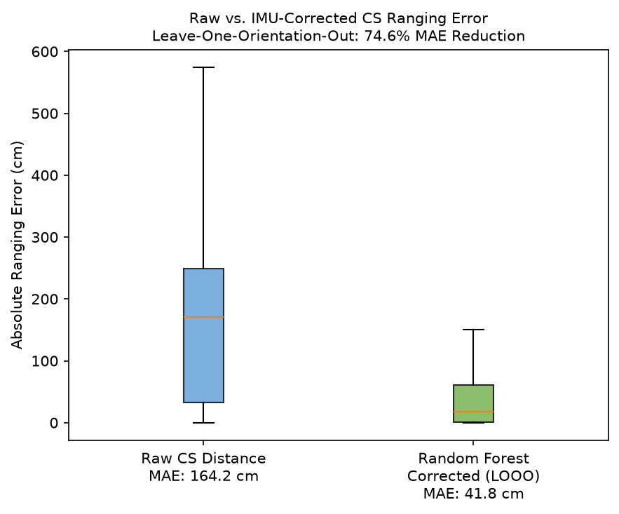
To select the best corrective approach, we compared three approaches under LOOO cross-validation. As shown in Table II, Random Forest substantially outperformed both Linear Regression and a more complex Multilayer Perceptron, achieving a 74.6% MAE reduction without having an inflated accuracy.
| Model | LOOO MAE Reduction |
|---|---|
| Linear Regression | 56.6% |
| MLP (6464) | 30.7% |
| Random Forest | 74.6% |
A Leave-One-Orientation-Out (LOOO) cross-validation trains on all orientations except one, tests on the completely held-out orientation, and averages across all nine tests. The Random Forest achieves 74.6% MAE reduction across all nine orientations, with individual orientation improvements ranging from 61.5% to 83.7%. This is especially significant since the model is evaluated on completely unseen orientations: despite only training on eight orientations, it is able to correct ranging errors for an orientation it has never seen. This is especially useful in applications such as keyless entry, where the object will undoubtedly be rotated in several ways.
A Leave-One-Distance-Out (LODO) evaluation trains on all distances except one and tests on the held-out distance, averaging across all nine distances. The Random Forest achieves an average 16.1% MAE reduction across all distances. Fig. 4 shows the error distributions before and after correction.
V Discussion
Two main device components explain the effects orientation has on accuracy. First, the BRD2606A’s antennas are designed to radiate the strongest signal when the board is flat. When the board is rolled or tilted, it points the strongest signal direction away from the reflector, which lowers the SNR and weakens the direct signal. Thus, the multipath signals make up a larger share of the total signal the reflector board receives [7, 21], increasing the ranging error.
Our 74.6% LOOO reduction shows that the Random Forest generalizes well to unseen orientations, and the 16.1% LODO reduction shows that the model also applies to unseen distances. The smaller LODO gain is somewhat expected, since distance affects raw ranging error more strongly than rotation does.
VI Conclusion
In this study, we present an evaluation measuring how device orientation can affect the accuracy of BLE Channel Sounding measurements. Using IMU measurements across nine orientations at nine distances, our results show that orientation has a significant impact on CS ranging performance. We also show that the already present onboard IMU on commercial hardware has enough information to meaningfully correct this error using Machine Learning approaches.
The applications of this study are important for any utilization of CS, in which the devices are handled in unrestricted orientations, such as keyless vehicle entry, asset tracking, and location based access control systems. Because of the little to none additional cost for IMU measurements, deployment is straightforward for this application. Future work should explore data collection across more environments to improve generalization and investigate the effect of reflector orientation on CS ranging accuracy, which was kept fixed in this study.
References
- [1] Bluetooth Special Interest Group, “Bluetooth Core Specification 6.0,” adopted 27 Aug. 2024.
- [2] Bluetooth SIG, “Now available: New version of the Bluetooth Core Specification,” Sept. 2024.
- [3] M. Woolley, “Bluetooth Channel Sounding: A technical overview,” Bluetooth Technology Website, 9 Jul. 2024.
- [4] L. Suresh et al., “BLE Channel Sounding: Novel method for enhanced ranging accuracy in vehicle access,” IEEE Access, vol. 13, pp. 67531–67547, 2025.
- [5] J. Hillyard, C. Bachmann, and L. Huang, “Bluetooth Channel Sounding: A step towards 10-cm ranging accuracy for secure access, digital key, and proximity services,” Bluetooth Technology Website, 30 Nov. 2023.
- [6] Bluetooth SIG, “Bluetooth Core 6.0 feature overview,” 2024.
- [7] Silicon Labs, “AN1493: Antenna Design Guidelines for BLE Channel Sounding,” 2024.
- [8] J. Wieme et al., “Performance evaluation of Bluetooth Channel Sounding on commercial hardware,” IEEE Access, vol. 13, pp. 180862–180876, 2025.
- [9] P. Zand et al., “A high-accuracy phase-based ranging solution with Bluetooth Low Energy,” in Proc. IEEE WCNC, Apr. 2019.
- [10] M. Gunia and F. Ellinger, “Channel sounding: Metrological exploration of the design options using related positioning systems,” IEEE Access, vol. 14, pp. 18913–18928, 2026.
- [11] M. Nikodem et al., “Experimental evaluation of multicarrier phase difference localization in Bluetooth Low Energy,” IEEE Sensors J., vol. 25, no. 1, pp. 1548–1560, Jan. 2025.
- [12] A. Tsemko, A. Santra, O. Kapshii, and A. Pandey, “Data-driven processing using parametric neural network for improved Bluetooth Channel Sounding distance estimation,” in Proc. IEEE ICASSP, 2025.
- [13] A. Santra, I. Kravets, N. Kotliar, and A. Pandey, “Enhancing Bluetooth Channel Sounding performance in complex indoor environments,” IEEE Sensors Lett., vol. 8, no. 10, 2024.
- [14] Z. Chen et al., “High-precision ranging fusion using neural network for Bluetooth Channel Sounding,” in Proc. WASA, Springer LNCS, 2025.
- [15] S. Coene et al., “Location-aware range-error correction for improved UWB localization,” Sensors, vol. 24, no. 10, 2024.
- [16] B. Bin Tariq et al., “Reduced complexity deep learning approach for Bluetooth ranging in multipath environments,” IEEE Sensors J., vol. 24, no. 19, pp. 31431–31441, Oct. 2024.
- [17] J. Van Marter et al., “Support vector regression for Bluetooth ranging in multipath environments,” IEEE IoT J., vol. 10, no. 13, pp. 11533–11546, 2023.
- [18] M. Dashti et al., “Antenna radiation pattern influence on UWB ranging accuracy,” in Proc. EuCAP, Apr. 2010.
- [19] V. Pasku, M. L. Fravolini, and A. Moschitta, “Effects of antenna directivity on RF ranging when using space diversity techniques,” Measurement, vol. 98, pp. 429–438, 2017.
- [20] A. Bou-El-Harmel et al., “Effect of quasi-isotropic antenna orientation on indoor multipath propagation characteristics in RSN applications,” Int. J. Antennas Propagation, 2017.
- [21] Silicon Labs, “UG615: EFR32xG24 Channel Sounding Dev Kit User’s Guide,” Mar. 2025.
- [22] M. Pedley, “Tilt Sensing Using a Three-Axis Accelerometer,” Freescale Semiconductor, Application Note AN3461, Rev. 6, Mar. 2013.