Imaging-System-Aware Inverse Design of
Information-Optimal Color Routers
Abstract
Nanophotonic color routers (CRs) are ordinarily optimized to steer predefined RGB bands into labeled subpixels under a single normal plane wave. A camera satisfies neither premise. Behind a lens every sensor position receives a spatially incoherent, finite-numerical-aperture pupil distribution that tilts with field position, and the four measurements that carry the most information about the color image need not resemble RGB filters. We inversely design a single-etch SiN CR under that field-dependent imaging-system illumination ensemble, at the tilt magnitude and azimuth a real sensor imposes, and score it not by RGB routing efficiency but by the imaging information the four raw measurements carry about the reconstructed CIE XYZ image. Re-scored under this ensemble, plane-wave-optimized designs lose most of the routing contrast they were credited with, so a structure that is optimal under a plane wave need not be the one a camera sees: the source used for optimization can change which design is selected. Under the illumination ensemble the CR collects the electrons of a color-filter array (CFA), but the tilted cone spreads each sorted spot so that less of it lands in the right site: on-axis throughput is against for the CFA, while routing purity is against for the CFA dyes. The two devices balance at a green-site signal-to-noise ratio of dB (read noise e- rms), below which the CR carries more information about the color image than the CFA. Reaching parity at full light against this reference CFA and camera model requires a pupil-averaged routing purity of , which we state as a design target for the architecture.
Keywords: color routers, metasurfaces, inverse design, camera pupil, computational color sensing
1 Introduction
Nanophotonic color routers (CRs) replace the absorptive color-filter array (CFA) [1] by sorting light by wavelength and steering each band to its target subpixel, so that nearly all incident photons reach the photodiodes, against through dye filters. The idea has been realized as dielectric color splitters and color-sorting metalenses [2, 3], plasmonic and Fano-resonant photon sorters [4], resonant-aperture and perfect-efficiency Bayer CRs [5, 6, 7], anti-Hermitian metasurface sensors [8], dielectric nanostructure RGB filters [9] and, in most of the recent literature, free-form structures obtained by adjoint, evolutionary or learning-based inverse design [10, 11, 12, 13], and prototyped on commercial submicron CMOS pixels [14]. All of them build on the flat-optics toolkit of dielectric metasurfaces [15]. The throughput argument is compelling for photon-starved capture, where the sensor is read-noise and shot-noise limited, not dynamic-range limited [16, 17, 18].
That gain carries a cost, since two premises near-universal in the CR literature are each violated by a camera.
The first premise concerns the source: a CR sorts color by angle-dependent interference, so its spectral response is tied to the illumination geometry in a way an absorptive filter never is. Published CR designs are optimized under a single normal plane wave [2, 10]. Behind a lens each cell instead receives a converging cone whose half-angle is set by the numerical aperture ( for a fast mobile lens) and whose axis is normal to the sensor only at the optical center, tilting by the chief-ray angle toward the corners and reaching for a microlens-shift-matched sensor [19, 20, 21]. Representing that finite--number illumination as an incoherent angular sum of plane waves is long established in CMOS pixel simulation [22, 20]. Oblique incidence has entered the CR literature only recently, and only as a tilted plane wave: robustness to a single tilted plane wave or to an averaged range of plane-wave angles [5, 23], and per-position chief-ray tilt across the full sensor plane [24], with Lee et al. using customized incident plane waves under non-periodic boundaries to suppress interpixel crosstalk [11]. A real pixel is lit not by a plane wave but by a converging finite-NA cone, and an extended scene delivers an incoherent superposition of such cones integrated over the pixel. No published CR is designed against that finite-NA cone, and none against the incoherent, field-dependent pupil ensemble it forms: the source this work optimizes inside the loop.
The second premise is that the CR should imitate a CFA: designs maximize the band-integrated transfer of prescribed bands into Bayer-labeled sites [10], a target that persists in fabrication-aware optimizers [25] and in dispersion-engineered RGB–NIR splitters [26]. Where a decoder appears it usually selects among finished designs instead of shaping them; Johlin ranks candidates by a color-corrected efficiency after optimizing a routing figure of merit [27]. End-to-end co-design of optics with reconstruction is established in broader imaging [28, 29], and recovery-oriented color design has a long history in color engineering, from filter-set goodness measures [30] to spatio-spectral mosaic design for optimal recovery [31]. A parallel line designs and scores imaging encoders by the task information their raw measurements carry rather than by a resemblance target [32, 33]. We are not aware of a physical four-site color router optimized this way, with a full-wave forward model and the decoder inside the objective, under the source a camera delivers.
A color router is usually posed as a structure that routes predefined RGB bands into labeled subpixels; we reframe it instead as a generalized color router (CR), a passive four-site spectral encoder whose four responses – carry no intrinsic color identity, and we ask which four measurements are most informative about the reconstructed color image under the source a camera actually delivers. Two ideas make this concrete. First, the field-dependent imaging-system illumination ensemble enters the design loop as the native input: each sensor position is assigned the entire two-dimensional, spatially incoherent finite-NA distribution on the tilted exit pupil, and the plane-wave responses are summed incoherently with the physical pupil weights before any figure of merit is formed. Second, the decoder sits inside the gradient: for every geometry we re-solve the optimal linear decoder in closed form and differentiate the imaging information it leaves back through the pupil average and the electromagnetic solver, so that Maxwell’s equations and the color prior jointly choose the four measurements. Together these change what is optimized, from band-pass resemblance to information-optimal measurement, and they change which structure the optimizer selects: the design that is optimal under a plane wave is not the one the illumination ensemble picks (Fig. 1).
Deploying such designs across a real sensor is then an engineering consequence, not a separate idea. Because the pupil shift carries a magnitude and an azimuth, the response varies over a two-dimensional field; we tile it with rings in chief-ray angle crossed with graded azimuth sectors, and the symmetry of the square four-site lattice reduces the deployed regions to six designed masks. Under this source the CR does not overtake the CFA at nominal exposure; what limits it is where the sorted light lands rather than how much of it arrives, and below a green-site signal-to-noise ratio of dB it carries more information about the color image than the CFA.

2 Source model and objective
A cell at sensor radius is illuminated by a converging cone of numerical aperture NA whose axis is tilted by . Write for the cell area and, for pupil direction and a fixed incident polarization, let be the simulated detector-plane field and its energy in site . Responses are calibrated to the cell-total transmitted power,
| (1) |
with the longitudinal-power-normalized total transmittance. The vectorial Debye–Wolf field of one scene point focused at transverse position is the coherent superposition of pupil plane waves [34, 35, 36],
| (2) |
where is the direction-cosine area element, the polar angle referred to the sensor normal, and the transverse wavevector. Because is the solid-angle element, Eq. (2) describes a pupil of uniform radiance, a modeling choice that differs from the aplanatic apodization of a sine-condition Richards–Wolf pupil [35, 36] by in intensity across the disk, and at an oblique field point the difference becomes an asymmetry across the tilted disk. Pupil weighting and the rigid circular shape assumed off axis both belong to the camera model, whose scope is set out in Sec. S1.
A detected quantity is quadratic in the field, so the cone focused at contributes both diagonal and cross terms in . For a scene that is spatially incoherent and locally uniform, the focus position is distributed over many cell periods, and averaging over annihilates the off-diagonal phases. The surviving quantity is the incoherent aggregate
| (3) |
Equation (3) is a quadrature of over the shifted pupil. It becomes exact in the infinite-uniform-support limit under three conditions: a scene incoherent and uniform over a patch large compared with the coherence radius m at nm, a lens shift-invariant over the cell, and an array of identical periodic cells. The complete cross-spectral-density derivation, the van Cittert–Zernike coherence scale [37, 38, 39] and the finite-support residue are given in Sec. S1. Here acts as a cell-total-power-calibrated site-partition proxy: the total is power-normalized, while its allocation among the four sites uses an electric-energy partition in place of a per-well Poynting-flux or carrier-generation calculation.
Cone diffraction, aperture convolution, neighboring-cell spill and the chief-ray tilt are all carried by the single weight set , which is independent of the CR and computed once; spill cancels only because the construction is flat-field and infinite-periodic. We normalize the weights to an assumed relative-illumination model, imposed as a placeholder for lens data, since CRA-matched modules with shifted microlenses commonly fall off more slowly [40, 20, 41]. The tilt shifts every sample on the disk,
| (4) |
so the source is a function of two field coordinates, the tilt magnitude and the tilt azimuth . The stack is air above the patterned layer and oxide below it, with the detector plane in the oxide. All pupil directions, the disk radius and are specified on the air side, so every angle quoted here is air-side. Optimization uses an eight-ray, two-polarization reduction of the shifted-disk pupil quadrature, and every reported value uses the corresponding sixteen-ray rule; both are part of the camera model. The reduction is verified three ways in Sec. S1 [35, 42, 36].
The CR is a passive four-site spectral encoder. Its four responses carry no R, G or B identity, and nothing in the objective rewards resemblance to a dye band-pass. Let be a reflectance spectrum on the evaluation grid and the relative spectral power distribution of the illuminant. The colorimetric target uses the energy quadrature of the CIE color-matching functions [43], whereas photoelectron sensing uses the photon quadrature,
| (5) |
with a common representative back-side-illuminated silicon quantum efficiency [44]. Retaining the wavelength factor before the photon-defined is what makes an electron operator; the common constants are absorbed into the exposure scale. The four-site signal is , with a signal-dependent covariance built from the expected charge and an added read term. Given the spectral second moment of the reflectance prior [45], the linear decoder that minimizes the color error is available in closed form and is re-solved at every iterate, so the geometry is differentiated through the decoder rather than against a trained one. Equation (7) is that estimator with the decoder marginalized.
The design objective is the imaging information , the mutual information between the four noisy raw measurements and the CIE XYZ image the camera is asked to deliver. Under the Gaussian model of Sec. 2 it has the closed form
| (6) |
in which the are the generalized eigenvalues of the posterior color covariance against the prior one, that is the three roots of , with
| (7) |
and the measurement matrix that carries the scene latent into expected charge and the signal-dependent shot-plus-read covariance of Sec. 2. Each is the fraction of the prior color variance that survives the measurement along one principal direction of the color space, so and is the number of bits the four sites deliver about that direction; the sum runs over three because the target is three-dimensional. A device that measured nothing would leave every and . The sum is therefore the log-volume by which measuring the four sites shrinks the uncertainty about the color of the scene; the factor rather than divides that cell quantity among the four raw pixels it spans, so and every value quoted below are in bits per raw pixel and compare directly with a CFA on the same sensor. It accumulates photon collection, quantum efficiency, shot and read noise, the exposure ladder and the irreducible uncertainty that lies outside the measured spectral latent.
is invariant under any invertible linear map of the four measurements, so it never rewards a design for resembling red, green and blue channels, and the site permutations that deployment induces cost nothing. It marginalizes the optimal linear decoder analytically rather than training one. And because it is an information rather than an error, it composes across the exposure ladder without a choice of quality target: a device that carries more bits carries them at every rung. That ladder is five reference-CFA-green levels, e- against a e- reference, entering with equal weight and averaged after the logarithm rather than by averaging posteriors; the nominal exposure below is the ladder at unit scale, a mean green-site charge of e-, and every exposure and signal-to-noise figure is referred to it. The optimization schedules and the noise model are specified in Secs. S4 and S8.
The four channels are exchangeable: a site has no intrinsic color identity, only the one the CR and the per-region decoder assign it, so any relabeling is absorbed by the decoder at no optical cost. And the reference camera is defined on the same footing: the CFA baseline uses a broad primary-pigment transmission stand-in constructed from the published dye-filter literature, together with an microlens efficiency [46, 47, 19, 20, 41], four quarter-area sites, and the same illuminant, relative illumination and quantum efficiency, so that a comparison at a given field point turns on the optical layer alone.
3 Plane-wave optimization can select the wrong design
We scored nine single-layer CRs produced here at a range of heights and CR-to-detector distances twice, each at its own geometry: once under the normal plane wave the published recipes optimize and certify against, and once under the illumination ensemble on axis. Six of the nine exceed the filter-array reference under the plane wave, and none does under the ensemble.
What changes is the ordering, not only the level (Fig. 2). A plane-wave ranking carries little information about camera performance: the two columns correlate at only , and a wider set of twenty designs, including two-layer stacks and a second material, gives the same picture. The design with the highest plane-wave score among the nine, bit, falls to bit under the ensemble and is beaten there by one that scored bit under the plane wave, and in the wider set the design that is best under the ensemble ranks tenth under the plane wave; Fig. 3 shows the same collapse at the response level on the highest-scoring mirror-symmetric design. The drop itself is design-dependent, between and bit, which is why it cannot be absorbed into a constant correction: a plane-wave evaluation is an unrelated ordering, not a conservative estimate of camera performance.

We take a representative prior design and re-evaluate it unchanged under the illumination a camera pixel receives: the illumination ensemble evaluated on axis (), the most benign position on the sensor. The in-band routing contrast of a band is the band-averaged excess of that band’s routed fraction into its target site over the Bayer-area floor. Retention is that contrast under the illumination ensemble divided by its value under the normal plane wave, so retention means the change of source costs nothing and retention is the random-routing floor. The structure is a re-implementation from the published geometry, evaluated twice on one common oxide-embedded stack at the same raster and order truncation, so that the only variable between the two evaluations is the source.
A plane-wave-optimized CR of the MCR type, in the dielectric color-splitter lineage of Ref. [2], retains of its in-band routing contrast in red, in green and in blue: a structure certified under a plane wave keeps only part of its sorting once the same geometry meets the incoherent cone a pixel receives, and off axis the chief-ray tilt compounds the loss.
Retention is not defined for the designs reported here: optimized against a reconstruction objective, their in-band routing contrast sits at or below the Bayer-area floor under both sources.
A control that optimizes under each source, rather than re-scoring one design, isolates the same effect from the initialization: run from a common cold start, the recipe reaches a higher-scoring design under the pupil ensemble than under a single normal plane wave on both seeds tried, scored under the shared sixteen-ray evaluation (mean bit per raw pixel; Fig. S12).
4 Design and deployment
Every design reported here is one free-form binary pattern in a single SiN layer on a m four-site cell, exposed to air above an oxide substrate, at a common height nm: one deposition and one etch for the whole wafer, with the regions differing only in the lithography pattern, which is position-dependent in any case. A back-illuminated CMOS stack would ordinarily planarize such a layer in oxide [48, 17], dropping the index contrast from to and weakening the achievable routing. However, the designs reported here keep the air interface above the pattern; integrating them in a planarized stack would mean recovering that contrast with height or index, and is outside the scope of this work. SiN was selected over TiO2 and a hydrogenated a-Si:H model by a preliminary platform comparison, on process grounds and on residual blue absorption respectively [49, 50, 51, 52]. Dispersion uses measured optical constants for SiN [53] and SiO2 [54]. Each pupil plane wave is one rigorous coupled-wave analysis solve [55, 56, 57, 58, 59] in the differentiable GPU implementation TORCWA [60]. We parameterize the pattern as a latent field, upscaled to the raster through a conic filter of radius nm and a tanh projection in the robust erosion/dilation formulation [61, 62, 63], so the latent pitch and the filter scale coincide at nm and the free parameters number , far fewer than the raster cells (Fig. 4). Off-diagonal design azimuths break the mirror of the cell, so every off-diagonal response uses the full two-polarization path. The patterns themselves are left unconstrained for the same reason: away from the axis the incident ensemble is already asymmetric, so a mirror imposed on the pattern matches no symmetry of the problem and only removes degrees of freedom. Figure S9 puts a number on what it costs. Detector-plane conventions, the fill-factor assumption, the differentiable surrogate and the hard-mask evaluation settings are specified in Sec. S2.

Equation (4) displaces the whole pupil disk by a vector with a magnitude and a direction, so the effective source lives on a two-dimensional domain , the domain covered by the architecture developed below. The CFA is insensitive to that second coordinate, because dye absorption is isotropic to first order, so a Bayer CFA is azimuthally flat by construction. A CR responds to it, for two reasons: it sorts color by interference between scattered orders whose relative phases are set by the incident direction, and the square four-site lattice it sorts into is itself anisotropic. At the cone axis runs along one site diagonal, at along the other, and at along the cell edges, so the same fixed pattern and site assignment meet different incidence geometries as turns.
Carrying one mask across the field is expensive: the on-axis design of Sec. 5, re-evaluated unchanged at the six calibration slots, falls from on axis to at twenty degrees, and its deficit against the CFA widens from to bit. A design family certified along a single diagonal degrades the same way in azimuth. No single cell covers , and the field must be partitioned in both coordinates.
The partition uses rings –, – and – in chief-ray angle with design centers , crossed with azimuth sectors whose widths narrow outward: eight sectors in ring 1, sixteen sectors in ring 2 and twenty-four sectors in ring 3, with the sector edges placed on the symmetry axes so that no sector straddles one. The grading follows from geometry: an azimuth mismatch displaces the pupil disk along a chord that grows with chief-ray angle, so the adopted half-widths hold the center-to-edge displacement below of the pupil radius in every ring, against the a uniform sector would produce at ring 3 (Sec. S5).
Only the first-quadrant wedge must be designed. The eight isometries of the square lattice map the four-site cell onto itself, so applying one of them to a pattern gives an exact solution of Maxwell’s equations at the mapped azimuth with the same fields relabeled. The only consequence is a static permutation of the four sites, and that costs nothing precisely because the sites carry no color filters. The orbit of a design azimuth is not a uniform comb, so the wedge centers were chosen so that their orbits tile each ring exactly; the arithmetic and the conditions under which the improper elements apply are given in Sec. S5. The six wedge designs – of Fig. 6 serve all regions, with no azimuth served off a design axis by more than its sector half-width, and cover a sensor whose corner chief-ray angle is in full. Extending the architecture to a larger corner would require a fourth ring, which we leave to future work.
Exact deployment under still leaves each sector to be designed on its own, because the symmetry transports a pattern to a mapped azimuth without keeping it optimal as the chief-ray direction moves. Each of the six was therefore refined at its own slot, starting from the carried on-axis mask, under an exact hard-mask acceptance test. Designing each sector separately changes where the field is weak, not only how well it performs on average. Carried unchanged across the field, the on-axis mask trails the CFA by bit at the center and bit at the corner; the six per-slot designs hold that deficit between and bit at every slot (Fig. 5). As a result, the worst position on the sensor improves by bit and the spread across the field narrows from to bit. Spatial uniformity of color response is a separate requirement from mean performance in a camera, and it is the one that microlens shifting and chief-ray-angle matching already exist to meet [20, 40].
The mean gain is bit, area-weighted over the covered field. It is zero on axis by construction, since every run was warm-started from the carried mask and floored at it, and it grows with chief-ray angle: to bit in ring 2 and to bit in ring 3. Within ring 3 the three design azimuths differ by more than a factor of two, which is the azimuth dependence of Sec. 4 measured on the deployed set rather than inferred from the pupil geometry.
The three ring-3 designs are not equally converged. gains bit against and for its neighbors and carries the largest residual deficit at bit, while across its own sector it loses least of the three; the difference is in the search, not the field point, and a better-converged would narrow the spread quoted above.
Each mask serves a whole sector, so it is re-checked at both edges of its own sector. No design loses more than bit relative to its design axis, so no position is served more than that below the slot that serves it.

The channel spectra of the designs reported below settle the qualitative question on their own. Figure 7 shows the four absolute site responses of the six designed masks at their own field points. Each is broadband, all four overlap, and their ordering in wavelength shifts from one design to the next. This follows directly from what was optimized: nothing in Eq. (6) rewards resemblance to a dye filter, so the designs buy conditioning of and photons instead of band resemblance. Sharp spectral sorting requires strongly resonant, therefore angle-sensitive, scattering, and the ensemble averages resonance positions over inside the oxide ( in air). It is the same smoothing that flattens the plane-wave spectra of Fig. 3. Throughput, conditioning, decoder noise gain and residual color bias jointly set the worth of such a spectrum, and Section 5 evaluates all four.
5 Crossover with the CFA
The comparison is made against a CFA sharing the lens, the aperture, the quantum efficiency, the exposure ladder and the noise model, and it is made in imaging information, the quantity the design objective optimizes.
For each sensor position we form its response by folding the azimuth into the fundamental wedge, selecting the assigned design and its site permutation, and bilinearly interpolating the direct response nodes; the analytic factor is removed before interpolation and re-evaluated at the requested coordinate. Reconstruction is a four-channel linear demix over –: unlike a Bayer CFA, whose two green sites are identical and averaged, a CR makes them distinct off the design axis, so averaging them would discard a real channel. Both cameras share the same scene, exposure, illumination, field quadrature and frozen signal-dependent noise draws, and the quantum efficiency enters identically at raw formation, in the decoder response matrix and in the noise calibration. We score each sensor position on a natural-scene tiling of measured reflectance spectra; the field-weighted comparison is Fig. 5. That evaluation weights the six design field points by solid angle across the domain the ring set covers.
The comparison is a local colorimetric evaluation: each position is driven by the incoherent ensemble response of a locally uniform patch on isolated periodic cells, so spill into and out of a cell cancel by periodicity, and object-space convolution, spatial-frequency response and edge color lie outside it. The kernel that such a calculation would require is defined separately in Sec. S6. The signal coordinate, in turn, is a normalized CFA-green level and carries no absolute ISO or electron calibration [64].
At the on-axis slot the best mask reaches bit against bit for the matched CFA (the CFA simulated at the same field point, through the same pupil), so at the nominal exposure the CFA leads by bit. That ordering is not fixed, because the two devices fail in different currencies. The CR sorts rather than absorbs and delivers the electrons on the quantum-efficiency-weighted basis, an advantage worth more as photons become scarce, while the CFA separates color with dyes whose transmittances are near-copies of the color-matching functions, an advantage independent of light level. Scanning the exposure locates the balance (Fig. 8). Below a green-site signal-to-noise ratio of dB (an amplitude ratio, , corresponding to e- per green site, a fifth of the nominal exposure), the CR carries more information about the color image, by up to bit at the dim end of the scan. Above it the CFA leads, and the gap widens to bit at three times nominal, the brightest exposure scanned, because the deficit there is structural rather than noise-limited. Figure 9 shows what that costs in a recovered color image: at dB the CR reconstructs at dB peak signal-to-noise against the CFA’s , and at dB at against , the lead growing as light grows scarcer; at the nominal exposure the ordering reverses, and two conditions travel with that crossing: it is computed at a read noise of e- rms, a noisier detector moving the crossing toward brighter scenes, and the illuminance it corresponds to follows from the exposure ladder of Sec. 2, not a photometric measurement.

Decomposing both responses in the same units locates the shortfall. Writing the pupil-averaged site response as a throughput multiplying a mixture of a perfectly sorted allocation and a flat one, with the mixing weight the effective purity fitted over the site assignments that no dye fixes, the design here reaches on axis against for the CFA: essentially all of the incident light arrives somewhere on the detector, but it is not sorted. The pupil-averaged effective purity is , against for the same mask at normal incidence and for the CFA’s dyes. The shortfall is a lateral walk-off: at the marginal ray crosses the CR-to-detector gap at an angle, and because the interfering diffraction orders sit far apart in angle the displacement exceeds the paraxial estimate by a factor of to and grows with wavelength, spreading each spot over a disk of – m across a m site. A CR separates colors by pushing them sideways by half a site; the disk radius, – m, is comparable to that displacement, which is why so little of the sorting survives. Scored ray by ray, purity falls with pupil radius, from on the innermost quadrature radius to on the outermost, while throughput stays flat across the aperture (Fig. 10).

Because the objective is a smooth function of throughput and purity, parity with the CFA can be stated as a number: at a CR matches the reference CFA and camera model used here when its pupil-averaged effective purity reaches , a value that moves by less than across the site-to-band assignments and is therefore a property of the comparison rather than of any labeling. The bar is quoted at the on-axis throughput and rises as light is lost off axis, where the measured purity also falls, so the shortfall is wider at the corner than the it is on axis. The same effective-purity bar applies to any future architecture, whether taller stacks, several patterned layers or a different index system. The mask holds even at normal incidence, below the bar before any cone is applied, so the shortfall is not the cone erasing an otherwise sufficient design: parity requires raising the normal-incidence purity itself and then holding it through the aperture.
6 Fabrication tolerance
The differentiable forward model is cross-checked against an independent time-domain solver in Sec. S2; here we bound how the reported masks respond to fabrication error. Perturbing the reported mask by one raster pixel of critical dimension ( nm erosion or dilation) and by of height moves the throughput by at most but costs up to bit of imaging information, three fifths of the on-axis deficit against the CFA, dropping the effective purity from to while the collected power is unchanged. The process requirement therefore falls on critical dimension, not on layer thickness, and does not appear in the throughput figures. One raster pixel is about a third of the nm design feature, so these are upper bounds rather than projections at achievable control.
Free-form optimization on a fine grid readily produces sub-fabrication features [65, 66, 63]. The latent field with robust erosion/dilation bounds the design’s spatial-frequency content at one latent cell, nm, but that bound applies to the parameterization and not to printed geometry: a projection threshold can place a level crossing arbitrarily close to a latent node, leaving isolated structures a single raster pixel across. The masks reported here have every such island of solid and hole of void removed. Deleting them costs to bit, so they are artifacts of the threshold rather than features the design uses; deleting more is not free, with everything up to nm costing to bit and up to nm costing to bit.
After that removal the narrowest cross-section is nm in four of the six designs and nm in the other two, where a neck inside a larger feature survives an area threshold. Against the nm layer those are etch aspect ratios of and . Necks at that scale belong to the class that lithographic proximity correction addresses [67], and high-aspect-ratio SiN etching is an active capability [52, 51]. Furthermore, the tiling itself adds no process step: all regions share one deposition, one etch and one height, and differ only in a lithography pattern that is position-dependent in any case.
7 Discussion
The reconstruction used here is simple by construction: a linear demix solved analytically at every iterate inside the design loop. No network is learned and no iterative inference is run, so the encoder–decoder relationship stays interpretable and the gradient that shapes the geometry is the gradient of the information the modeled camera collects. Replacing the CFA commits the camera to a computational front end in any case, since broadband free-form responses do not suit the conventional narrowband white-balance/color-correction/demosaic chain [68, 69]. Over that front end the device adds a per-region matrix of the same class as a color-correction plus shading-correction stage, a static site-permutation table and a -entry region map fixed at design time. Those are the same class of calibration data as lens-shading or CRA-correction grids [20, 40], and non-Bayer mosaics have shipped with mosaic-aware processing before [70]. Our evaluation refits the decoder at every sampled field coordinate and exposure, so an implementation would need a calibrated table or a validated interpolation of one.
The crossing marks the regime where the CR leads: an information-optimal CR is a photon-starved color sensor. Below it the CR collects light the CFA absorbs and converts that into more information about the color image; above it what limits the CR is not how much light it collects but how little of it lands in the right site, a shortfall the cone deepens and does not create, and the CFA wins. Designs that move the balance follow from the same loop. A taller or multi-layer sorter could restore sharper spectral sorting under the ensemble [3, 6, 12]; a hybrid CR-plus-thin-dye stack would trade a little light for bright-light spectral cleanliness; an RGB–IR variant could be designed against the same tilted pupil [5, 26]; and a fourth ring would extend the tiling to sensors whose corner chief-ray angle exceeds .
The illumination is a camera-pupil model: a rigidly shifted circular disk of uniform radiance sampled by a fixed quadrature and normalized to an assumed relative illumination for an ideal lens. The electromagnetic evaluation uses isolated periodic cells, so interpixel crosstalk and the behavior at the mask discontinuities between regions lie outside it [11, 71]. The comparison is colorimetric and local: the finite-numerical-aperture pupil is the modeled source, and the metric is its zero-frequency limit. The modulation transfer that rolls off at higher spatial frequencies, shared by any detector behind the same lens, and the edge color the router adds are characterized in Sec. S6 rather than folded into the score.
8 Conclusion
A camera color router is ill posed as a device that routes predefined RGB bands under a selected plane wave. Every sensor position receives a field-dependent, spatially incoherent finite-NA pupil distribution, and the four measurements that best reconstruct color need not resemble RGB filters. Putting both facts inside one differentiable loop, with the illumination ensemble as the native source and an analytically solved response-aware decoder inside the gradient, yields four unlabeled, broadband channels on a single SiN layer nm tall, exposed to air above an oxide substrate, one deposition and one etch, on a nm latent grid. The pupil shift carries an azimuth as well as a magnitude, and one mask carried across the field trails the CFA by bit at the center and bit at the corner; designing per sector holds that deficit between and bit, and the symmetry of the four-site lattice serves all regions from six designed masks.
Judged as imaging information under the source a camera actually delivers, the CR does not replace the CFA at the nominal exposure: on-axis throughput is already and the deficit is entirely in where the sorted light lands, deepened by the cone but short of the bar even without it, so the two devices meet at a green-site signal-to-noise ratio of dB and the CR belongs where photons are scarce.
This reframes the design problem: the lever is no longer RGB routing efficiency under a plane wave but two quantities measured after reconstruction under the real source: the light level at which the CR overtakes the CFA, and the pupil-averaged routing purity that fixes it. For the reference CFA and camera model considered here, reaching parity at full light needs a pupil-averaged purity of at throughput , against for this design; pushing the crossing toward brighter scenes, or lifting purity toward that bar, is the direction we point to, with taller or multi-layer sorters, hybrid router-plus-dye stacks and richer measurement models the natural places to look. Whichever route, the quantity a camera color router should be optimized and reported against is the imaging information under the illumination ensemble it actually receives, not the routing contrast under a plane wave.
Acknowledgements
Y.P. acknowledges the support by the Basic Science Research Program through the National Research Foundation of Korea (NRF) funded by the Ministry of Education (RS-2020-NR049597), and the creation of the quantum information science R&D ecosystem (based on human resources) through the National Research Foundation of Korea (NRF) funded by the Ministry of Science and ICT (RS-2023-00256050).
Conflict of Interest
The authors declare no conflict of interest.
Data Availability Statement
A reference implementation of the core method (the camera-pupil forward model and the imaging-information objective) is available at https://github.com/hyoseokp/information-optimal-color-router. The derived response caches, binary masks, random seeds and analysis environment needed to reproduce the figures are available from the corresponding author upon reasonable request.
Author Contributions
H.P.: methodology, software, simulation, analysis, and writing of the original draft. Y.P.: conceptualization, supervision, writing (review and editing), and corresponding author.
References
- Bayer [1976] Bryce E. Bayer. Color imaging array, 1976. URL https://patents.google.com/patent/US3971065A/en. U.S. Patent 3,971,065, filed 5 March 1975, granted 20 July 1976, assignee Eastman Kodak Company.
- Nishiwaki et al. [2013] Seiji Nishiwaki, Tatsuya Nakamura, Masao Hiramoto, Toshiya Fujii, and Masa-aki Suzuki. Efficient colour splitters for high-pixel-density image sensors. Nature Photonics, 7:240–246, 2013. doi: 10.1038/nphoton.2012.345.
- Miyata et al. [2021] Masashi Miyata, Naru Nemoto, Kota Shikama, Fumihide Kobayashi, and Toshikazu Hashimoto. Full-color-sorting metalenses for high-sensitivity image sensors. Optica, 8:1596–1604, 2021. doi: 10.1364/optica.444255.
- Laux et al. [2008] Eric Laux, Cyriaque Genet, Torbjorn Skauli, and Thomas W. Ebbesen. Plasmonic photon sorters for spectral and polarimetric imaging. Nature Photonics, 2:161–164, 2008. doi: 10.1038/nphoton.2008.1.
- Zhao et al. [2021] Nathan Zhao, Peter B. Catrysse, and Shanhui Fan. Perfect RGB-IR color routers for sub-wavelength size CMOS image sensor pixels. Advanced Photonics Research, 2:2000048, 2021. doi: 10.1002/adpr.202000048.
- Catrysse and Fan [2026] Peter B. Catrysse and Shanhui Fan. A single-layer color router for solid-state image sensors. Applied Physics Letters, 128(9):091104, 2026. doi: 10.1063/5.0307556.
- Shao et al. [2025] Yifan Shao, Rui Chen, Yubo Wang, Shuhan Guo, Junjie Zhan, Pankaj K. Choudhury, and Yungui Ma. Pixelated Bayer spectral router based on a sparse meta-atom array. Chinese Optics Letters, 23(7):073601, 2025. doi: 10.3788/COL202523.073601.
- Smalley et al. [2020] Joseph S. T. Smalley, Xuexin Ren, Jeong Yub Lee, Woong Ko, Won-Jae Joo, Hongkyu Park, Sui Yang, Yuan Wang, Chang Seung Lee, Hyuck Choo, Sungwoo Hwang, and Xiang Zhang. Subwavelength pixelated CMOS color sensors based on anti-Hermitian metasurface. Nature Communications, 11:3916, 2020. doi: 10.1038/s41467-020-17743-y.
- Berzinš et al. [2019] Jonas Berzinš, Stefan Fasold, Thomas Pertsch, Stefan M. B. Bäumer, and Frank Setzpfandt. Submicrometer nanostructure-based RGB filters for CMOS image sensors. ACS Photonics, 6:1018–1025, 2019. doi: 10.1021/acsphotonics.9b00021.
- Zou et al. [2022] Xiujuan Zou, Youming Zhang, Ruoyu Lin, Guangxing Gong, Shuming Wang, Shining Zhu, and Zhenlin Wang. Pixel-level Bayer-type colour router based on metasurfaces. Nature Communications, 13:3288, 2022. doi: 10.1038/s41467-022-31019-7.
- Lee et al. [2024] Sangbin Lee, Jaehyun Hong, Joonho Kang, Junjeong Park, Jaesung Lim, Taeho Lee, Min Seok Jang, and Haejun Chung. Inverse design of color routers in CMOS image sensors: toward minimizing interpixel crosstalk. Nanophotonics, 13:3895–3914, 2024. doi: 10.1515/nanoph-2024-0269.
- Rao et al. [2025] Runlong Rao, Yangyang Shi, Zejing Wang, Shuai Wan, and Zhongyang Li. On-chip cascaded metasurfaces for visible wavelength division multiplexing and color-routing meta-display. Nano Letters, 25:2452–2458, 2025. doi: 10.1021/acs.nanolett.4c05946.
- Kim et al. [2024] Changhyun Kim, Jongwoo Hong, Junhyeok Jang, Gun-Yeal Lee, Youngjin Kim, Yoonchan Jeong, and Byoungho Lee. Freeform metasurface color router for deep submicron pixel image sensors. Science Advances, 10(22):eadn9000, 2024. doi: 10.1126/sciadv.adn9000.
- Go et al. [2025] Jonghyun Go, KeunYeong Cho, ChangKyu Lee, et al. A 2-layer, 0.7 m-pitch dual photodiode pixel CMOS image sensor with metaphotonic color router. In 2025 IEEE International Electron Devices Meeting (IEDM), pages 1–4, 2025. doi: 10.1109/IEDM50572.2025.11353616.
- Yu and Capasso [2014] Nanfang Yu and Federico Capasso. Flat optics with designer metasurfaces. Nature Materials, 13:139–150, 2014. doi: 10.1038/nmat3839.
- Fossum [1997] E.R. Fossum. CMOS image sensors: electronic camera-on-a-chip. IEEE Transactions on Electron Devices, 44:1689–1698, 1997. doi: 10.1109/16.628824.
- Fossum and Hondongwa [2014] Eric R. Fossum and Donald B. Hondongwa. A review of the pinned photodiode for CCD and CMOS image sensors. IEEE Journal of the Electron Devices Society, 2:33–43, 2014. doi: 10.1109/JEDS.2014.2306412.
- Hasinoff et al. [2010] Samuel W. Hasinoff, Fredo Durand, and William T. Freeman. Noise-optimal capture for high dynamic range photography. In 2010 IEEE Computer Society Conference on Computer Vision and Pattern Recognition, pages 553–560, 2010. doi: 10.1109/CVPR.2010.5540167.
- Vaillant and Hirigoyen [2004] Jerome Vaillant and Flavien Hirigoyen. Optical simulation for CMOS imager microlens optimization. In SPIE Proceedings, volume 5459, page 200, 2004. doi: 10.1117/12.546000.
- Vaillant et al. [2008] Jérôme Vaillant, Thomas Decroux, Emilie Huss, Frédéric Barbier, Didier Hérault, Flavien Hirigoyen, and Nicolas Virollet. Versatile method for optical performances characterization of off-axis CMOS pixels with microlens radial shift. In SPIE Proceedings, volume 6817, page 681707, 2008. doi: 10.1117/12.766463.
- Hong et al. [2025] Jongwoo Hong, Shinho Lee, Yangjae Yun, et al. Adaptive metasurface microlens array for ultra-wide-angle CMOS image sensors. In 2025 Symposium on VLSI Technology and Circuits, pages 1–3, 2025. doi: 10.23919/VLSITechnologyandCir65189.2025.11075035.
- Vaillant et al. [2007] Jérôme Vaillant, Axel Crocherie, Flavien Hirigoyen, Adam Cadien, and James Pond. Uniform illumination and rigorous electromagnetic simulations applied to CMOS image sensors. Optics Express, 15(9):5494–5503, 2007. doi: 10.1364/OE.15.005494.
- Jeon et al. [2025] Jaehyun Jeon, Chanhyung Park, Doyoung Heo, Haejun Chung, and Min Seok Jang. Inverse design of nanophotonic color router robust to oblique incidence. Advanced Optical Materials, 14(4):e01697, 2025. doi: 10.1002/adom.202501697.
- Kim et al. [2026] Donghyun Kim, Junseo Han, Seunghyun Lee, Min Seok Jang, and Haejun Chung. Suppressing stitching errors in full-sensor-plane color routers via optical structural similarity. Nanophotonics, 15(14):e70220, 2026. doi: 10.1002/nap2.70220.
- Seo et al. [2026] Dongjin Seo, Soobin Um, Sangbin Lee, Jong Chul Ye, and Haejun Chung. Physics-guided and fabrication-aware inverse design of photonic devices using diffusion models. ACS Photonics, 13(2):363–372, 2026. doi: 10.1021/acsphotonics.5c00993.
- Miyata et al. [2026] Masashi Miyata, Kota Shikama, Hironari Takehara, Jun Ohta, and Toshikazu Hashimoto. High-sensitivity RGB–nir image sensor with dispersion-engineered meta-optics. ACS Photonics, 13(3):849–860, 2026. doi: 10.1021/acsphotonics.5c02801.
- Johlin [2021] Eric Johlin. Nanophotonic color splitters for high-efficiency imaging. iScience, 24(4):102268, 2021. doi: 10.1016/j.isci.2021.102268.
- Lin et al. [2021] Zin Lin, Charles Roques-Carmes, Raphaël Pestourie, Marin Soljačić, Arka Majumdar, and Steven G. Johnson. End-to-end nanophotonic inverse design for imaging and polarimetry. Nanophotonics, 10(3):1177–1187, 2021. doi: 10.1515/nanoph-2020-0579.
- Sun et al. [2025] Jipeng Sun, Kaixuan Wei, Thomas Eboli, Congli Wang, Cheng Zheng, Zhihao Zhou, Arka Majumdar, Wolfgang Heidrich, and Felix Heide. Collaborative on-sensor array cameras. ACM Transactions on Graphics, 44(4):1–18, 2025. doi: 10.1145/3731200.
- Vora and Trussell [1993] Poorvi L. Vora and H. Joel Trussell. Measure of goodness of a set of color-scanning filters. Journal of the Optical Society of America A, 10:1499–1508, 1993. doi: 10.1364/JOSAA.10.001499.
- Hirakawa and Wolfe [2008] K. Hirakawa and P.J. Wolfe. Spatio-spectral color filter array design for optimal image recovery. IEEE Transactions on Image Processing, 17:1876–1890, 2008. doi: 10.1109/TIP.2008.2002164.
- Pinkard et al. [2025] Henry Pinkard, Leyla A. Kabuli, Eric Markley, Tiffany Chien, Jiantao Jiao, and Laura Waller. Information-driven design of imaging systems, 2025. Preprint, arXiv:2405.20559.
- Kabuli et al. [2026] Leyla A. Kabuli, Henry Pinkard, Eric Markley, Clara S. Hung, and Laura Waller. Designing lensless imaging systems to maximize information capture. Optica, 13(2):227, 2026. doi: 10.1364/OPTICA.570334.
- Wolf [1959] E. Wolf. Electromagnetic diffraction in optical systems - i. an integral representation of the image field. Proceedings of the Royal Society of London. Series A. Mathematical and Physical Sciences, 253:349–357, 1959. doi: 10.1098/rspa.1959.0199.
- Richards and Wolf [1959] B. Richards and E. Wolf. Electromagnetic diffraction in optical systems, II. structure of the image field in an aplanatic system. Proceedings of the Royal Society of London. Series A. Mathematical and Physical Sciences, 253:358–379, 1959. doi: 10.1098/rspa.1959.0200.
- Novotny and Hecht [2012] Lukas Novotny and Bert Hecht. Principles of Nano-Optics. Cambridge University Press, 2 edition, 2012. ISBN 9781107005464. doi: 10.1017/CBO9780511794193.
- van Cittert [1934] P.H van Cittert. Die wahrscheinliche schwingungsverteilung in einer von einer lichtquelle direkt oder mittels einer linse beleuchteten ebene. Physica, 1:201–210, 1934. doi: 10.1016/S0031-8914(34)90026-4.
- Zernike [1938] F. Zernike. The concept of degree of coherence and its application to optical problems. Physica, 5:785–795, 1938. doi: 10.1016/S0031-8914(38)80203-2.
- Wolf [1954] E Wolf. A macroscopic theory of interference and diffraction of light from finite sources, i. fields with a narrow spectral range. Proceedings of the Royal Society of London. Series A. Mathematical and Physical Sciences, 225:96–111, 1954. doi: 10.1098/rspa.1954.0189.
- Catrysse et al. [2000] Peter B. Catrysse, Xinqiao Liu, and Abbas El Gamal. QE reduction due to pixel vignetting in CMOS image sensors. In SPIE Proceedings, volume 3965, pages 420–430, 2000. doi: 10.1117/12.385460.
- Huo et al. [2010] Yijie Huo, Christian C. Fesenmaier, and Peter B. Catrysse. Microlens performance limits in sub-2m pixel CMOS image sensors. Optics Express, 18(6):5861–5872, 2010. doi: 10.1364/oe.18.005861.
- Youngworth and Brown [2000] K. S. Youngworth and T. G Brown. Focusing of high numerical aperture cylindrical-vector beams. Optics Express, 7:77–87, 2000. doi: 10.1364/OE.7.000077.
- Commission Internationale de l’Eclairage [2018] Commission Internationale de l’Eclairage. Colorimetry, 4th Edition. CIE, 2018.
- Vereecke et al. [2015] Bart Vereecke, Celso Cavaco, Koen De Munck, Luc Haspeslagh, Kyriaki Minoglou, George Moore, Deniz Sabuncuoglu, Klaas Tack, Bob Wu, and Haris Osman. Quantum efficiency and dark current evaluation of a backside illuminated CMOS image sensor. Japanese Journal of Applied Physics, 54:04DE09, 2015. doi: 10.7567/JJAP.54.04DE09.
- BabelColor [2012] BabelColor. ColorChecker averaged spectral data from 30 charts. CGATS data file CC_Avg30_spectrum_CGATS.txt, April 2012, 2012. URL https://babelcolor.com/colorchecker-2.htm. Accessed 5 August 2026.
- Catrysse and Wandell [2002] Peter B. Catrysse and Brian A. Wandell. Optical efficiency of image sensor pixels. Journal of the Optical Society of America A, 19:1610–1620, 2002. doi: 10.1364/JOSAA.19.001610.
- Agranov et al. [2003] G. Agranov, V. Berezin, and R.H. Tsai. Crosstalk and microlens study in a color CMOS image sensor. IEEE Transactions on Electron Devices, 50:4–11, 2003. doi: 10.1109/TED.2002.806473.
- Wakabayashi et al. [2010] Hayato Wakabayashi, Keiji Yamaguchi, Masafumi Okano, Souichiro Kuramochi, Oichi Kumagai, Seijiro Sakane, Masamichi Ito, Masahiro Hatano, Masaru Kikuchi, Yuuki Yamagata, Takeshi Shikanai, and Ken Koseki. A 1/2.3-inch 10.3mpixel 50frame/s back-illuminated CMOS image sensor. In 2010 IEEE International Solid-State Circuits Conference - (ISSCC), pages 410–411, 2010. doi: 10.1109/isscc.2010.5433963.
- Siefke et al. [2016] Thomas Siefke, Stefanie Kroker, Kristin Pfeiffer, Oliver Puffky, Kay Dietrich, Daniel Franta, Ivan Ohlídal, Adriana Szeghalmi, Ernst-Bernhard Kley, and Andreas Tünnermann. Materials pushing the application limits of wire grid polarizers further into the deep ultraviolet spectral range. Advanced Optical Materials, 4:1780–1786, 2016. doi: 10.1002/adom.201600250.
- Franta et al. [2013] Daniel Franta, David Nečas, Lenka Zajíčková, Ivan Ohlídal, Jiří Stuchlík, and Dagmar Chvostová. Application of sum rule to the dispersion model of hydrogenated amorphous silicon. Thin Solid Films, 539:233–244, 2013. doi: 10.1016/j.tsf.2013.04.012.
- Gasvoda et al. [2020] Ryan J. Gasvoda, Zhonghao Zhang, Scott Wang, Eric A. Hudson, and Sumit Agarwal. Etch selectivity during plasma-assisted etching of SiO2 and SiNx: Transitioning from reactive ion etching to atomic layer etching. Journal of Vacuum Science & Technology A, 38:050803, 2020. doi: 10.1116/6.0000395.
- Kaspar et al. [2010] Peter Kaspar, Yogesh Jeyaram, Heinz Jäckel, Annette Foelske, Rüdiger Kötz, and Sandro Bellini. Silicon nitride hardmask fabrication using a cyclic CHF3-based reactive ion etching process for vertical profile nanostructures. Journal of Vacuum Science & Technology B, Nanotechnology and Microelectronics: Materials, Processing, Measurement, and Phenomena, 28:1179–1186, 2010. doi: 10.1116/1.3501120.
- Luke et al. [2015] Kevin Luke, Yoshitomo Okawachi, Michael R. E. Lamont, Alexander L. Gaeta, and Michal Lipson. Broadband mid-infrared frequency comb generation in a Si3N4 microresonator. Optics Letters, 40:4823–4826, 2015. doi: 10.1364/OL.40.004823.
- Malitson [1965] I. H. Malitson. Interspecimen comparison of the refractive index of fused silica. Journal of the Optical Society of America, 55:1205–1209, 1965. doi: 10.1364/JOSA.55.001205.
- Moharam and Gaylord [1981] M. G. Moharam and T. K. Gaylord. Rigorous coupled-wave analysis of planar-grating diffraction. Journal of the Optical Society of America, 71:811–818, 1981. doi: 10.1364/JOSA.71.000811.
- Moharam et al. [1995a] M. G. Moharam, T. K. Gaylord, Eric B. Grann, and Drew A. Pommet. Formulation for stable and efficient implementation of the rigorous coupled-wave analysis of binary gratings. Journal of the Optical Society of America A, 12:1068–1076, 1995a. doi: 10.1364/JOSAA.12.001068.
- Moharam et al. [1995b] M. G. Moharam, T. K. Gaylord, Drew A. Pommet, and Eric B. Grann. Stable implementation of the rigorous coupled-wave analysis for surface-relief gratings: enhanced transmittance matrix approach. Journal of the Optical Society of America A, 12:1077–1086, 1995b. doi: 10.1364/JOSAA.12.001077.
- Li [1996a] Lifeng Li. Formulation and comparison of two recursive matrix algorithms for modeling layered diffraction gratings. Journal of the Optical Society of America A, 13:1024–1035, 1996a. doi: 10.1364/JOSAA.13.001024.
- Li [1996b] Lifeng Li. Use of Fourier series in the analysis of discontinuous periodic structures. Journal of the Optical Society of America A, 13:1870–1876, 1996b. doi: 10.1364/JOSAA.13.001870.
- Kim and Lee [2023] Changhyun Kim and Byoungho Lee. TORCWA: GPU-accelerated Fourier modal method and gradient-based optimization for metasurface design. Computer Physics Communications, 282:108552, 2023. doi: 10.1016/j.cpc.2022.108552.
- Sigmund [2007] Ole Sigmund. Morphology-based black and white filters for topology optimization. Structural and Multidisciplinary Optimization, 33:401–424, 2007. doi: 10.1007/s00158-006-0087-x.
- Wang et al. [2011] Fengwen Wang, Boyan Stefanov Lazarov, and Ole Sigmund. On projection methods, convergence and robust formulations in topology optimization. Structural and Multidisciplinary Optimization, 43:767–784, 2011. doi: 10.1007/s00158-010-0602-y.
- Zhou et al. [2015] Mingdong Zhou, Boyan S. Lazarov, Fengwen Wang, and Ole Sigmund. Minimum length scale in topology optimization by geometric constraints. Computer Methods in Applied Mechanics and Engineering, 293:266–282, 2015. doi: 10.1016/j.cma.2015.05.003.
- International Organization for Standardization [2019] International Organization for Standardization. ISO 12232:2019: Photography—digital still cameras—determination of exposure index, ISO speed ratings, standard output sensitivity, and recommended exposure index. https://www.iso.org/standard/73758.html, 2019.
- Vercruysse et al. [2019] Dries Vercruysse, Neil V. Sapra, Logan Su, Rahul Trivedi, and Jelena Vučković. Analytical level set fabrication constraints for inverse design. Scientific Reports, 9:8999, 2019. doi: 10.1038/s41598-019-45026-0.
- Hammond et al. [2021] Alec M. Hammond, Ardavan Oskooi, Steven G. Johnson, and Stephen E. Ralph. Photonic topology optimization with semiconductor-foundry design-rule constraints. Optics Express, 29:23916–23938, 2021. doi: 10.1364/OE.431188.
- Wong [2001] Alfred K. Wong. Resolution Enhancement Techniques in Optical Lithography. SPIE, 2001. ISBN 9780819478818. doi: 10.1117/3.401208.
- Malvar et al. [2004] H.S. Malvar, Li wei He, and R. Cutler. High-quality linear interpolation for demosaicing of Bayer-patterned color images. In 2004 IEEE International Conference on Acoustics, Speech, and Signal Processing, volume 3, pages iii–485–8, 2004. doi: 10.1109/ICASSP.2004.1326587.
- Finlayson et al. [2015] Graham D. Finlayson, Michal Mackiewicz, and Anya Hurlbert. Color correction using root-polynomial regression. IEEE Transactions on Image Processing, 24:1460–1470, 2015. doi: 10.1109/TIP.2015.2405336.
- Adobe Inc. [2023] Adobe Inc. Digital negative (DNG) specification, version 1.7.1.0. https://helpx.adobe.com/content/dam/help/en/photoshop/pdf/DNG_Spec_1_7_1_0.pdf, 2023.
- Anzagira and Fossum [2015] Leo Anzagira and Eric R. Fossum. Color filter array patterns for small-pixel image sensors with substantial cross talk. Journal of the Optical Society of America A, 32:28–34, 2015. doi: 10.1364/JOSAA.32.000028.
- Cover and Thomas [2006] Thomas M. Cover and Joy A. Thomas. Elements of Information Theory. Wiley-Interscience, Hoboken, NJ, 2 edition, 2006. doi: 10.1002/047174882X.
- Lindley [1956] D. V. Lindley. On a measure of the information provided by an experiment. The Annals of Mathematical Statistics, 27(4):986–1005, 1956. doi: 10.1214/aoms/1177728069.
- Stockman and Sharpe [2000] Andrew Stockman and Lindsay T. Sharpe. The spectral sensitivities of the middle- and long-wavelength-sensitive cones derived from measurements in observers of known genotype. Vision Research, 40(13):1711–1737, 2000. doi: 10.1016/s0042-6989(00)00021-3.
Supplementary Information
Imaging-System-Aware Inverse Design of
Information-Optimal Color Routers
Hyoseok Park and Yeonsang Park
S1 The camera-pupil input source
Every optimization and evaluation in this work consumes a single precomputed illumination library. The library is purely geometric: it contains no wavelength grid, no quantum efficiency and no structure, and it is computed once and reused unchanged.
Figures S2, S3 and S4 are analytic evaluations of the declared geometry rather than measurements; Fig. S5 is the production quadrature itself.
Summing the pupil components as fields retains cross terms that summing them as intensities does not (Fig. S2). That difference is the interference structure a coherent-cone-optimized design exploits and the scene average deletes. Its removal is why a design certified under (b) does not transfer to a camera.
Figure S3 shows the same object in three dimensions on the four-site cell: the scene delivers one mutually incoherent cone at every point of the pixel, and neighboring identical periodic cells receive the same illumination, so averaging the detected quadrant powers over the focus continuum collapses onto the incoherent plane-wave ensemble. After that average only two descriptions survive, a spatially uniform irradiance and the unchanged tilted circular pupil ensemble in angle space.
The reduction to the plane-wave ensemble has one physical stage and one numerical stage. Physically, a single scene point imaged to focus position produces the coherent cone
| (S1) |
with the rigorous coupled-wave response of the cell to pupil direction and the pupil support. A detected site power is quadratic in the field, so that one cone contributes
| (S2) |
in which is the area of site . For a spatially incoherent scene the focus position is uniformly distributed over many cell periods, and averaging over annihilates every off-diagonal phase, leaving
| (S3) |
Equation (S3) is an identity rather than an approximation under the conditions it names: a scene spatially incoherent and uniform over a patch large compared with the coherence radius , which runs from to m across the design band, imaged by a lens shift-invariant over the cell onto an array of identical periodic cells. Numerically, that continuous pupil integral is sampled by a finite cubature, for the design rule. The number of rays is therefore a quadrature count, not a physical count of cones: the scene delivers infinitely many mutually incoherent cones, whose average is a continuous intensity mixture over the pupil, and eight is how finely that continuum is sampled for gradients, sixteen for every reported value; a fourfold refinement of the rule leaves the routed fractions unchanged (Fig. S1).


Quadrature on the tilted disk.
A field point is specified by the chief-ray magnitude and azimuth . The exit-pupil support is the disk in direction-cosine space, rigidly translated by . A sine-condition system would additionally foreshorten the off-axis pupil into an ellipse compressed by along the tilt, at the corner; the disk is kept circular here, so the sampled pupil area is held fixed as the field point moves. It is sampled by a deterministic polar quadrature of radial by azimuthal nodes. Every reported value uses , i.e. rays. The differentiable search runs on the eight-ray reduction of the same rule, which is cheaper by half. On the accepted on-axis mask the reduction moves the score by bit and the site fractions by , so designs are searched on it and scored on the full rule, which itself holds the score to bit and the routed fractions to against the four-fold refinement . Each node carries the weight of the main text’s pupil-weight definition, in which is the polar angle measured from the sensor normal after the tilt shift, not from the chief ray. Because is the solid-angle element, the construction is a pupil of uniform intensity, equal power per unit solid angle. This is a declared convention rather than a derived result, and it conditions the azimuthal analysis: at an oblique field point it produces an apodization asymmetry across the disk, the far edge carrying more weight than the near edge, where an aplanatic Richards–Wolf pupil would damp the far edge instead. The disk subtends in air, so at the corner chief-ray angle of it spans to about the sensor normal, where takes the values and : a variation of weight density across one pupil.
Every ray is solved for two orthogonal Cartesian incident polarizations and the detected powers are averaged with equal weight, giving the unpolarized response. Unpolarized operation is a precondition of the improper (mirror) elements of the deployment group in Sec. S5.
All pupil directions, the disk radius and the chief-ray angle are specified on the air (lens) side. The flat superstrate interface refracts each direction according to , which conserves the transverse wavevector, so the in-medium transverse wavevector is with the air-side direction cosines. Every chief-ray angle quoted anywhere in this work is therefore air-side, and the corresponding angular spread inside the oxide cladding is smaller by that refraction. The Fresnel transmission of that interface is not itself part of the present model; it is common to the CR and the CFA branch and therefore cancels in every comparison made here.
The weights are normalized so that , a declared relative-illumination model. The present implementation uses the conventional falloff for an ideal lens; modules with shifted microlenses commonly fall off more slowly [40, 20, 41], and a CR, which removes the microlens, has no pupil-matching element at all. Both the CR and the CFA baseline carry the identical factor, so a comparison at a fixed field point is insensitive to the choice.
Cone diffraction, aperture convolution, neighboring-cell point-spread spill and the chief-ray tilt are all contained in the single weight set . The spill is contained only because the construction is flat-field and infinite-periodic: every cell is identical and illuminated identically, so spill into a cell equals spill out of it and the two cancel. A spatially resolved treatment would remove this restriction; Sec. S6 defines the kernel it requires. The construction also models the tilt as a rigid translation of a circular disk, whereas a sine-condition system foreshortens the off-axis pupil into an ellipse compressed along the tilt, so the pupil-displacement analysis slightly overstates the sampled area at large chief-ray angle.
Verification.
The reduction from the coherent Debye–Wolf cone to the incoherent plane-wave sum is verified on a reference design in three independent ways: the focus-averaged coherent power computed from the channel kernel converges to the incoherent sum as the uniform patch spans more cell periods; the kernel evaluated at the cell center reproduces the established Debye–Wolf ring cubature [35, 42, 36]; and the diagonal of the mutual coherence matrix equals the incoherent sum to numerical precision. Separately, the routed fractions are compared between the design and evaluation quadratures, and every selected hard mask is re-scored on the refined grid before any comparison is drawn.
S2 The electromagnetic forward model
Each pupil ray at each wavelength is one independent rigorous coupled-wave analysis solve [55, 56, 57] with the Fourier-factorization and numerical-stability refinements of Refs. [58, 59], evaluated in the differentiable GPU implementation TORCWA [60]. The cell is a m four-site supercell carrying one SiO2-embedded SiN design layer of common height nm, with measured dispersion for SiN [53] and SiO2 [54]. Planarization in oxide, required by a back-illuminated stack [48, 17], substantially reduces the index contrast relative to an air-clad structure and correspondingly weakens the achievable routing.
Per-order transmitted power is accumulated as
| (S4) |
The model evaluates the transmitted side only; the four well fractions are rescaled to this . Energy conservation holds only in the – eigenpolarization basis of the transmitted orders.
Production solves use Fourier orders on a density grid with a detector-plane midpoint grid. A small fractional frequency nudge is applied off the Rayleigh anomaly: the anomaly is physical, and the nudge only avoids the numerical singularity at the open/closed-order boundary where a diffracted order becomes grazing. Selected hard masks are re-solved on a convergence ladder through order with a -sample detector grid, at both the design field point and a stressed oblique field point, across all optimizer wavelengths and the full pupil.
Detector-plane routed powers follow from , integrated over the full quadrant at a photodiode plane m below the exit interface of the design layer, inside the SiO2 output medium. The four values are quadrant-integrated detector-plane intensity fractions rescaled so that their sum equals the exact power-normalized transmission above. The proxy assumes a full fill factor with no deep-trench isolation, partitions detector-plane intensity rather than resolving absorption or charge collection in silicon, and therefore constitutes an optical upper estimate to the extent that a real photodiode’s active area is smaller than its quadrant. The word electron throughout this work denotes the common quantum-efficiency and exposure conversion applied to that optical proxy, not a device-level photodiode model.
Responses are produced in physical well order and then permuted into the fixed phase order consumed by the information model. By Sec. S3 the objective is invariant to that ordering. Gradients are taken by reverse-mode differentiation through the solver.
Fourier truncation.
The production rule keeps orders. Against a reference the site fractions move by at most at normal incidence and at twenty degrees, and is already converged to . In the reported quantity the shift is far smaller: at the production settings the on-axis mask scores at against at , a difference of bit against an on-axis deficit of bit.
An independent solver.
The accepted on-axis mask was run through finite-difference time-domain as well, at normal incidence and at . Both arms use the same geometry at constant index (SiN on oxide with air above) and average two orthogonal polarizations, so the comparison isolates the solvers. Site power fractions are compared at a near plane m below the layer and at the detector plane, both being normalization-free and so independent of either solver’s amplitude convention. The two agree to a worst site fraction of at normal incidence and at , with mean deviations of and ; total transmission agrees to and . The angled case runs under Bloch boundaries, whose wavevector is fixed at one frequency, so it is driven one wavelength at a time.

S3 Closed form and properties of the imaging information
Let be the measured spectral latent, the full-CIE target, and let the scene prior specify the joint second moments , and of the zero-mean pair . The four raw measurements are with independent of . Then is jointly Gaussian with
| (S5) |
so the conditional law of given is Gaussian with covariance
| (S6) |
For jointly Gaussian variables the mutual information is the difference of differential entropies, [72], and a Gaussian in dimensions with covariance has . The dimensional factors cancel, leaving
| (S7) |
for the four-site cell, so that is the per-raw-pixel form quoted in the main text. Because does not depend on the structure, maximizing is equivalent to minimizing : the design minimizes the volume of the posterior color uncertainty ellipsoid. This is the D-optimality criterion of optimal experimental design [73].
Equation (S7) is evaluated through Cholesky factorizations, with the posterior assembled from a whitened latent information matrix and the log determinants accumulated from triangular factors. No explicit matrix inverse is formed, which matters because becomes poorly conditioned at high exposure, where the shot-noise floor is small relative to the signal covariance.
The expression is exact for the stated linear–Gaussian model, two of whose ingredients approximate the physical camera. The Poisson photon statistics are represented by their Gaussian equivalent, , in which is the expected (exposure-mean) count, so is fixed and realization-independent and remains independent of ; this expected-count noise is accurate at the electron counts considered but is not the exact count distribution, and a per-realization, signal-dependent shot covariance would not leave jointly Gaussian; and the scene prior is a second-moment description of real reflectance and illuminant data rather than a claim that natural spectra are Gaussian.
The irreducible target term.
The measurement latent is sampled inside the band the optical model covers, while the target is formed on the full color-matching support [74], so the two are not related by a deterministic map. Preserving that gap is what prevents the objective from rewarding a physically impossible design. Define the residual target covariance
| (S8) |
the part of the color target that no measurement of can determine. Substituting an assumed deterministic relation would set Eq. (S8) to zero, and with it the irreducible floor on the posterior. In the noiseless limit the substituted model gives , which for a generic four-row response stays nonsingular, so does not diverge in general; it does diverge, without bound in exposure, whenever the target directions happen to lie inside the span the four measurements already reach, for instance when the effective spectral rank of the scene prior is four or below, so that four measured rows can exhaust the latent; the exact condition is . The substitution therefore does more than flatter the score: it removes the only term that keeps it bounded in a degenerate but entirely reachable regime, and it inflates the attainable ceiling everywhere else. Retaining Eq. (S8) bounds from above by , the information a noiseless measurement of the entire latent would supply. That ceiling is a property of the band and the scene prior, not of any structure, and a design’s information should be read against it. The joint moments are constructed on the reflectance corpus.
Invariance properties.
Two invariances of Eq. (S7) follow from the same determinant identity. First, color-basis invariance. Let for any invertible , for instance the transform to linear sRGB. Then and, from Eq. (S6), . The factors cancel in the ratio, so is unchanged.
Unwhitened alternatives lack this property. A recovered-variance or trace score of the form changes under , so its ranking of two designs depends on a choice of color coordinates that carries no physical content. Whitening repairs the invariance but changes the criterion: for target-whitened posterior eigenvalues ,
| (S9) |
so the whitened trace is an A-optimal-like arithmetic criterion and is a D-optimal-like logarithmic one. They treat an unbalanced posterior differently, in the direction opposite to the one a ”volume” criterion might suggest. A D-optimal criterion does not enforce balance across the three color directions, and is in general more tolerant of an unbalanced posterior than an A-optimal one. We adopt it because it is the task-matched quantity and because it is invariant under the color-basis and measurement-recombination maps the architecture relies on; a per-direction check is the natural companion to it in any larger search and is not reported here.
Second, recombination invariance. Let for any invertible . Then and , and the correction term in Eq. (S6) becomes
| (S10) |
in which exactly. The posterior, and hence , is therefore invariant under any invertible linear recombination of the four raw channels, of which a permutation of the wells is the special case a permutation matrix. The four detector sites therefore need no color identity, and labeling them costs nothing. The lattice isometries used for field deployment induce exactly such a permutation, so the eight copies of an optimized mask are scored identically by construction rather than by a numerical coincidence, where a prescribed-band routing objective would rank the same eight physically equivalent devices differently. And no relabeling or linear mixing of channels can inflate the objective, which removes an entire class of spurious improvements.
S4 Exposure averaging and absolute response conventions
The design objective is the equally weighted mean of over the five reference-CFA-green exposure levels e- of the main text, averaged after the logarithm rather than by averaging posteriors and taking one logarithm. The two ends of the ladder are governed by different physics: at the photon-starved end the read term is a substantial fraction of the total variance and the design benefit is collection, whereas at the bright end the shot term dominates and the benefit is spectral conditioning of the demix. A single exposure would let the optimizer specialize to one regime; the equally weighted mean over the ladder makes a design that is excellent at one level and poor at another no better than one that is uniformly adequate.
The exposure scale itself is fixed once, from the area-weighted CFA green response of the reference camera integrated on the measurement quadrature, and candidate CRs are never independently brightness-normalized.
The four physical channels are denoted and retain their absolute electron-domain scale. The CFA reference uses its measured spectral shape, its absolute transmission, the same incident spectrum and the same detector quantum efficiency. No curve is independently peak-normalized. Every response panel is expressed as absolute electrons per well under one common exposure, quantum efficiency and calibration, because a dye sensitivity and a CR well fraction are not comparable once either is peak-normalized. The corresponding well values are quadrant-integrated detector-plane intensity fractions rescaled to the exact power-normalized transmission; they are an optical proxy, not a silicon-absorption or charge-collection simulation, and are labeled as such wherever electrons are quoted.
The final response panel also records the field-slot coordinates and the explicit well permutations induced by each lattice isometry.
S5 Deployment orbit arithmetic
Acting on the tilt azimuth, the dihedral group of the square sends . The orbit of a design azimuth is therefore
| (S11) |
which contains eight distinct azimuths for a generic (four mirror pairs), collapses to four spaced by when lies on a symmetry axis, and is an equally spaced comb only in the special case . Wedge centers must consequently be chosen so that their orbits tile each ring exactly; assuming a uniform comb is a design error that leaves azimuths served off-axis by more than the intended sector half-width.
An azimuth mismatch displaces the pupil-disk center along the chord
| (S12) |
so the same angular sector displaces the source further, in the units the optics cares about, as the chief-ray angle grows. Evaluated at each ring-center chief-ray angle as a fraction of the pupil radius, the adopted half-widths hold the center-to-edge displacement below in every ring, against for a uniform sector at ring 3.
The electromagnetic half of the deployment claim rests on the invariance of Maxwell’s equations under the joint map (mask transformed mask, azimuth mapped azimuth), together with the requirement that the illumination be unpolarized and the media isotropic, non-chiral and non-magnetic; it is not separately re-simulated. The reconstruction half is analytic: by Sec. S3 the change in under any of the eight well relabelings is exactly zero.
The argument concerns the optical layer only: it assumes the four wells are physically identical in quantum efficiency, area, read noise and full well, so that a permutation is a pure relabeling and the noise covariance is permutation invariant. That holds for the shot-plus-uniform-read model used here and fails for per-well read noise or per-well full well. Real pixels carry a small asymmetry between the two same-role sites arising from transfer-gate and isolation layout, which the isometry copies re-orient relative to the mask; that residual is a calibration term outside the scope of the present optical model.

S6 The spatial kernel
The colorimetric comparison in the main text is a spatial zero-frequency quantity. A pixel behind the lens sees a locally uniform patch, and the pupil-averaged four-well response of Eq. (S3) is that patch’s response. The finite numerical aperture over which the average is taken already carries the imaging system’s spatial content: its focal spot spreads a point across about m, wider than the cell, so the modulation transfer falls with spatial frequency. That roll-off belongs to the shared optics and applies to any detector behind the same lens; the color comparison lives at zero frequency, where the transfer is unity.
We evaluate the site-integrated kernel , the combined ideal-lens-plus-CR impulse response from an object displacement into site (the m site aperture integrated into ), for the three deployed designs by rigorous angular-spectrum synthesis from the same coupled-wave responses under the locally-periodic approximation (Fig. S8). Its zero-frequency limit recovers the pupil-averaged response used throughout. The transfer reaches about at the cell Nyquist. What the router adds beyond the shared optics is the differential, wavelength-dependent walk-off between the four wells, which appears as edge color where the scene varies within the focal spot; the kernel makes that contribution explicit and bounds it.
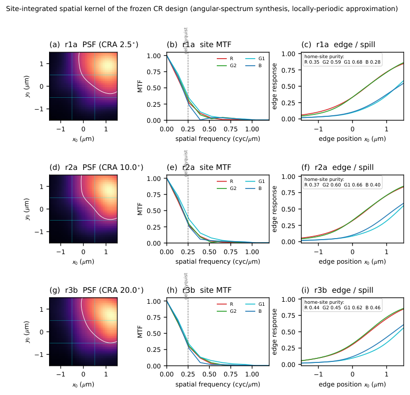
S7 The plane-wave control
Under a single normal-incidence plane wave – the input the CR literature optimizes against – every configuration tried here clears the CFA, and the constraints usually imposed for convenience change only by how much (Fig. S9).
The two runs are matched in seed, total silicon nitride thickness (), projection sharpness and optimizer settings, and differ only in the constraint placed on the pattern, so what separates them is freedom rather than volume.

The mirror caps the channel count.
A mirror maps the two middle wells onto each other, so their spectra are forced to coincide. The cell has four wells, but a mirrored design therefore carries only three independent spectral channels: the four well responses span a rank-three measurement space, so one measurement degree of freedom is unavailable to the imaging information of Sec. S3. Releasing the mirror recovers it and is worth bit per raw pixel here.
The mirror is also inconsistent with the deployment geometry: no design slot except the near-axial one has a ray ensemble even approximately invariant under , and that slot carries the smallest field weight.
Numerical caveat at increased thickness.
The twinned-well agreement in a mirrored design is a direct probe of the forward solver’s own symmetry error, because the mask is exactly symmetric by construction. That error is at and at in the same complex-single-precision solve. It remains two orders of magnitude below the differences reported above, but it grows steeply with thickness.
S8 The design method
The optimized variable is a latent field, bilinearly upscaled to the permittivity grid, passed through a conic filter of radius nm and a tanh projection in the robust erosion/dilation formulation of the main text. The free parameters number against the of the raster, and the minimum feature follows from the parameterization rather than from the filter alone.
The forward pass is straight-through: the thresholded binary mask is what the solver sees and what is scored, while the gradient is taken through the relaxed density. The two differ: at the lowest projection sharpness the relaxed density scores bit below the mask that is scored, so the projection sharpness follows a schedule from to over the run rather than being held at its lowest value. Gradients are taken by reverse-mode differentiation through the solver, and the latent is updated by Adam at a learning rate of for to steps.
Adam proposes each step, and an exact hard-mask evaluation admits it only if the hard mask it produces scores above the accepted one under the search quadrature; otherwise the latent and the optimizer moments revert to the accepted state and the learning rate is halved, recovering on the next acceptance. The reported trajectory is therefore monotone by construction (Fig. S10). Acceptance is tested every fourth step, so the search between tests is unconstrained. Runs are warm-started from an existing mask, whose latent is recovered by fitting the coarse field to the target pattern before the run begins. A restart from a converged design gained nothing, which is how the reported values were taken to be converged rather than truncated.
Search uses the eight-ray reduction and every reported value the sixteen-ray rule; the eight-ray figures quoted in this section are search proxies.

S9 Terms of the comparison
The CFA reference is a spectral transmittance calculation and does not propagate through the CR-to-detector gap. That asymmetry is physical rather than procedural: a dye CFA sits in contact with the pixel, so the gap, and the walk-off it causes, is a cost the CR architecture incurs and the CFA does not.
The same comparison run at the nominal exposure rather than below the crossing reverses (Fig. S11), which is the other half of the main text’s exposure scan seen in a recovered image.
The CFA collects of the light incident on a pixel, against for the CR, so the comparison already grants the CR a advantage in optical power, after quantum-efficiency weighting, and it still loses at the nominal exposure. Adding uniform inter-well mixing to the filter-array response to represent an imperfect real CFA leaves the ordering intact: at five, ten and twenty percent mixing the reference falls to , and bit per raw pixel, all above the CR’s .
Replacing the three-dimensional XYZ target with the scene’s own leading spectral modes does not reverse the ordering at any rank between three and eight; the gap narrows when the target is matched in dimension to the scene rather than to the eye, which quantifies how much of the CFA’s advantage is the alignment of dye transmittances with the color-matching functions, but it does not cross zero.
S10 The paired-source control
The main-text ranking evidence re-scores finished designs; a stronger control optimizes under each source. From a single cold initialization the search is run twice with the recipe of Sec. S8 unchanged except for the illumination it optimizes against—the slot’s eight-ray pupil ensemble at its chief ray, against a single normal plane wave—and both designs are scored under the one sixteen-ray pupil evaluation the paper reports its numbers with. The pupil-source design scores higher on both seeds tried, by and bit per raw pixel (Fig. S12). The direction is consistent while the magnitude is seed-dependent at this sample size; the control isolates the source from the initialization, so the source changes which design the search reaches and not merely how finished designs are ranked.