A High-Order Flux Reconstruction Actuator-Line Framework for Rotating-Blade Aerodynamics on Fixed Cartesian Grids
Abstract
This work couples a high-order flux reconstruction/correction procedure via reconstruction (FR/CPR) solver with a rotating actuator-line model (ALM) to simulate rotating-blade aerodynamics on fixed Cartesian grids. Blade loading is represented by volumetric body force source terms projected through an isotropic Gaussian kernel in a blade-attached frame, eliminating the need to resolve blade geometry. Vertical-axis wind turbines (VAWTs) serve as the demonstration configuration, with a modified Boeing-Vertol dynamic stall model incorporated to capture unsteady lift and drag. A mesh-resolution criterion for the Gaussian projection kernel on reasonably coarse meshes is derived. It shows that cost-effective coarse meshes can operate in a mesh-controlled regime with negligible induction feedback, motivating a Double Multiple Streamtube (DMST) correction to recover the physical inflow. Simulations are carried out over a range of tip-speed ratios at a chord-based Reynolds number of . The framework is validated against experimental near-wake measurements and previously reported LES-ALM results, and the mean wake profile shows good agreement. The predicted power-coefficient curve matches high-fidelity three-dimensional LES-ALM data to within around the optimal VAWT operation conditions. The framework also captures the regime-dependent influence of dynamic stall, azimuthal blade loading, lift hysteresis, and characteristic wake structures. These results demonstrate that the FR/CPR-ALM framework provides an accurate and computationally efficient geometry-free approach for VAWT analysis, making it well suited for parametric studies and large-scale wind energy applications.
I Introduction
The growing demand for sustainable energy and the need to reduce greenhouse gas emissions have accelerated the development of renewable power technologies. Among these, wind energy has become one of the most fastest-growing sources of clean electricity worldwide. Continuous improvements in aerodynamic modeling and computational methods have been central to this progress, raising both turbine efficiency and reliability. Vertical-axis wind turbines (VAWTs) have drawn renewed interest for their geometric simplicity, omni-directional operation, and suitability for urban and offshore installations 21; 27; 47. Unlike horizontal-axis turbines, VAWTs need no yaw control and operate effectively in turbulent, highly sheared inflow. A comprehensive aerodynamic treatment of these machines is given in the classical monograph by Paraschivoiu 34. Despite these advantages, predicting VAWT performance accurately remains difficult because of the strong unsteady blade loading and the complex wake interactions involved. The aerodynamics of straight-bladed VAWTs differ fundamentally from steady airfoil behavior. During a single revolution, each blade sees a continuously varying angle of attack set by the combination of freestream velocity and rotational motion. At low tip-speed ratios, this variation often produces dynamic stall, vortex shedding, and delayed flow reattachment 30; 24. Dynamic stall has been studied extensively for oscillating airfoils and rotorcraft 25, and similar mechanisms govern VAWT blade aerodynamics 39. The unsteady vortex formation in the upwind region, together with the subsequent blade-wake interaction on the downwind pass, strongly affects torque production and efficiency.
High-fidelity CFD has been widely used to analyze VAWT aerodynamics because it resolves the unsteady blade loading and the evolution of the near wake over many revolutions. For straight-bladed turbines, the unsteady Reynolds-averaged Navier-Stokes (URANS) model with sliding meshes is a common choice, since it captures the periodic variation of angle of attack and the associated load hysteresis at moderate cost. Early URANS studies examined how different turbulence closures affect the reproduction of dynamic-stall-driven load loops on H-type Darrieus rotors 39. Practical 2D CFD workflows for H-Darrieus turbines have also been developed to reproduce overall performance trends. These studies emphasize that predicted power and peak loads are sensitive to numerical resolution and to unsteady setup choices, such as the azimuthal step and the number of revolutions needed for statistical convergence 23. URANS can over-diffuse the vortex-dominated physics and wake turbulence, motivating the exploration of higher-fidelity simulation approaches. Among these include the so-called 2.5D large eddy simulation (LES) configurations, which keep the cost low while improving the representation of high-angle-of-attack flow and stall-related vortex shedding. In regimes where separation and dynamic stall dominate, comparative studies report that 2.5D LES is more accurate than purely 2D URANS 26. Experimental wake data remain essential for assessing these predictions, and detailed near-wake datasets from stereoscopic PIV have become standard benchmarks for validating VAWT wake simulations 41. Blade-resolved URANS and LES offer clear physical insight, but they stay expensive when many revolutions are needed for converged phase-averaged statistics. This motivates reduced-order, actuator-based representations for performance and wake studies.
To lower computational expense while retaining the essential aerodynamic physics, actuator-based representations have been adopted for VAWT simulations. The actuator disk model (ADM) and actuator line model (ALM) replace the explicit blade geometry with distributed body forces, which reduces grid requirements substantially relative to blade-resolved CFD 40; 32; 42. For VAWTs, experimental performance and near-wake measurements at moderate Reynolds numbers have provided important validation targets for these reduced-order models, particularly for torque production and wake recovery 2. The Reynolds number dependence of cross-flow turbine performance and wake structure was examined later, and both the power coefficient and the near-wake structure were found to depend on the operating Reynolds number 3. Accurate force prediction in actuator-based models depends strongly on the quality of the airfoil data. The classical Sandia measurements by Sheldahl and Klimas remain a common source, providing lift and drag coefficients for symmetrical airfoils across wide ranges of Reynolds number and angle of attack, and these data are widely used in VAWT simulations 37. Beyond force data, LES has been used to study VAWT wake development in atmospheric boundary layers, where coherent vortex shedding interacts with the background turbulence 36. Direct comparisons between simulation and experiment show that two-dimensional CFD reproduces general performance trends but tends to underpredict three-dimensional wake effects and dynamic stall features 6. The actuator line theory has also been adapted specifically for VAWT configurations, and with careful selection of kernel width and projection strategy it can reasonably represent rotating blade kinematics and improve wake prediction 31. Adding a dynamic stall correction within actuator-based frameworks further improves phase-dependent load prediction, particularly where the angle of attack varies rapidly 15. More recent LES studies of helical and straight-bladed vertical-axis turbines in boundary-layer inflow show how blade geometry and turbulence structure shape wake evolution and performance 11. Together these studies establish the promise of actuator-based modeling combined with turbulence-resolving simulation, though they still leave open the challenge of balancing numerical accuracy, computational efficiency, and a robust treatment of unsteady aerodynamic effects.
In parallel with these advances in actuator modeling, high-order numerical methods have drawn increasing attention as alternatives to traditional second-order finite-volume schemes. Discontinuous Galerkin (DG) methods 7; 5; 14 and flux reconstruction/correction procedure via reconstruction (FR/CPR) approaches 16; 45; 43 deliver higher accuracy per degree of freedom and lower numerical dissipation than low-order discretizations. These properties are especially attractive for wind turbine simulations, where preserving coherent vortical structures and minimizing artificial wake diffusion are essential. High-order DG formulations have been applied to LES of wind turbine wakes, with improved resolution of near-wake vortex dynamics and turbulence structures 9. Spectral element methods have similarly reduced dispersion error and preserved wakes more faithfully 22. More recently, high-order FR-based LES has been used to study wind turbine aerodynamics in both ducted and open-rotor configurations, reporting better wake recovery and performance prediction than lower-order schemes 8. ALM has also been integrated within high-order solvers, where increasing the polynomial order sharpens wake resolution without a proportional increase in mesh density 29; 33; 1. These developments show that high-order frameworks suit turbine-induced, vortex-dominated flows well. Yet progress has centered on horizontal-axis configurations, and applications to rotating vertical-axis turbines remain comparatively limited. In particular, the coupling of FR/CPR formulations with actuator-line representations for straight-bladed VAWTs, especially in dynamic-stall-dominated regimes, has not been systematically examined.
Building on previously developed high-order source-term frameworks for wind energy applications 18; 19; 20, the present study advances the methodology from steady ADM representations to a fully rotating ALM within a time-accurate FR/CPR solver. Previous studies demonstrated that regularized source terms accurately reproduce steady and unsteady flow features on fixed Cartesian grids and capture mean wake characteristics using ADM 19; 18. However, ADM cannot resolve azimuthally varying blade loads, dynamic stall, or the wake asymmetry of rotating VAWTs. The present work addresses these limitations by introducing a rotating ALM coupled with isotropic Gaussian force projection and a semi-empirical dynamic stall correction within the high-order FR/CPR framework. This extension enables time-resolved blade motion, physically consistent angle-of-attack evolution, and unsteady force generation, while maintaining the advantages of a fixed-grid high-order discretization. The resulting framework bridges validated static source-term methods and fully time-dependent ALM, and establishes a foundation for accurate, computationally efficient simulation of vortex-dominated turbine flows.
The remainder of the paper is organized as follows. Section II describes the numerical formulation, including the FR/CPR discretization, the actuator-line implementation, and the coupling between them. Section III presents verification, validation, and flow-field analysis. Finally, Section IV concludes this work.
II Methodology
II.1 FR/CPR discretization
The flow governed by the two-dimensional compressible Navier-Stokes equations can be written in conservative form as
| (1) |
where is the vector of conserved variables, and are flux vectors in the - and -direction, and is the source vector. The vector of conserved variables is defined as
| (2) |
In this notation, is the density, are the Cartesian velocity components, and is the total energy per unit volume. Closure for a perfect gas is provided by
| (3) |
where is the ratio of specific heats.
Each flux is split into an inviscid and a viscous contribution,
| (4) |
The inviscid parts carry the convective transport and the pressure work,
| (5) |
while the viscous parts follow a Newtonian stress closure together with Fourier heat conduction. The stress components are
| (6) | ||||
| (7) | ||||
| (8) |
and the heat fluxes are
| (9) |
where is the temperature, is the dynamic viscosity, is the specific heat at constant pressure, and is the Prandtl number.
The FR/CPR discretization is built on a reference element rather than on the physical mesh directly. The physical domain is first covered by a set of non-overlapping quadrilateral elements , i.e. , where is the number of elements. Every element is then mapped onto the standard square . As a result, all operations are carried out on a single fixed reference geometry. Under this mapping the governing system keeps its conservative structure and becomes
| (10) |
where the transformed state is scaled by the mapping Jacobian,
| (11) |
and is the Jacobian determinant. The transformed fluxes gather the physical fluxes weighted by the metric terms,
| (12) | ||||
| (13) |
The metric terms in Eqs. (12) and (13) come from the coordinate transformation. For a general time-independent mapping , the Jacobian matrix and its determinant are
| (14) |
with
| (15) |
The inverse mapping supplies the metric coefficients,
| (16) |
Within each reference element the solution is represented by a tensor-product polynomial of degree in and . Using a nodal Lagrange basis, the transformed state is expanded as
| (17) |
where the are Lagrange polynomials tied to solution points. Gauss–Legendre points are used for these nodes, since they combine accurate quadrature with numerical stability. Their layout, together with the flux points introduced below, is shown in Fig. 2.
The fluxes are first sampled at the solution points, which gives an element-local flux polynomial in each direction,
| (18) | ||||
| (19) |
with and defined in Eqs. (12) and (13). Because each element is treated independently, these local polynomials are generally discontinuous at element interfaces and cannot enforce conservation on their own.
Conservation and interelement coupling are restored through a common interface flux. Left and right states are reconstructed at a set of flux points on the element boundaries, and a single-valued flux is then formed from the two sides. For the inviscid part, a Roe-type approximate Riemann solver provides the common flux 35, while the common viscous flux is evaluated with the second approach of Bassi and Rebay (BR2) 4. The gap between the local flux and this common flux at the boundaries is redistributed into the element interior by correction functions. As a result, the corrected polynomials read
| (20) | ||||
| (21) |
The corrections and are chosen so that the corrected flux polynomials reproduce the common fluxes exactly at the element boundaries. Radau polynomials are adopted for this purpose, a choice that recovers the DG scheme within the FR/CPR family 16.
Differentiating the corrected fluxes and inserting them into Eq. (10) produces the semi-discrete update at each solution point,
| (22) |
This can be rewritten in a general form as
| (23) |
where is the spatial residual. Equation (23) is advanced in time with the explicit strong-stability-preserving Runge–Kutta (SSP-RK) scheme 38, which retains the stability of the spatial operator and is well suited to hyperbolic systems. The three-stage form used here advances the solution as
| (24) |
II.2 Actuator line model for vertical-axis wind turbines
The ALM method extends the classical theory of blade elements by representing turbine blades as rotating lifting lines embedded within the flow field 40.
In a two-dimensional formulation, each blade is modeled using a single actuator point, representing a spanwise-uniform blade element. This differs from conventional three-dimensional ALM approaches, where multiple elements are distributed along the blade span. The resulting forces are introduced into the momentum equations as volumetric source terms and are computed from local blade-element aerodynamics. The source vector given in Eq. (1) is then replaced with the blade-induced forcing through volumetric source terms. The resulting system can be written as
| (25) |
where represents the actuator-line source vector written as
| (26) |
Herein, and are the body forces acting on fluids in the - and -direction, respectively, and is the resulting work on fluids.
Consider a horizontal cross-section of a blade rotating with angular velocity at a fixed radius from the rotor center, shown in Fig. 3. The incoming flow is a uniform freestream , and the azimuthal angle is measured counter-clockwise from the axis. Because the blade extracts momentum from the flow, the velocity it experiences is the reduced local inflow, denoted in the upwind half and in the downwind half following the induction model of Sec. III.4.2. At each actuator point, a local frame is defined by the normal radially outward and the tangent , which points in the direction of blade motion. The section travels at velocity , so the relative velocity experienced by the blade is
| (27) |
where is the local inflow at the actuator point, equal to or depending on the azimuthal half. Projecting onto the local frame gives the chord-normal and chord-tangential components and , from which the angle of attack is
| (28) |
The four-quadrant form, together with the chord convention , resolves over the full range of incidence swept in one revolution.
For a vertical-axis turbine the incidence changes large and rapidly over one revolution, and at low to moderate tip-speed ratios the blade passes well beyond static stall. This drives dynamic stall 30, marked by delayed separation and hysteresis in the aerodynamic loads. A modified Boeing-Vertol model 13 corrects the quasi-steady coefficients. The rate of change of incidence is evaluated once per physical time step by a backward difference,
| (29) |
The corrected incidences for lift and drag are
| (30) | ||||
| (31) |
with empirical coefficients
| (32) |
where is the thickness ratio, equal to for the NACA 0018 section used here, giving and . For the symmetric airfoil the zero-lift angle is . The corrected coefficients are
| (33) |
with and from tabulated static polars. When falls below a small threshold the ratio is bypassed and is used, which removes the singularity as . This construction preserves the static polar under quasi-steady conditions and introduces rate-dependent hysteresis through during the rapid incidence changes typical of VAWT operation.
The sectional lift and drag magnitudes are
| (34) |
and act along the wind-aligned unit vectors and . Therefore, the aerodynamic force on the blade, per unit span, is
| (35) |
For diagnostics and torque the same force is written through its tangential and normal components,
| (36) |
with positive in the power-generating direction. The per-blade contribution to rotor torque is .
The discrete blade forces are returned to the flow as smooth volumetric source terms, which limits numerical stiffness and reduces sensitivity to the local mesh spacing. The present implementation uses an isotropic Gaussian kernel centered on each blade. For a point with displacement from blade , the kernel is
| (37) |
which integrates to unity over . The width is set by the larger value of a mesh measure and a chord measure,
| (38) |
where is the local element size, the solution polynomial degree, and a chord-fraction constant, set to in all simulations reported here. The mesh term keeps the kernel resolvable on the grid, while the chord floor prevents the support from shrinking below the blade scale. For efficiency the kernel support is truncated at .
By Newton’s third law the force on the fluid is equal and opposite to the aerodynamic force on each blade. Summing the kernel-weighted reaction of every blade gives the source term vector,
| (39) |
where and are the components of the aerodynamic force on blade from Eq. (35), and is the corresponding rate of work done on the fluid. The momentum and energy forcing share the same projection and are therefore consistent by construction.
The instantaneous aerodynamic torque about the rotation axis (per unit span) and the mechanical power are computed as
| (40) |
where is the blade position vector in the rotor plane. For the two-dimensional simulations reported herein, the reference swept area per unit span is , corresponding to the projected frontal area per unit span. The power coefficient is then expressed as
| (41) |
In the FR/CPR framework, Eq. (39) are evaluated at the element quadrature points and assembled into the semi-discrete residual as volumetric forcing terms. The isotropic smoothing in Eq. (37), with the grid-dependent width in Eq. (38), gives stable time integration and preserves the rotor-induced momentum deficit and wake development across the mesh resolutions considered. It should be noted that the present ALM formulation is implemented in a two-dimensional framework, where each blade is represented by a single actuator point corresponding to its cross-section. This differs from conventional three-dimensional ALM approaches, where blades are discretized into multiple spanwise elements. The present formulation can be extended to three-dimensional configurations in a straightforward manner.
III Results and Discussions
III.1 Numerical setup
We perform all simulations using a high-order FR/CPR solver coupled with the ALM on fixed, structured Cartesian meshes. The computational domain is a two-dimensional rectangular region defined by , where denotes the rotor diameter. The turbine is located at the domain center and is represented solely through volumetric ALM forcing. A uniform freestream velocity is prescribed at the inlet, a zero-gradient condition is applied at the outlet, and slip conditions are imposed on the top and bottom boundaries. The domain size is chosen so that the near-wake region is not influenced by the outer boundaries.
To accurately capture the actuator forcing and near-wake dynamics, we introduce a locally refined rectangular region around the turbine spanning and . Outside this region the mesh is gradually coarsened toward the far-field boundaries to reduce computational cost. Figure 4 shows the overall mesh and a zoomed view of the refined turbine region; the rotor location is indicated by a circle for reference only, as no physical blade geometry is present.

(a) Full computational domain

(b) Zoomed view of the turbine-center region
The solution is advanced from a uniform freestream initial condition with a constant time step , and time-averaged statistics are collected after a statistically periodic state is reached, typically within - rotor revolutions. Blade aerodynamic coefficients are obtained from tabulated static data 37 and corrected for unsteady effects using the Boeing-Vertol dynamic stall model (Sec. II.2). Induction is accounted for through a Double Multiple Streamtube (DMST) correction as explained in Sec. III.4.
III.2 Model validation
The present FR/CPR-ALM framework is validated against the experimental near-wake measurements of Bachant and Wosnik 2 and the ALM-LES results of Hezaveh et al. 15. The reference configuration is a three-bladed vertical-axis turbine of diameter with chord , operating at a freestream velocity of and a turbine Reynolds number . The solidity is defined here as . The validation is carried out at , the tip-speed ratio at which Bachant and Wosnik report near-wake measurements.

We consider three levels of grid resolution to assess the sensitivity of the FR/CPR-ALM framework to spatial discretization. The inner refined region is discretized using , , and elements, corresponding to approximately k, k, and k total cells, respectively. Figure 5 compares the normalized mean streamwise velocity at for the three mesh levels against the experimental and ALM-LES reference data. All three numerical solutions reproduce the principal features of the near wake, namely the magnitude and lateral extent of the centreline velocity deficit and the transverse asymmetry induced by rotor rotation. Relative to the experiment and 3D LES results, the two-dimensional formulation tends to overpredict the depth of the velocity deficit, consistent with the absence of three-dimensional spanwise momentum transport. Since the results from the three sets of meshes agree reasonably well with each other (except in the region ), the coarse mesh is selected to save computational cost.
III.3 Gaussian kernel resolution criterion
Self-consistent actuator-line coupling requires the Gaussian width to be governed by the chord rather than by the local mesh spacing. With the isotropic width of Eq. (38), , the kernel is chord-controlled when the chord floor exceeds the mesh term, . This gives the resolution criterion
| (42) |
For the present geometry (, , ), Eq. (42) requires . Table 1 lists the kernel width and its controlling factor for each mesh level.
| Mesh | Cells | (m) | (m) | (m) | Regime |
|---|---|---|---|---|---|
| Coarse () | 29k | 0.065 | 0.022 | 0.043 | Mesh |
| Medium () | 62k | 0.045 | 0.015 | 0.033 | Chord |
| Fine () | 129k | 0.032 | 0.011 | 0.033 | Chord |
On the coarse mesh used for the production runs, the mesh term governs. Therefore, the kernel is mesh-controlled and its support is set by the grid rather than the chord. On the finer meshes the width settles to the chord floor . In either regime the support radius spans roughly one chord or more, so the blade force is smeared over a region large compared with the blade itself and the induced velocity perturbation sampled at the actuator point is strongly diluted. Self-consistent induction feedback from the resolved field would require a substantially finer mesh than is practical for a parametric tip-speed-ratio sweep, which motivates the explicit induction treatment introduced in Sec. III.4.
III.4 Power coefficient and induction modeling
The power coefficient as a function of tip-speed ratio is the primary performance metric of the turbine. Its accurate prediction requires both physically consistent blade loading, supplied by the FR/CPR-ALM with Boeing-Vertol correction and a physically correct effective inflow velocity at the blade.
III.4.1 Motivation for an explicit induction model
In an ALM the blade forces are computed from the local fluid velocity at the actuator point, which ideally reflects the rotor-induced deceleration of the inflow responsible for the existence of an optimal tip-speed ratio. In the present framework this velocity is sampled from the FR/CPR solution by high-order Lagrange interpolation (Sec. II.2). However, we found that direct sampling of the resolved velocity field at the blade yields a power coefficient curve nearly coincident with the zero-induction result. We note that self-consistent feedback would require a substantially finer mesh than is practical for a parametric tip-speed-ratio sweep. Therefore, induction is modeled explicitly through DMST correction to enable reliable simulations with reasonably coarse meshes.
III.4.2 Double multiple streamtube induction correction
The DMST model 34 divides the rotor disk into an upwind half cycle () and a downwind half cycle (), each treated as an actuator disk. The effective inflow velocity in each half cycle is
| (43) | ||||
| (44) |
where the Rankine-Froude momentum theorem gives the downwind condition as twice the upwind induction at the disk plane. The upwind induction factor is obtained from the rotor thrust coefficient via momentum theory with the Glauert correction for heavily loaded rotors 12:
| (45) |
The factor is updated once per rotor revolution from the time-averaged of the preceding revolution, with under-relaxation to suppress oscillations at high tip-speed ratios:
| (46) |
Starting from , the induction factor converges to a stationary value within approximately ten revolutions at all tip-speed ratios considered.
III.4.3 Power coefficient curve
Figure 6 presents the time-averaged power coefficient as a function of tip-speed ratio obtained with the DMST induction correction and the Boeing-Vertol dynamic stall model, together with the 3D LES-ALM results of Shamsoddin and Porté-Agel 36 as a high-fidelity reference. Each point is averaged over the final of a run.
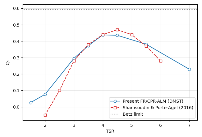
The power coefficient rises from at to a peak of at , then declines to at , which reproduces the characteristic single-peaked behaviour of a vertical-axis turbine. The peak value lies within of the reference peak of , and the two curves closely follow each other over the range - that brackets the optimum. The present peak occurs at rather than the reference value of predicted by the 3D LES-ALM simulation.
At low tip-speed ratios () the present results lie above the 3D reference. This agrees with the observation of Liu et al. 27, who found that the power coefficients predicted at low tip-speed ratios by two-dimensional simulations are much larger than those predicted by three-dimensional simulations. The discrepancy is most pronounced in the stall-dominated regime and diminishes toward the optimum, where the flow remains largely attached and two- and three-dimensional predictions converge. Table 2 summarizes the results. The standard deviation is largest at low tip-speed ratios, where the strong cyclic loading of dynamic stall dominates, and smallest near the optimum, where the loading is smooth.
| Revolutions | (3D LES-ALM) | |||
|---|---|---|---|---|
| 1.5 | 0.027 | 0.027 | 7.2 | – |
| 2.0 | 0.075 | 0.078 | 9.5 | |
| 3.0 | 0.296 | 0.137 | 14.3 | 0.28 |
| 3.5 | 0.376 | 0.128 | 16.7 | 0.38 |
| 4.0 | 0.443 | 0.072 | 19.1 | 0.44 |
| 4.5 | 0.439 | 0.073 | 21.5 | 0.47 |
| 5.5 | 0.382 | 0.077 | 26.3 | 0.37 |
| 7.0 | 0.229 | 0.089 | 33.4 | – |
III.5 Effect of the Boeing-Vertol dynamic stall correction
The influence of the Boeing-Vertol correction is isolated by comparing simulations that use the static airfoil polar directly against those that apply the dynamic stall model, at two representative tip-speed ratios, i.e. and . At the blade operates deep in dynamic stall, and at the oscillations are milder. The corresponding angle-of-attack histories are documented in Sec. III.6.1.
III.5.1 Lift hysteresis
Figure 7 shows the phase-averaged trajectory over one rotor revolution at the two tip-speed ratios. The static polar is traced reversibly as the angle of attack increases and decreases, whereas the Boeing-Vertol result forms a hysteresis loop characteristic of dynamic stall.
At the angle of attack reaches approximately , far beyond the static stall angle, and the dynamic stall loop is correspondingly large. On the upstroke the correction delays separation and sustains lift well above the static maximum, and the modified incidence drives the lift coefficient to its imposed ceiling near the peak of the excursion. On the downstroke the lift recovers along a markedly lower branch. The enclosed area of the loop, a measure of the unsteady energy exchange, is substantial at this condition. At the angle of attack remains within to , near or below the static stall angle, and the loop is correspondingly thin. The Boeing-Vertol and static curves nearly coincide, with only a slight overshoot on the upstroke. This contrast confirms that the correction is active where it is physically warranted and essentially dormant where the flow remains attached.

III.5.2 Tangential force and torque
The aerodynamic consequence of the lift hysteresis appears directly in the tangential force shown in Fig. 8, which governs the instantaneous torque. At the Boeing-Vertol correction raises the peak tangential force in the upwind pass to roughly , compared with about for the static polar, and introduces additional structure associated with the delayed-stall vortex dynamics, including a secondary peak in the downwind pass near . The corrected loading also shows regions of negative over part of the cycle, which reflects the deep-stall excursions. At the loading is organized into two clean lobes corresponding to the upwind and downwind passes. The Boeing-Vertol peak in the upwind pass () exceeds the static value (), consistent with the modest upstroke overshoot seen in the lift hysteresis. The higher peak is offset by lower loading over the remainder of the cycle. Therefore, the cycle-averaged torque falls below the static value, as quantified in Sec. III.5.3.

III.5.3 Effect on power coefficient
Table 3 quantifies the net effect of the correction on the time-averaged power coefficient at three tip-speed ratios spanning the deep-stall, light-stall, and attached regimes. The sign of the effect varies with operating condition. At the correction increases by , since delaying separation recovers tangential force during the power-generating portion of the deep-stall cycle. At it decreases by , which removes the over-prediction that the static polar produces in light stall. At , where the flow is largely attached, the effect is small () and reflects only the mild unsteady hysteresis. These results show that dynamic stall modeling is not a uniform correction but a regime-dependent one, and that it is essential for predicting blade loading across the full range of VAWT operating conditions.
| (static) | (Boeing-Vertol) | Change (%) | ||
|---|---|---|---|---|
| 1.5 | 0.0217 | 0.0267 | ||
| 3.5 | 0.4212 | 0.3761 | ||
| 5.5 | 0.3568 | 0.3815 |
III.6 Blade kinematics and flow field
III.6.1 Angle of attack and its rate
Figure 9 shows the phase-averaged angle of attack and its rate of change as functions of rotor azimuth for and . The amplitude of decreases sharply with increasing tip-speed ratio. At the blade sweeps from approximately in the upwind pass to in the downwind pass, which places it deep into stall on both halves of the revolution, whereas at the excursion is confined to roughly , near the static stall boundary. This reduction follows directly from the velocity triangle, in which the rotational contribution grows relative to the freestream as increases and diminishes the variation of incidence.
The rate of change in Fig. 9b peaks near , where the blade transitions between the upwind and downwind passes. The peak rate reaches approximately at , more than double the value at , which is consistent with the larger and more rapid incidence variation that drives the strong dynamic stall at low tip-speed ratio. The small discontinuity in near corresponds to the upwind-to-downwind transition of the DMST induction model, across which the effective inflow velocity changes between the two streamtube halves.

(a) Angle of attack,

(b) Rate of change,
III.6.2 Instantaneous velocity and vorticity
Figures 10 and 11 show the instantaneous streamwise velocity and spanwise vorticity at for and . The two operating conditions produce qualitatively different wakes. At the deep-stall excursions documented in Sec. III.6.1 shed large discrete vortices on each blade passage, which produces a broad, energetic wake in which coherent vortical structures spread over a wide lateral extent and the freestream penetrates between successive vortices. At , where the flow remains largely attached, the shed vorticity is finer and more regularly organized into two shear layers that bound a deeper central velocity deficit, and the wake stays coherent further downstream.
Figure 12 shows the corresponding momentum source terms and at , which confirm that the Gaussian forcing is localized at the instantaneous blade positions along the rotor circle.

(a)

(b)

(a)

(b)

(a)

(b)
III.6.3 Time-averaged wake
Figures 13 and 14 show the time-averaged streamwise velocity and spanwise vorticity fields. Although the instantaneous wake is far more energetic at , the mean velocity deficit is comparatively shallow there, consistent with the low net power extraction at this condition (). The large discrete vortices redistribute momentum without producing a deep sustained deficit, so the mean field shows a broad wake with diffuse shear layers. At , by contrast, the mean deficit is markedly deeper and more elongated, which reflects the much higher power extraction (), and the mean vorticity concentrates in two thin, persistent shear layers that bound the wake far downstream. The contrast between the two conditions shows that strong instantaneous unsteadiness and large mean momentum extraction are distinct. The deep-stall regime is unsteady but extracts little net power, whereas the near-optimal regime is comparatively smooth yet produces the deepest mean wake.

(a)

(b)

(a)

(b)
III.7 Computational efficiency
Take a representative case at as an example. It only requires about minutes of wall-clock time on CPU cores (or roughly one minute per revolution) to advance the flow field to of physical time ( rotor revolutions). This rapid turnaround makes parametric tip-speed-ratio sweeps practical. However, we mention that the efficiency comes at the cost of near-wall fidelity, since body-fitted methods resolve the blade boundary layer directly and predict drag-sensitive quantities such as separation onset and total pressure loss more accurately than the present approach. The framework is therefore best suited for the rapid prediction of wake dynamics and overall rotor performance during the VAWT design process or for VAWT farm optimization.
IV Conclusion
A high-order FR/CPR solver has been coupled with a rotating actuator-line model to simulate rotating-blade aerodynamics on fixed Cartesian grids, with a straight-bladed vertical-axis wind turbine as the demonstration configuration. The formulation combines a compressible Navier-Stokes framework with a volumetric body-force representation of blade loading, an isotropic Gaussian projection in a blade-attached frame, and a modified Boeing-Vertol dynamic stall model that accounts for the strongly unsteady aerodynamics inherent to vertical-axis turbine operation.
The approach was assessed through grid-independence and validation studies. The mean near-wake profile was shown to be in reasonably good agreement with experimental measurements and previously published LES-ALM results, matching both the magnitude and the lateral extent of the velocity deficit. A resolution criterion for the Gaussian projection kernel was derived, which shows that on coarse meshes the kernel is mesh-controlled, and that even where it becomes chord-controlled on finer grids its support still spans about one chord. In both regimes the resolved velocity field supplies negligible induction feedback, which motivated an explicit Double Multiple Streamtube correction. With this correction the predicted power-coefficient curve agrees with high-fidelity three-dimensional LES-ALM data to within around the optimal turbine operation conditions.
The framework reproduces the key aerodynamic features of vertical-axis turbine operation. The strong azimuthal variation of blade loading and the associated lift hysteresis are captured, and the Boeing-Vertol correction acts in a regime-dependent manner. It increases the power coefficient in deep stall by delaying separation, and reduces it in light stall by removing the over-prediction of the static polar. Instantaneous and time-averaged flow fields show that the deep-stall regime is highly unsteady yet extracts little net power and leaves a broad but shallow mean wake, whereas the near-optimal regime is comparatively smooth yet produces the deepest mean momentum deficit.
Overall, the FR/CPR-ALM framework provides a computationally efficient and geometry-free tool for rotating-blade aerodynamics that needs neither body-fitted meshes nor sliding-mesh treatment. Its principal advantage lies in mesh-free setup and high accuracy per degree of freedom rather than in raw per-revolution cost, for which it is comparable to body-fitted 2D URANS. The method suits parametric studies and provides a foundation for extensions to three-dimensional effects, multi-turbine interactions, and rotor optimization, as well as other rotating- and fixed-blade applications.
Acknowledgments
Part of the hardware used in the computational studies is from the UMBC High Performance Computing Facility (HPCF). The facility is supported by the U.S. National Science Foundation through the MRI program (grant nos. CNS-0821258, CNS-1228778, OAC-1726023, and CNS-1920079) and the SCREMS program (grant no. DMS-0821311), with additional substantial support from the University of Maryland, Baltimore County (UMBC).
References
- Wind turbine aerodynamics simulation using the spectral/ element framework (nektar++) with an actuator line model. Engineering Proceedings 5 (1), pp. 6. External Links: Link Cited by: §I.
- Performance and near-wake measurements for a vertical axis turbine at moderate reynolds number. In Fluids Engineering Division Summer Meeting, Vol. 55553, pp. V01BT12A005. External Links: Document Cited by: §I, Figure 5, §III.2.
- Reynolds number dependence of cross-flow turbine performance and near-wake characteristics. Cited by: §I.
- Discontinuous galerkin solution of the reynolds-averaged navier–stokes and k– turbulence model equations. Computers & Fluids 34 (4), pp. 507–540. Cited by: §II.1.
- A high-order accurate discontinuous finite element method for the numerical solution of the compressible navier–stokes equations. Journal of computational physics 131 (2), pp. 267–279. External Links: Document, Link Cited by: §I.
- Effectiveness of two-dimensional cfd simulations for darrieus vawts: a combined numerical and experimental assessment. Energy Conversion and Management 136, pp. 318–328. Cited by: §I.
- TVB Runge–Kutta local projection discontinuous Galerkin finite element method for conservation laws II: general framework. Mathematics of Computation 52, pp. 411–435. External Links: Document, Link Cited by: §I.
- High-order large eddy simulations of a wind turbine in ducted and open-rotor configurations. Journal of Fluids Engineering 145 (2), pp. 021201. External Links: Document Cited by: §I.
- Discontinuous galerkin methodology for large-eddy simulation of wind turbine wakes. In Journal of Physics: Conference Series, Vol. 753, pp. 022037. External Links: Document, Link Cited by: §I.
- The efficiency of a turbine in a tidal channel. Journal of Fluid Mechanics 588, pp. 243–251.
- Large-eddy simulation of helical-and straight-bladed vertical-axis wind turbines in boundary layer turbulence. Journal of Renewable and Sustainable Energy 14 (5). Cited by: §I.
- Airplane propellers. In Aerodynamic Theory, W. F. Durand (Ed.), Vol. IV. Cited by: §III.4.2.
- A mathematical model of unsteady aerodynamics and radial flow for application to helicopter rotors. Technical report Cited by: §II.2.
- Nodal discontinuous galerkin methods. Springer. Cited by: §I.
- Simulation and wake analysis of a single vertical axis wind turbine. Wind Energy 20 (4), pp. 713–730. Cited by: §I, Figure 5, §III.2.
- A flux reconstruction approach to high-order schemes including discontinuous galerkin methods. In 18th AIAA computational fluid dynamics conference, pp. 4079. External Links: Document, Link Cited by: §I, §II.1.
- A reconstruction approach to high-order schemnes including discontinuous galerkin for diffusion. In 47th AIAA aerospace sciences meeting including the new horizons forum and aerospace exposition, pp. 403.
- A high-order computational framework for wind farm modeling using flux reconstruction and actuator disk models. In Fluids Engineering Division Summer Meeting, Vol. 88995, pp. V001T02A007. External Links: Document Cited by: §I.
- Development and validation of a source-term based high-order cfd framework for vertical axis wind turbine simulation. In AIAA AVIATION FORUM AND ASCEND 2025, pp. 3676. External Links: Document Cited by: §I.
- High-order cfd modeling of rotating actuator line systems. American Society of Mechanical Engineers. Note: unpublished, FEDSM 2026: Fluids Engineering Division Summer Meeting, Bellevue, WA, July 26-29, 2026, Paper No. FEDSM2026-184124 Cited by: §I.
- Aerodynamic models for darrieus-type straight-bladed vertical axis wind turbines. Renewable and Sustainable Energy Reviews 12 (4), pp. 1087–1109. External Links: ISSN 1364-0321 Cited by: §I.
- High-order numerical simulations of wind turbine wakes. In Journal of Physics: Conference Series, Vol. 854, pp. 012025. External Links: Document, Link Cited by: §I.
- 2D cfd modeling of h-darrieus wind turbines using a transition turbulence model. Energy Procedia 45, pp. 131–140. Cited by: §I.
- Principles of helicopter aerodynamics with cd extra. Cambridge university press. Cited by: §I.
- A semi-empirical model for dynamic stall. Journal of the American Helicopter society 34 (3), pp. 3–17. Cited by: §I.
- 2.5 d large eddy simulation of vertical axis wind turbine in consideration of high angle of attack flow. Renewable energy 51, pp. 317–330. Cited by: §I.
- Enhancing wind energy harvesting performance of vertical axis wind turbines with a new hybrid design: a fluid-structure interaction study. Renewable Energy 140, pp. 912–927. External Links: ISSN 0960-1481 Cited by: §I, §III.4.3.
- Spectral difference method for unstructured grids i: basic formulation. Journal of Computational Physics 216 (2), pp. 780–801. External Links: Document
- Modelling wind turbines via actuator lines in high-order h/p solvers. arXiv preprint arXiv:2406.09993. External Links: Document Cited by: §I.
- The phenomenon of dynamic stall. Technical report Cited by: §I, §II.2.
- Tailoring the actuator line theory to the simulation of vertical-axis wind turbines. Energy Conversion and Management 243, pp. 114422. Cited by: §I.
- Actuator disc methods applied to wind turbines. technical university of denmark. Ph.D. Thesis, PhD Thesis. Cited by: §I.
- Modelling wind turbines via actuator lines in high-order solvers. Note: Preprint (Journal of Wind Engineering and Industrial Aerodynamics, submitted/accepted; see preprint) External Links: Link Cited by: §I.
- Wind turbine design: with emphasis on darrieus concept. Presses inter Polytechnique. Cited by: §I, §III.4.2.
- Approximate riemann solvers, parameter vectors, and difference schemes. Journal of computational physics 43 (2), pp. 357–372. External Links: Link Cited by: §II.1.
- A large-eddy simulation study of vertical axis wind turbine wakes in the atmospheric boundary layer. Energies 9 (5), pp. 366. Cited by: §I, Figure 6, §III.4.3.
- Aerodynamic characteristics of seven symmetrical airfoil sections through 180-degree angle of attack for use in aerodynamic analysis of vertical axis wind turbines. Technical report Sandia National Lab.(SNL-NM), Albuquerque, NM (United States). Cited by: §I, §III.1.
- Total-variation-diminishing time discretizations. SIAM Journal on Scientific and Statistical Computing 9 (6), pp. 1073–1084. External Links: Document Cited by: §II.1.
- Simulating dynamic stall in a two-dimensional vertical-axis wind turbine: verification and validation with particle image velocimetry data. Wind Energy: An International Journal for Progress and Applications in Wind Power Conversion Technology 13 (1), pp. 1–17. Cited by: §I, §I.
- Numerical modeling of wind turbine wakes. J. Fluids Eng. 124 (2), pp. 393–399. Cited by: §I, §II.2.
- Near wake flow analysis of a vertical axis wind turbine by stereoscopic particle image velocimetry. Renewable Energy 70, pp. 47–61. Cited by: §I.
- Actuator line modeling of wind turbine wakes. Cited by: §I.
- A new class of high-order energy stable flux reconstruction schemes. Journal of Scientific Computing 47, pp. 50–72. External Links: Document, Link Cited by: §I.
- Comparison of row, esdirk, and bdf2 for unsteady flows with the high-order flux reconstruction formulation. Journal of Scientific Computing 83, pp. 39. External Links: Document Cited by: §II.1.
- A unifying lifting collocation penalty formulation including the discontinuous galerkin, spectral volume/difference methods for conservation laws on mixed grids. Journal of Computational Physics 228 (21), pp. 8161–8186. External Links: ISSN 0021-9991, Document Cited by: §I.
- High-order cfd methods: current status and perspective. International Journal for Numerical Methods in Fluids 72 (8), pp. 811–845.
- Vertical-axis turbine performance enhancement with physics-informed blade pitch control. basic principles and proof of concept with high-fidelity numerical simulation. Journal of Renewable and Sustainable Energy 16 (2), pp. 023305. External Links: ISSN 1941-7012 Cited by: §I.
- High-order flux reconstruction schemes. In Handbook of numerical analysis, Vol. 17, pp. 227–263.
- On the accuracy and efficiency of discontinuous galerkin, spectral difference and correction procedure via reconstruction methods. J. Comput. Phys 259, pp. 70–95. External Links: Document Cited by: §II.1.
*
