DragonflyPol: Wide-Field Optical Linear Polarimetry with the Dragonfly Telephoto Array
(Instrument Description and Commissioning)
Abstract
We present DragonflyPol, a wide-field optical linear polarimetry capability implemented on the Dragonfly Telephoto Array. DragonflyPol leverages Dragonfly’s modular, multi-lens architecture to obtain simultaneous measurements in four linear polarization orientations (, , , and ) across a field of view, distributed across 44 polarized lens–detector units. Four additional units serve as unpolarized reference channels. We describe a broad range of science goals enabled by this capability, including magnetic field mapping and tomography, dust grain properties, CMB foreground characterization, and the three-dimensional structure of diffuse interstellar clouds. We integrate Canon polarizers and Baader Sloan bandpass filters into the drop-in filter holders of the Canon lenses, and conduct a three-phase laboratory characterization program to select optimal polarimetric components, measure contrast ratios and transmission efficiencies, and determine and mark the transmission axis of each polarizer with sub-degree repeatability. Laboratory measurements across all 44 deployed polarizers yield a mean noise-subtracted contrast ratio of and a single-polarizer transmission efficiency of 33% in the band. On-sky commissioning, including twilight flat-field characterization and twilight-sky polarization measurements, confirms throughput stability across polarization groups and successful recovery of the expected Rayleigh scattering signal. DragonflyPol achieved first polarimetric light in September 2025.
I Introduction
The Dragonfly Telephoto Array (Abraham and van Dokkum, 2014) is an all-refractive mosaic telescope consisting of 48 commercial Canon 400 mm f/2.8 telephoto lenses arranged in two clusters of 24 units, each hosted on a dedicated robotic tracking mount (Figure 1). Its modular design enables rapid instrumentation upgrades by allowing each lens–detector unit to host distinct optical elements (e.g., filters or polarizers) while maintaining co-alignment and simultaneous imaging. The lenses incorporate nano-fabricated sub-wavelength anti-reflection coatings that suppress internal light scattering by an order of magnitude relative to conventional reflecting telescopes (Abraham and van Dokkum, 2014). The reduced scattering and modular design give Dragonfly exceptional sensitivity to low surface brightness structures over a 5 deg2 field of view. Since its inception, Dragonfly has produced a series of discoveries in the low surface brightness universe (e.g., Cohen et al., 2018; van Dokkum et al., 2019, 2022; Liu et al., 2023).
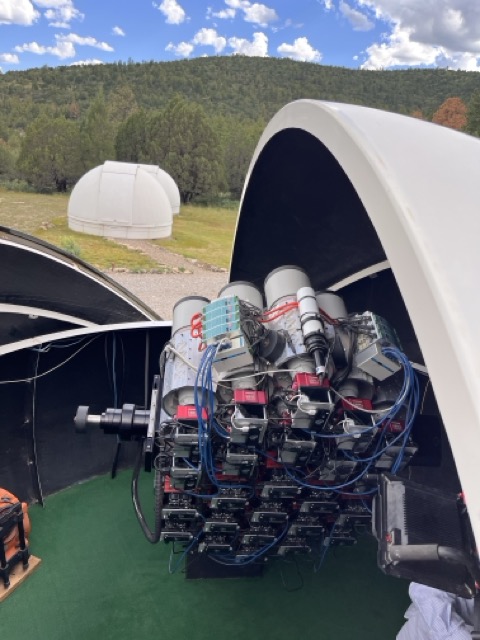
Dragonfly’s architecture offers several properties that are directly advantageous for wide-field optical polarimetry. Its modular design allows individual lens–detector units to be equipped with different polarizer orientations, enabling simultaneous measurement of multiple linear polarization states across the full field of view in a single exposure. This capability is difficult to achieve with conventional single-aperture telescopes. The all-refractive optical design is particularly well-suited to polarimetry, as refractive optics with nano-fabricated anti-reflection coatings suppress scattering and minimize such systematics. In contrast, internal reflections in mirror-based telescopes introduce instrumental polarization that must be carefully characterized and corrected. Furthermore, Dragonfly’s exceptional sensitivity to low surface brightness emission means that the polarized signal from faint diffuse structures (such as Galactic cirrus) can be detected in practical integration times. The use of commercial telephoto lenses also simplifies polarimetric integration, as the drop-in rear filter slot of each lens provides a natural, repeatable mounting point for polarizer and filter assemblies without modification to the optical path. Together, these properties make Dragonfly a natural platform for a wide-field polarimetric facility, motivating the development of DragonflyPol, described in this paper.
Several optical polarimetry facilities and surveys have recently advanced the field, including RoboPol (Blinov et al., 2023), DIPOL-2 (Piirola et al., 2014), and the ongoing PASIPHAE survey (Tassis et al., 2018), which aims to map interstellar magnetic fields at high Galactic latitudes using a 1.3 m telescope with a field of view. DragonflyPol and PASIPHAE complement each other: PASIPHAE targets high stellar density fields, while DragonflyPol’s large field of view (roughly 20 times larger than PASIPHAE) and exceptional surface brightness sensitivity make it uniquely suited to diffuse, low surface brightness structures such as Galactic cirrus and extended molecular cloud envelopes where individual stars are sparse. These diffuse environments are precisely where some of the most pressing open questions lie: how magnetic fields are organized in the low-density interstellar medium, how dust grain alignment varies across different physical conditions, and how large-scale Galactic magnetic structure connects to the small-scale fields threading star-forming regions. No existing wide-field optical polarimetric facility combines Dragonfly’s field of view, surface brightness depth, and simultaneous multi-angle polarization measurement capability.
DragonflyPol implements wide-field optical linear polarimetry on the Dragonfly Telephoto Array by equipping each lens–detector unit with a fixed linear polarizer and bandpass filter assembly. Polarizers are assigned orientations of 0∘, 45∘, 90∘, and 135∘ in repeating groups across the array, enabling simultaneous measurement of all linear Stokes parameters in a single exposure. The groups are assigned for calibration purposes. The instrument achieved first light in September 2025, and commissioning observations are described in this paper. Calibration methodology, polarimetric performance characterization, and standard star results are presented in a companion paper (Tahani et al. in prep). This paper is organized as follows. Section II describes the science goals motivating DragonflyPol. Section III provides an overview of the Dragonfly Telephoto Array architecture. Section IV presents the laboratory characterization program used to select polarizer components and determine their transmission axis orientations. Section V describes the instrument configuration and on-sky commissioning observations. Section VI summarizes our conclusions.
II Science Goals
DragonflyPol’s wide field of view, exceptional surface brightness sensitivity, and simultaneous multi-angle polarization capability enable a broad range of science goals, described below. Several of these goals, that have been difficult to access with existing facilities, are uniquely addressed by DragonflyPol’s combination of field coverage and depth.
Magnetic Field Mapping and Tomography
Starlight polarization by magnetically aligned dust grains traces the plane-of-sky component of interstellar magnetic fields along the line of sight. When combined with stellar distances from Gaia, these measurements enable tomographic reconstruction of the three-dimensional magnetic field geometry of the interstellar medium (e.g., Panopoulou et al., 2019; Doi et al., 2021; Pelgrims et al., 2024). To date, complete 3D magnetic field vectors in 3D have been reconstructed in only two interstellar regions, incorporating both line-of-sight (Tahani et al., 2018) and plane-of-sky magnetic field observations and providing 6D magnetic maps of the Orion A and Perseus molecular clouds (Tahani et al., 2022a, b). These 6D studies demonstrate that magnetic fields preserve the imprint of large-scale Galactic fields and trace cloud formation and evolution, as previously suggested in line-of-sight field studies of Han and Zhang (2007). DragonflyPol’s wide field of view and surface brightness sensitivity make it well suited to extend such analyses to additional regions, particularly diffuse environments and cloud envelopes where stellar densities are lower and existing narrow-field instruments are less effective.
Cloud and Star Formation
Magnetic fields play a significant role in the star-formation process. The orientation of magnetic fields with respect to density structures has important consequences for star formation (Pattle et al., 2023). For example, magnetic fields parallel to an elongated filamentary cloud would resist the radial collapse of the cloud, while perpendicular fields would resist its azimuthal collapse. Understanding the roles that magnetic fields play in this process necessitates mapping both the 3D clouds and their 3D magnetic field vectors (Tahani, 2022). Additionally, understanding how magnetic fields guide the transition from diffuse to dense gas is central to theories of molecular cloud formation and stellar birth. Previous multi-wavelength polarimetric studies of the Orion A and Perseus molecular clouds have revealed how large-scale magnetic field geometry connects to small-scale star-forming structures (Tahani et al., 2022a, b) and how these field morphologies reveal cloud formation history. However, extending these analyses to a broader sample of clouds and environments requires wide-field coverage with high surface brightness sensitivity. These polarimetry studies enabled the identification of superbubbles and bubbles that had shaped the magnetic field geometry and influenced cloud formation. In the case of the Perseus molecular cloud, the reconstructed field lines revealed a structure invisible in total-intensity emission that had shaped the field and influenced the cloud’s formation history; the presence of this structure was subsequently confirmed by independent kinematic observations (Kounkel et al., 2022). DragonflyPol’s large field of view enables simultaneous mapping of magnetic field morphologies across filaments, bubbles, shells, and their surrounding diffuse envelopes (Tahani et al., 2026), connecting the fields threading star-forming regions to the larger Galactic environment and identifying their formation and evolution history.
New Technique for Probing Magnetic Fields
Beyond established polarimetric methods, DragonflyPol’s linear polarimetry capability and wide-field coverage provide a platform for developing and testing new observational techniques for probing magnetic field structure in diffuse environments.
Dust Alignment and Properties
Dust grain alignment by magnetic fields is the physical mechanism underlying starlight polarization. However, the details of alignment efficiency, grain composition, and size distribution across different interstellar environments are not fully understood. One of DragonflyPol’s goals is to compare optical polarization fractions in the -band with far-infrared polarization measurements from other facilities such as Planck or the James Clerk Maxwell Telescope (where available; Tahani et al., 2023). Exploring this ratio enables us to probe how dust alignment efficiency varies between the diffuse and dense regimes traced by optical extinction and thermal emission respectively (Hensley and Draine, 2023). These comparisons provide constraints on grain alignment mechanisms and dust properties across diverse physical conditions, from dense molecular cloud cores to diffuse high-latitude cirrus. In the longer term, multi-band optical polarimetry with DragonflyPol-like configurations will enable direct study of the wavelength dependence of polarization efficiency described by the Serkowski relation (Serkowski et al., 1975). Observing polarization at multiple bands (such as and ) and exploring Serkowski relation enable us to put further constraints on grain size and composition, and will further complement submillimeter polarimetry to build a more complete multi-wavelength picture of dust grain properties (Hensley and Draine, 2023).
Cosmic Microwave Background Foregrounds
Accurate characterization of Galactic dust polarization is essential for separating primordial signals from Galactic foreground contamination in cosmic microwave background (CMB) polarization studies, particularly for detecting B-mode polarization from primordial gravitational waves (e.g., Planck Collaboration et al., 2020). Wide-field optical polarimetry provides tomographic information on the plane-of-sky magnetic field component along the line of sight, which, when combined with stellar distances from Gaia, enables mapping of the three-dimensional distribution of polarizing dust layers contributing to the foreground signal. This three-dimensional view of the foreground dust is a key missing ingredient in current CMB foreground models, which largely treat the polarizing medium as a single layer. DragonflyPol’s combination of wide field of view and surface brightness sensitivity makes it well suited to map these foreground structures in diffuse high-latitude regions where CMB experiments are most sensitive.
Three-Dimensional Structure of High-Latitude Diffuse Clouds
Different studies have explored the 3D spatial structure of some interstellar clouds (Großschedl et al., 2018; Zucker et al., 2021). However, the 3D structure of diffuse, high-latitude clouds remains poorly constrained. Polarimetry of scattered light offers an avenue for recovering 3D cloud geometry, as the polarization state of scattered light encodes information about the spatial distribution of the scattering medium itself (Kishimoto, 1999; Konstantinou et al., 2022). This approach is distinct from magnetic field tomography: rather than tracing field geometry along the line of sight, it uses the polarization signature of scattered light to reconstruct where the scattering material is distributed in three dimensions. DragonflyPol’s wide field of view and exceptional sensitivity to low surface brightness emission make it well suited to applying and further developing these techniques across extended high-latitude structures, where the large angular scales involved make narrow-field instruments inefficient. These observations may also be combined with complementary techniques such as Faraday tomography (Brentjens and de Bruyn, 2005; Van Eck et al., 2017) to build a more complete picture of both the spatial structure and physical conditions of diffuse clouds.
Galactic Magnetic Fields and Large-Scale Structure
On scales larger than individual clouds, the large-scale structure of the Galactic magnetic field and its relationship to the individual clouds remain incompletely mapped, particularly in the optical. Additionally, the magnetic field morphology of the Milky Way’s halo has puzzled different communities for decades (Dickey et al., 2022). Stellar polarimetry with DragonflyPol, with its 5 deg2 field of view, enables efficient mapping of extended Galactic structures that are inaccessible to narrow-field polarimeters, including loops, shells, superbubbles, and high-latitude filaments. These observations will reveal how large-scale Galactic magnetic fields thread through and shape the diffuse ISM, and how field geometry at large scales connects to the smaller-scale fields threading molecular and diffuse clouds. Combined with existing radio and far-infrared datasets, DragonflyPol observations will contribute to building a coherent multi-wavelength picture of Galactic magnetic field structure across a wide range of physical scales.
Optical Polarimetry of Nearby Galaxies
The polarization of light from nearby galaxies encodes information about both the magnetic field structure and dust grain properties within those systems. Optical polarimetry traces starlight polarization by aligned dust grains within the galaxy itself, as well as scattered light from dust in the interstellar medium, probing the plane-of-sky magnetic field geometry and dust distribution across the galactic disk and halo. DragonflyPol’s pixel scale and wide field of view make it well suited to mapping polarization across the extended disks and halos of nearby galaxies, where low surface brightness emission dominates. These observations will complement radio polarimetry and far-infrared dust emission maps of nearby systems, contributing to a multi-wavelength picture of magnetic field structure and dust properties in external galaxies (Wisniewski et al., 2007).
Transients and Serendipitous Discoveries
Polarimetry of transient sources, including supernovae, gamma-ray burst afterglows, and other variable phenomena, can reveal the geometry of the emitting region and the structure of surrounding circumstellar material. While transient science is not a primary focus of DragonflyPol, the instrument’s wide field of view makes serendipitous detection of polarized transients possible during routine survey operations. More broadly, wide-field polarimetric surveys of previously unexplored regions of parameter space have historically led to unexpected discoveries, and DragonflyPol’s unique combination of field coverage and surface brightness sensitivity may reveal polarized structures with no counterpart in existing total-intensity or narrow-field polarimetric surveys.
Axion-Photon Coupling and Fundamental Physics
Axion-like particles are predicted to couple to photons, resulting in oscillation and rotation of the linear polarization angle of linearly-polarized light (Fujita et al., 2019; Oshima et al., 2023). Detection of this effect requires very high-precision polarization angle measurements, as the predicted signal is very subtle. DragonflyPol’s image stacking capability may offer a pathway toward achieving the polarization angle precision required for this study. While current commissioning results establish DragonflyPol as a stable platform for linear polarimetry, achieving the precision necessary for axion-photon coupling searches will require continued refinement of calibration procedures and systematic error characterization, and remains a longer-term goal of the project.
III Dragonfly Overview
Each of the 48 units comprising the Dragonfly Telephoto Array is a completely independent system with its own optical path, detector, and control electronics. As shown in Figure 2, at the heart of each unit is a Canon 400 mm f/2.8 telephoto lens, chosen for its nano-fabricated sub-wavelength anti-reflection coatings that minimize internal light scattering. Focusing is handled by Birger Engineering adapters, which connect the Canon lens to the camera and provide the hardware interface for remote focus commands (Abraham and van Dokkum, 2014; Danieli et al., 2020). The primary detectors are SBIG CCD cameras. Power is distributed to all components through DIN-rail mounted DC power supplies. Each unit is controlled by an Intel Compute Stick microcomputer, which sends focus commands to the lens through a Birger focuser module and exposure commands to the detectors through USB. This modular, self-contained architecture means that each unit can be independently configured, operated, and if necessary reconfigured without affecting the rest of the array. This independent, scalable property is particularly advantageous for polarimetric operations.


Each lens unit accommodates a drop-in filter holder at the rear of the lens, as shown in the top-right panel of Figure 2. In this work we designed a system enabling a single filter holder to serve as the mounting structure for both the bandpass filter and polarizer. The Dragonfly team has previously used Baader SDSS/Sloan and bandpass filters for imaging operations (Danieli et al., 2020). The laboratory characterization of these filters alongside candidate polarizers is described in Section IV.
| Filter | Effective wavelength (nm) | Wavelength range (nm) | Manufacturer |
|---|---|---|---|
| SDSS/Sloan | 636.4 | 571–703 | Baader |
| SDSS/Sloan | 476.4 | 395–559 | Baader |
IV Laboratory Characterization
IV.1 Overview, Goals, and Common Laboratory Setup
During laboratory characterization we primarily focused on (i) selecting a compatible high-performance polarizer and bandpass filter combination for deployment on the array; (ii) measuring contrast ratios and transmission efficiencies of candidate polarizers; (iii) designing a feasible mounting and deployment strategy given overall system constraints; and (iv) determining and marking the transmission axis of each polarizer with repeatable sub-degree precision. To achieve these goals, measurements were conducted in three distinct experimental phases. These phases had different optical components present in the beam path and are described in Sections IV.2, IV.3.1, and IV.4, respectively.
Several components were common to all three phases. The illumination source was a Thorlabs Quartz Tungsten-Halogen lamp (QTH10). The transmission axis orientation of one of the polarizers used in the setup was controlled using a Thorlabs Heavy Duty Rotation Stage (HDR50), driven by a Thorlabs two-channel benchtop stepper motor controller (BSC202). We controlled the motor controller via the Kinesis software interface. A Thorlabs two-axis microscopy joystick console (MJC2) was available for manual polarizer angle adjustment. A Thorlabs iris was placed in the beam path to reduce stray light and improve measurement repeatability. The specific detector, optical path components, and data acquisition method varied by phase and are described in the relevant subsections.
IV.2 Feasibility Tests: Full System Configuration
As an initial feasibility test, measurements were carried out with the full optical system (one optical path unit among the 48 units) in place: a Canon 400 mm f/2.8 telephoto lens, a drop-in filter holder containing a candidate polarizer, a Birger Engineering focuser adapter, and an SBIG camera as the detector. In this setup the bandpass filter was located in front of the illumination source along with another polarizer to produce -band, linearly polarized light. Image acquisition was performed using both MaxIm DL software and FITS image recording through the Raspberry Pi. In this configuration, contrast ratios were measured by comparing median pixel counts in images taken with two polarizers in parallel and orthogonal orientations. The goal in these initial measurements was to examine the feasibility of DragonflyPol, and confining the beam very well was not a priority. These measurements yielded contrast ratios significantly exceeding 100, demonstrating that even with standard commercial polarizers, the system could achieve polarization measurements with better than 1% precision. Additionally, the following tests were performed:
-
•
The lens was swapped between units to confirm that the lens itself did not alter the polarization axis orientation or contrast ratio.
-
•
Careful pressure was applied on the lens to examine the effect of flexure on polarization.
-
•
The illumination spot was moved/translated from the center to the four edges of the lens aperture, as shown in Figure 3, to test for position-dependent polarization effects.
-
•
The polarizer and bandpass filter were inclined by with respect to the normal of the incident beam to simulate the maximum angle of incidence expected in the deployed configuration. By tilting the Canon polarizers from normal incidence we verified that the polarization contrast was not degraded significantly within the imaging cone angle of the Canon lenses at that location of the filter holder.
These results established the feasibility of the DragonflyPol concept and motivated the more systematic characterization described in the following sections.

IV.3 Polarizer Selection
IV.3.1 Lens and Photodiode Configuration
In the second experimental phase, the camera was removed and replaced by a large-area Si photodiode and transimpedance amplifier (Hamamatsu 8746-01) placed at the focal plane of the Canon lens as shown in Figure 4. This configuration allowed more controlled and quantitative measurements of contrast ratio and transmission efficiency for each candidate polarizer, with the photodiode providing a direct, stable readout of transmitted intensity without the additional complexity of image acquisition and reduction.

Four commercially available polarizer types were evaluated: Canon (circular polarizing filter), Edmund (linear), Hoya (linear), and Tiffen (linear). An additional (significantly cheaper) polarizer sourced online was tested briefly but discarded immediately due to poor optical quality. Although the Canon filter is technically a circular polarizing filter, it consists of a linear polarizer followed by a quarter-wave plate, as one polarizing unit. In our measurements it was used as a linear polarizer by orienting it such that the incident light passes through its linear polarizer component first, before its wave plate. Contrast ratios were measured by rotating the second polarizer between parallel and orthogonal orientations relative to the first and recording the photodiode output at each position. Canon and Edmund polarizers were tested in combination with both the Sloan and bandpass filters, as they both showed higher performance compared to Tiffen and Hoya. Transmission efficiency was measured as the ratio of the photodiode signal with a single polarizer in the beam to the signal with no polarizer present.
Representative results are as follows. Edmund–Edmund polarizer pairs achieved contrast ratios typically (noise-subtracted) depending on iris setting and geometry. Canon–Canon and Canon–Edmund combinations achieved contrast ratios of a few (noise-subtracted), typically around . While Tiffen polarizers exhibited high apparent transmission in some configurations, they showed poor contrast ratios (order few) and were not considered further. Hoya polarizers had a higher contrast ratio () compared to Tiffen but lower compared to Edmund and Canon.
Transmission efficiency measurements had a setup shown in the left panel of Figure 5. Canon polarizers achieved approximately 33% transmission in the band with the Baader SLOAN bandpass filter in place. We note that insertion of the bandpass filter reduces overall throughput from 43% in no-filter configuration to 33% when we add the bandpass filter, emphasizing the importance of characterizing the polarizers with bandpass filters in place.


To test for position-dependent polarization effects, the illumination spot was translated to the four quadrants of the lens aperture (Figure 3). Contrast ratio and polarization axis orientation were found to be consistent across the aperture within measurement uncertainties. For the photodection amplifier different transimpedance resistance values were used depending on the measurement goal. For contrast ratio measurements, a high resistance (10 M) was used to maximize sensitivity to the minimum signal in the crossed-polarizer state. For transmission efficiency measurements, a lower resistance (1 M) was used to prevent saturation. Unless otherwise noted, a single resistance value was maintained throughout a given measurement sequence. Canon circular polarizers were selected for deployment on DragonflyPol based on their combination of high contrast ratio, best transmission efficiency across both bandpass filters, consistent performance across units, and straightforward mechanical integration into the drop-in filter holders of the Canon lenses.
Figure 6 shows the measured photodiode response as a function of polarizer rotation angle for a representative Canon polarizer pair, confirming clean Malus’s law behavior across the full rotation range. In this setup, one Canon polarizer was placed in front of the lens and rotated through , and the second was positioned in the drop-in filter holder of the lens.

IV.3.2 Polarizer and Photodiode Configuration (No Lens)
In the third experimental phase, the Canon lens was removed from the setup to obtain cleaner, more controlled quantitative measurements of polarizer performance without potential contributions from the lens optics. In this configuration the beam path consisted of the QTH10 illumination source, iris, polarizer and bandpass filter assemblies, and the Hamamatsu photodiode directly, with no intervening optics. Based on the results of the previous phase, which demonstrated that Canon polarizers with the Sloan bandpass filter provided the better contrast ratio compared to bandpass filter, all subsequent measurements and the final deployed configuration use the bandpass filter.
Contrast ratio measurements in this configuration confirmed and refined the results obtained in Section IV.3.1. Edmund–Edmund polarizer pairs achieved contrast ratios typically (noise-subtracted) in optimized configurations. Canon–Canon and Canon–Edmund combinations achieved slightly higher contrast ratios. Transmission efficiency measurements with the Sloan bandpass filter confirmed Canon polarizers as the best-performing option, achieving approximately 33% single-polarizer transmission. Without the bandpass filter, transmission efficiencies spanned 50–70% depending on polarizer type and geometry.
The illumination source was found to carry a small intrinsic linear polarization at the 1–2% level. This was identified by comparing measurements with and without a polarizer in the beam and is accounted for in calibration. Within measurement precision, no significant instrumental polarization contributions were identified from the tested bandpass filters or mechanical mounts.
These measurements confirmed Canon circular polarizers in combination with the Sloan bandpass filter as the optimal configuration for DragonflyPol deployment, providing the best combination of contrast ratio, transmission efficiency, and consistency across units.
IV.4 Polarization Axis Marking
Following the selection of Canon circular polarizers for deployment, a dedicated scribing station was developed to determine and mark the transmission axis of each polarizer unit with sub-degree repeatability (Figures 7 and 8). Precise knowledge of the transmission axis orientation of each polarizer is essential for accurate Stokes parameter reconstruction.
The scribing station consists of the QTH10 illumination source, a Sloan bandpass filter, a pinhole to define the beam, a polarizing beamsplitter cube serving as the reference axis, a motorized rotation stage, and the Hamamatsu photodiode readout. Several reference polarizer configurations were evaluated for establishing the reference axis, including a nanoparticle polarizer with a known transmission axis; the polarizing beamsplitter cube was found to provide the best combination of alignment precision and repeatability and was adopted as the reference standard for all subsequent scribing measurements.
The transmission axis of each polarizer was determined by rotating it on the motorized stage and recording the photodiode output as a function of angle. The resulting intensity curve was fitted to locate the extrema, from which the transmission axis orientation was determined. A dedicated alignment setup was then used to mark the transmission axis orientation on the filter holder and align the polarizer with it. The bandpass filter and polarizer were subsequently fixed together within the filter holder unit using 3 to 4 dots of UV-cured adhesive (JBweld) applied at the sides, creating an integrated filter+polarizer assembly ready for installation. A machine-shopped protractor was used to mark the filter holder and align the polarizer assembly to the correct position angle during installation into the filter holder. The precision of the polarizer-to-filter-holder alignment is estimated to be better than , and the scribing repeatability is better than .


Table LABEL:tab:scribing and Figure 9 present the scribing characterization results for all 44 Canon circular polarizers (P01–P44), measured on 2025 August 14. For each polarizer, the transmission axis was first located by finding the intensity minimum on the motorized rotation stage and zeroing the stage at that position. Voltages were then recorded at , , , and to verify Malus’s law behavior and confirm the axis determination. The measured ratio is across all units, consistent with ideal Malus’s law behavior to within measurement precision. Raw contrast ratios range from 787 to 1158 with a mean of ; noise-subtracted contrast ratios range from 891 to 1411 with a mean of . All units exceed the minimum contrast ratio of 100:1 established in the feasibility tests (Section IV.2) by more than an order of magnitude. The scribing repeatability is better than as described above.

V Instrument Configuration, Design, and On-Sky Commissioning
V.1 Opto-mechanical Integration and Polarizer Angle Configuration
The DragonflyPol polarimetric capability is implemented by installing a polarizer and bandpass filter assembly into the drop-in filter holder at the rear of each Canon lens. Each assembly consists of a Canon polarizer and a Baader Sloan bandpass filter, fixed together within the filter holder, as described in Section IV.4. This approach requires no modification to the Canon lens or camera, and the assemblies can be installed or removed independently on each unit without affecting the rest of the array. Of the 48 lens–detector units, 44 are equipped with polarizer assemblies. The remaining four units (Dragonfly 111, 124, 205, and 222) carry only an bandpass filter without a polarizer, and serve as unpolarized reference channels for monitoring total intensity and tracking sky transparency variations during observations. The 44 polarized units are organized into 11 Stokes groups, each consisting of four lenses assigned fixed polarization position angles of , , , and respectively. Within each group, simultaneous imaging at all four polarization angles enables reconstruction of the linear Stokes parameters and , and hence the polarization fraction and position angle, from a single set of exposures. Each polarization angle is represented by exactly 11 lenses across the full array, ensuring a balanced contribution to each Stokes parameter. Groups 1–5 are assigned to Mount 1 (Dragonfly 101–124) and Groups 6–10 to Mount 2 (Dragonfly 201–224). Group 11 is distributed across both mounts, with cameras 101 and 116 on Mount 1 and cameras 213 and 216 on Mount 2. This cross-mount assignment was intentional, both to satisfy the constraint that each group must contain exactly one lens at each of the four polarization angles given the physical distribution of available lens positions, and to provide an independent cross-check of the relative calibration between the two mounts. The polarizer angle configuration for both mounts is shown in Figure 10.


V.2 On-Sky Commissioning
Commissioning observations were carried out following integration of the polarizer+filter assemblies on the telescope. The primary goals were to validate (i) camera-to-camera throughput stability across the array, (ii) internal consistency across polarization-angle groups, and (iii) successful measurement of a strong, predictable polarization signal from the twilight sky, specifically the linear polarization arising from Rayleigh scattering, whose degree and position angle can be calculated from the observing geometry and compared directly to the measured values. Twilight flat fields were obtained on three epochs (2025 September 12, 2026 February 8, and 2026 February 9) to evaluate detector and throughput stability across the array. Figure 11 shows the total counts in twilight flat fields grouped by polarization angle for each epoch. The signal levels are broadly stable across units sharing the same polarization orientation, confirming consistent throughput across the polarized lenses. Occasional missing points correspond to dropped frames or temporary malfunctions that were subsequently re-tested. The systematic difference in signal level between polarization-angle groups is the expected polarimetric response of the strongly polarized twilight sky: lenses whose transmission axes are aligned with the dominant sky polarization direction record the highest counts, while those orthogonal to it record the lowest. The uniformity of signal within each group is the diagnostic of instrumental throughput stability.
 |
 |
 |
The twilight sky provides a strong, predictable linear polarization signal arising from Rayleigh scattering of sunlight in the atmosphere, making it well suited for end-to-end validation of the polarimetric system. Table 2 summarizes the measured Stokes parameters, polarization degree, and position angles for all three epochs, alongside the expected position angles computed from the observing geometry. The measured position angles agree with the expected values to within across all three epochs, confirming accurate polarimetric response of the system. The measured polarization degrees range from 0.62 to 0.72, consistent with prior twilight-sky polarization measurements at similar Sun–target separation angles (Cronin et al., 2005). A full treatment of the polarimetric calibration performance is presented in the companion calibration paper (Tahani et al. in prep.).
| Date (UT) | 2025-09-12 | 2026-02-08 | 2026-02-09 |
|---|---|---|---|
| Stokes (=) (standard deviation) | -0.72 (0.03) | -0.46 (0.05) | -0.55 (0.04) |
| Stokes (=) (standard deviation) | +0.03 (0.03) | -0.42 (0.03) | -0.47 (0.04) |
| Polarization degree | 0.72 | 0.62 | 0.72 |
| Polarization position angle | 89.5∘ | 111.5∘ | 110.2∘ |
| Expected position angle | 87.9∘ | 111.2∘ | 110.8∘ |
| -1.6∘ | -0.3∘ | 0.6∘ | |
| Separation angle to the Sun | 84.8∘ | 80.8∘ | 80.9∘ |
| Altitude of the Sun | -6.7∘ | -6.8∘ | -6.7∘ |
| Separation angle to the Moon | 31.1∘ | 54.7∘ | 52.3∘ |
| Altitude of the Moon | 31.1∘ | 54.7∘ | 52.3∘ |
| Moon phase | 64.4∘ | 79.2∘ | 90.1∘ |
VI Discussion and Conclusions
We have presented DragonflyPol, a wide-field optical linear polarimetry capability implemented on the Dragonfly Telephoto Array. DragonflyPol leverages Dragonfly’s modular, multi-lens architecture to obtain simultaneous measurements in four linear polarization orientations (, , , and ) across a field of view. The polarizers are distributed across 44 polarized lens–detector units. The remaining four units serve as unpolarized reference channels.
DragonflyPol commissioning demonstrates that wide-field optical linear polarimetry is achievable with the Dragonfly Telephoto Array using commercial components and a scalable multi-lens architecture. Laboratory characterization confirms that Canon circular polarizers achieve noise-subtracted contrast ratios of (mean = 1228) across all 44 deployed units, with a unit-to-unit standard deviation of 104. These polarizers establish a well-characterized and uniform polarimetric response across the array. The all-refractive optical design minimizes instrumental polarization from internal reflections. These reflections affect mirror-based telescopes and must be carefully modeled and corrected. The scribing procedure yields polarization axis marking repeatability better than , and the protractor-based alignment of polarizers within filter holders achieves a position angle assignment precision of across the array. On-sky commissioning confirms throughput stability across polarization groups and successful recovery of the expected twilight-sky Rayleigh scattering signal.
Since first light in September 2025, DragonflyPol has undertaken an active observing program spanning a diverse range of science targets. Observations to date include wide-field polarimetric mapping of the Galactic cirrus clouds, Perseus molecular cloud, Loop I and Loop III interstellar structures, diffuse high-latitude fields, and several nearby galaxies including M51, M82, M101, and M27. Standard star observations (including both polarized and unpolarized standards) have been interleaved throughout the program to support ongoing calibration, with a particular focus on standard stars during the first few months of operations. Data reduction, calibration methodology, and science results from this program will be presented in future papers in this series.
DragonflyPol represents a demonstration that wide-field optical polarimetry can be implemented using commercial components, with performance suitable for a broad range of Galactic and extragalactic science goals. The success of this program demonstrates a pathway for implementing novel polarimetric capabilities through modular telescope designs using commercial optical components. This modular approach is significantly more cost-effective than purpose-built polarimetric facilities and readily adaptable to other existing or future modular arrays. The instrument’s combination of field coverage, surface brightness sensitivity, and simultaneous multi-angle polarization measurement enables new wide-field optical polarimetric studies of cosmic magnetism, interstellar dust, and the diffuse interstellar medium.
Appendix A Polarizer Scribing Characterization Data
| Polarizer | (mV) | (V) | (mV) | CR (raw) | CR (noise-sub) |
|---|---|---|---|---|---|
| P01 | 9.48 | 9.027 | 1.43 | 952 | 1121 |
| P02 | 8.94 | 9.057 | 1.43 | 1013 | 1206 |
| P03 | 8.30 | 9.063 | 1.43 | 1092 | 1319 |
| P04 | 9.79 | 9.344 | 1.41 | 954 | 1115 |
| P05 | 9.44 | 9.035 | 1.43 | 957 | 1128 |
| P06 | 9.72 | 9.102 | 1.43 | 936 | 1098 |
| P07 | 9.47 | 9.213 | 1.43 | 973 | 1146 |
| P08 | 8.58 | 8.851 | 1.41 | 1032 | 1234 |
| P09 | 9.01 | 8.914 | 1.41 | 989 | 1173 |
| P10 | 9.08 | 9.230 | 1.41 | 1017 | 1203 |
| P11 | 9.33 | 9.243 | 1.41 | 991 | 1167 |
| P12 | 9.83 | 9.118 | 1.41 | 928 | 1083 |
| P13 | 8.44 | 8.922 | 1.39 | 1057 | 1265 |
| P14 | 11.86 | 9.329 | 1.39 | 787 | 891 |
| P15 | 10.60 | 9.221 | 1.40 | 870 | 1002 |
| P16 | 8.01 | 8.874 | 1.40 | 1108 | 1342 |
| P17 | 8.61 | 9.086 | 1.40 | 1055 | 1260 |
| P18 | 8.43 | 8.820 | 1.39 | 1046 | 1253 |
| P19 | 9.36 | 9.121 | 1.39 | 974 | 1144 |
| P20 | 7.74 | 8.960 | 1.39 | 1158 | 1411 |
| P21 | 8.31 | 8.912 | 1.39 | 1072 | 1288 |
| P22 | 7.83 | 8.791 | 1.39 | 1123 | 1365 |
| P23 | 8.98 | 8.968 | 1.39 | 999 | 1181 |
| P24 | 8.11 | 8.922 | 1.39 | 1100 | 1327 |
| P25 | 8.47 | 9.033 | 1.39 | 1066 | 1276 |
| P26 | 8.41 | 8.950 | 1.39 | 1064 | 1275 |
| P27 | 8.54 | 9.007 | 1.39 | 1055 | 1260 |
| P28 | 7.93 | 8.717 | 1.39 | 1099 | 1333 |
| P29 | 7.93 | 8.872 | 1.39 | 1119 | 1356 |
| P30 | 7.92 | 8.758 | 1.39 | 1106 | 1341 |
| P31 | 9.04 | 9.075 | 1.39 | 1004 | 1186 |
| P32 | 8.11 | 8.795 | 1.39 | 1084 | 1309 |
| P33 | 8.00 | 8.688 | 1.39 | 1086 | 1314 |
| P34 | 8.90 | 8.901 | 1.39 | 1000 | 1185 |
| P35 | 8.72 | 8.962 | 1.39 | 1028 | 1222 |
| P36 | 8.57 | 9.008 | 1.39 | 1051 | 1254 |
| P37 | 8.97 | 9.096 | 1.39 | 1014 | 1200 |
| P38 | 7.75 | 8.830 | 1.39 | 1139 | 1388 |
| P39 | 8.55 | 8.799 | 1.39 | 1029 | 1229 |
| P40 | 8.67 | 8.796 | 1.39 | 1015 | 1208 |
| P41 | 8.00 | 8.800 | 1.39 | 1100 | 1331 |
| P42 | 8.69 | 8.719 | 1.39 | 1003 | 1194 |
| P43 | 8.18 | 8.991 | 1.40 | 1099 | 1326 |
| P44 | 9.61 | 8.971 | 1.58 | 934 | 1117 |
| Mean std: | |||||
| – | |||||
References
- Ultra-Low Surface Brightness Imaging with the Dragonfly Telephoto Array. PASP 126, pp. 55–69. External Links: 1401.5473, Document Cited by: §I, §III.
- A high throughput imager at near-ultraviolet wavelengths for a ground-based telescope. In Ground-based and Airborne Instrumentation for Astronomy X, J. J. Bryant, K. Motohara, and Joël. R. D. Vernet (Eds.), Society of Photo-Optical Instrumentation Engineers (SPIE) Conference Series, Vol. 13096, pp. 130963G. External Links: Document Cited by: Table 1.
- The RoboPol sample of optical polarimetric standards. A&A 677, pp. A144. External Links: Document, 2307.06151 Cited by: §I.
- Faraday rotation measure synthesis. A&A 441 (3), pp. 1217–1228. External Links: Document, astro-ph/0507349 Cited by: §II.
- The Dragonfly Nearby Galaxies Survey. V. HST/ACS Observations of 23 Low Surface Brightness Objects in the Fields of NGC 1052, NGC 1084, M96, and NGC 4258. ApJ 868 (2), pp. 96. External Links: Document, 1807.06016 Cited by: §I.
- Polarization patterns of the twilight sky. In Polarization Science and Remote Sensing II, J. A. Shaw and J. S. Tyo (Eds.), Society of Photo-Optical Instrumentation Engineers (SPIE) Conference Series, Vol. 5888, pp. 204–211. External Links: Document Cited by: §V.2.
- The Dragonfly Wide Field Survey. I. Telescope, Survey Design, and Data Characterization. ApJ 894 (2), pp. 119. External Links: Document, 1910.14045 Cited by: §III, §III.
- Structure in the Magnetic Field of the Milky Way Disk and Halo Traced by Faraday Rotation. ApJ 940 (1), pp. 75. External Links: Document, 2209.10819 Cited by: §II.
- Two-component Magnetic Field along the Line of Sight to the Perseus Molecular Cloud: Contribution of the Foreground Taurus Molecular Cloud. ApJ 914 (2), pp. 122. External Links: Document, 2104.11932 Cited by: §II.
- Hunting Axion Dark Matter with Protoplanetary Disk Polarimetry. Phys. Rev. Lett. 122 (19), pp. 191101. External Links: Document, 1811.03525 Cited by: §II.
- 3D shape of Orion A from Gaia DR2. A&A 619, pp. A106. External Links: Document, 1808.05952 Cited by: §II.
- The Galactic distribution of magnetic fields in molecular clouds and HII regions. A&A 464 (2), pp. 609–614. External Links: Document, astro-ph/0611213 Cited by: §II.
- The Astrodust+PAH Model: A Unified Description of the Extinction, Emission, and Polarization from Dust in the Diffuse Interstellar Medium. ApJ 948 (1), pp. 55. External Links: Document, 2208.12365 Cited by: §II.
- The Location of the Nucleus of NGC 1068 and the Three-dimensional Structure of Its Nuclear Region. ApJ 518 (2), pp. 676–692. External Links: Document, astro-ph/9902346 Cited by: §II.
- Polarization power spectra and dust cloud morphology. A&A 663, pp. A175. External Links: Document, 2204.13127 Cited by: §II.
- Dynamical Star-forming History of Per OB2. AJ 164 (2), pp. 57. External Links: Document, 2206.04703 Cited by: §II.
- A Recipe for Unbiased Background Modeling in Deep Wide-field Astronomical Images. ApJ 953 (1), pp. 7. External Links: Document, 2306.07922 Cited by: §I.
- First results of axion dark matter search with DANCE. Phys. Rev. D 108 (7), pp. 072005. External Links: Document, 2303.03594 Cited by: §II.
- Demonstration of Magnetic Field Tomography with Starlight Polarization toward a Diffuse Sightline of the ISM. ApJ 872 (1), pp. 56. External Links: Document, 1809.09804 Cited by: §II.
- Magnetic Fields in Star Formation: from Clouds to Cores. In Protostars and Planets VII, S. Inutsuka, Y. Aikawa, T. Muto, K. Tomida, and M. Tamura (Eds.), Astronomical Society of the Pacific Conference Series, Vol. 534, pp. 193. External Links: Document, 2203.11179 Cited by: §II.
- The first degree-scale starlight-polarization-based tomography map of the magnetized interstellar medium. A&A 684, pp. A162. External Links: Document, 2404.10821 Cited by: §II.
- DIPOL-2: a double image high precision polarimeter. In Ground-based and Airborne Instrumentation for Astronomy V, S. K. Ramsay, I. S. McLean, and H. Takami (Eds.), Society of Photo-Optical Instrumentation Engineers (SPIE) Conference Series, Vol. 9147, pp. 91478I. External Links: Document Cited by: §I.
- Planck 2018 results. VI. Cosmological parameters. A&A 641, pp. A6. External Links: Document, 1807.06209 Cited by: §II.
- Wavelength dependence of interstellar polarization and ratio of total to selective extinction.. ApJ 196, pp. 261–290. External Links: Document Cited by: §II.
- Orion A’s complete 3D magnetic field morphology. A&A 660, pp. L7. External Links: Document, 2203.08763 Cited by: §II, §II.
- 3D magnetic-field morphology of the Perseus molecular cloud. A&A 660, pp. A97. External Links: Document, 2201.04718 Cited by: §II, §II.
- Helical magnetic fields in molecular clouds?. A new method to determine the line-of-sight magnetic field structure in molecular clouds. A&A 614, pp. A100. External Links: Document, 1802.07831 Cited by: §II.
- JCMT BISTRO Observations: Magnetic Field Morphology of Bubbles Associated with NGC 6334. ApJ 944 (2), pp. 139. External Links: Document, 2212.10884 Cited by: §II.
- 3D Magnetic Field Vectors in Space: Bubbles, Clouds, and Filaments. arXiv e-prints, pp. arXiv:2606.27346. External Links: 2606.27346 Cited by: §II.
- Three-dimensional magnetic fields of molecular clouds. Frontiers in Astronomy and Space Sciences 9, pp. 940027. External Links: Document, 2209.12102 Cited by: §II.
- PASIPHAE: A high-Galactic-latitude, high-accuracy optopolarimetric survey. arXiv e-prints, pp. arXiv:1810.05652. External Links: 1810.05652 Cited by: §I.
- A trail of dark-matter-free galaxies from a bullet-dwarf collision. Nature 605 (7910), pp. 435–439. External Links: Document, 2205.08552 Cited by: §I.
- Spatially Resolved Stellar Kinematics of the Ultra-diffuse Galaxy Dragonfly 44. I. Observations, Kinematics, and Cold Dark Matter Halo Fits. ApJ 880 (2), pp. 91. External Links: Document, 1904.04838 Cited by: §I.
- Faraday tomography of the local interstellar medium with LOFAR: Galactic foregrounds towards IC 342. A&A 597, pp. A98. External Links: 1612.00710, Document Cited by: §II.
- The Magnetic Field Structure of the LMC 2 Supershell: NGC 2100. ApJ 664 (1), pp. 296–303. External Links: Document, 0704.3204 Cited by: §II.
- On the Three-dimensional Structure of Local Molecular Clouds. ApJ 919 (1), pp. 35. External Links: Document, 2109.09765 Cited by: §II.