Integrated cloud-based architecture for robot-robot and human-robot collaboration using ROS 2 – MQTT in Mediterranean Greenhouses
Abstract
The imperative to develop more sustainable agriculture demands a transition from isolated automation toward the deployment of multi-robot systems (MRS) in agrifood environments. However, Mediterranean greenhouse settings—characterized by narrow corridors, dense biomass, and structural metallic interference—pose significant challenges for robust and scalable communication between agents. Traditional robotic frameworks, such as ROS 2, frequently encounter node discovery issues and latency spikes due to dynamic obstacles, dense foliage, and other characteristic greenhouse elements, creating a critical bottleneck for real-time coordination. This paper proposes an innovative cloud-based hybrid architecture that establishes a two-way communication bridge between ROS 2, acting as an edge computing platform, and iVeg as a Decision Support System (DSS), using MQTT and the European FIWARE platform. The proposed framework enables seamless interoperability between fleets of multiple robots in environments with communication constraints, facilitating the synchronised exchange of high-level telemetry, point cloud data and farmer identification for collaboration, amongst other critical data. The architecture was validated in a high-fidelity simulation environment and subsequently tested in a real-world greenhouse scenario, demonstrating its ability to maintain persistent connectivity and data integrity under adverse network conditions. The results indicate that the integration of MQTT effectively eliminates information silos, providing a scalable and decentralised solution for managing complex robotic missions, which are executed locally via Edge Computing. This work sets a new methodological precedent for the concept of ‘Greenhouse Models as a Service’ (GMaaS), bridging the gap between low-level robotic control and high-level, cloud-based IoT decision-making.
keywords:
Agricultural Robotics , Mobile robotics , Multi-Robot Systems , Human-robot interaction , Collaborative Robotics , Internet of Things , CEA[UAL-Inf] organization=Department of Informatics, CIESOL, ceiA3, Universidad de Almería, addressline=Ctra. Sacramento s/n, city=Almería, postcode=04120, country=Spain
[UAL-Eng] organization=Department of Engineering, CIESOL, ceiA3, Universidad de Almería, addressline=Ctra. Sacramento s/n, city=Almería, postcode=04120, country=Spain
1 Introduction
Over the last few decades, greenhouse agriculture has consolidated as a pivotal strategy for enhancing food productivity while optimizing water and energy resource management. These advancements are driven, in part, by the progressive integration of automated systems and advanced control mechanisms in critical processes such as temperature, humidity, and ventilation management (Van Straten and Van Henten, 2010). Within the field of automation, mobile robots designed for transportation, inspection, and operator assistance have emerged as essential agents in the transition toward digitized and connected agriculture (Hernández et al., 2025). Although greenhouses are structured environments, they pose significant challenges for autonomous mobility: narrow corridors that maximize cultivation area at the expense of manoeuvrability; terrains with non-linear behaviors—including slippage, heterogeneous compaction, or the presence of crop residues, or dynamic obstacles in general, and fluctuating environmental conditions (Cañadas-Aránega et al., 2024a, 2026a). These factors hinder navigation and necessitate robust control strategies capable of ensuring precise and safe motion even under high degrees of uncertainty.
Beyond the individual capabilities of a single platform, the true optimization of these agricultural environments lies in the deployment of Multi-Robot Systems. Shifting from single-agent operations to autonomous robot fleets allows for large-scale tasks—such as distributed harvesting or efficient monitoring—to be addressed cooperatively, thereby increasing system resilience and reducing execution times through operational parallelism (Das and Jain, 2025; Moreno et al., 2024). However, coordinating multiple units within the confined spaces of Mediterranean greenhouses introduces a critical layer of complexity: the requirement for robust and constant data exchange. In these scenarios, communication management becomes a technological bottleneck; the high density of vegetation and structural interference demand network architectures capable of guaranteeing real-time agent synchronization (Bezerra et al., 2026).
In this context, the integration of the Internet of Things (IoT) emerges as a key paradigm for enabling interoperable and trustworthy robotic fleets, managing the communication complexity of distributed systems while fostering transparency through open data ecosystems Khanh et al. (2022). Conceptually, IoT establishes a ubiquitous network of interconnected objects, including devices, sensors, actuators, and robotic agents, which converge into a digital ecosystem for bidirectional data exchange. This synergy not only bridges the physical greenhouse environment with virtual control layers but also enables integrated architectures capable of processing massive data streams across heterogeneous domains Elijah et al. (2018). While IoT deployment has transformed sectors such as smart cities Zanella et al. (2014), campus management Chang and Lai (2018), and home automation Handarini and Wulandari (2020), its application in autonomous vehicles and agricultural robotics Muñoz et al. (2020a) represents currently the technological frontier for achieving field-deployable, trustworthy distributed autonomy. Standardizing robot orchestration via IoT protocols stands as a key strategy to deliver interpretable, contextual data from the field to human operators, transforming raw telemetry into active decision support.
This new approach requires the development of transversal protocols, interoperability, and close cooperation between services and systems. Currently, a significant portion of research focuses on cooperative robotic systems that enhance operational efficiency by combining mechanical precision with advanced perception and teamwork capabilities in shared environments Lytridis et al. (2021). However, this introduces additional design complexity: the need to capture, in real-time, the localization and status of each agent in both simulated and real-world environments. The optimal strategy for managing this information flow relies on wireless data exchange via the Internet, facilitating the integration of IoT architectures for real-time communication. This challenge is particularly critical within the technical atmosphere of a greenhouse Muñoz et al. (2020b), where environmental complications must be emulated in high-fidelity simulators to validate communication through shared data clouds prior to physical implementation. In this sense, intelligent robotic agriculture transcends mere automation by integrating Big Data services, Cloud Computing, and Farm Management Information Systems (FMIs) powered by Artificial Intelligence Muñoz et al. (2020a). Nevertheless, integrating these services in agricultural environments remains a complex task requiring high-performance connectivity to ensure precision in robot navigation. To overcome these barriers, the use of cloud platforms providing open data management systems that easily integrate heterogeneous devices enables the evolution toward "Greenhouse Models as a Service" (GMaaS) models, optimizing system scalability and flexibility.
To address the critical connectivity and data management challenges previously outlined, this paper contributes to the digitalization of the agricultural sector by presenting a cloud-based architecture specifically engineered for robotic fleets operating in dynamic environments. The fundamental novelty of this proposal lies in providing a robust communication framework for high-complexity scenarios, such as Mediterranean greenhouses. In these settings, dense biomass and extremely narrow aisle configurations cause severe degradation of conventional wireless signals and constant sensory occlusions, which render current multi-robot communication solutions practically unfeasible. The proposed approach overcomes these limitations by transforming visual detections of operators and other robots into lightweight geometric metadata. This information is synchronized via a bidirectional ROS 2-MQTT bridge with the iVeg platform Macenski et al. (2022); Muñoz et al. (2020a). Fundamentally, this architecture enables a cooperative safety mechanism where robots maintain shared spatial and collaborative awareness. By broadcasting the real-time coordinates of detected farmers, peer agents can execute pre-emptive deceleration reducing their velocity by 50% even when the obstacle is situated outside their immediate field of view. By replacing bandwidth-intensive data streams with optimized JSON messages, the architecture ensures the persistence of fleet-wide situational awareness, even in areas with minimal connectivity Švec et al. (2022). As detailed in the literature review, no previous work natively integrates ROS 2 with an MQTT cloud infrastructure to guarantee distributed safety and autonomy in highly occluded, collaborative protected cultivation environments.
Based on the technical literature review, the gaps this work intends to bridge have been identified. Consequently, the primary contributions of this article are summarized as follows:
-
1.
Multi-Robot Architecture for Greenhouses: This work presents the development of a high-fidelity simulation environment and real-world trials that enable the integration of cooperative robotic fleets. This architecture ensures that interoperability among heterogeneous agents translates into a shared world model, allowing robots to perceive human presence through inter-agent data exchange.
-
2.
Human-Robot Interaction: The proposed architecture guarantees that interoperability among heterogeneous agents results in a shared world model including farmers, enabling robots to proactively perceive human presence through the exchange of localised agent data.
-
3.
Hybrid Network Architecture for Critical Connectivity: An innovative cloud-based solution utilizing MQTT and FIWARE is proposed to optimize real-time data handling. This demonstrates that lightweight messaging is the optimal solution for maintaining persistent synchronization in greenhouse infrastructures where network stability is frequently compromised by biomass.
-
4.
Bidirectional Safety Bridge between FIWARE - MQTT - ROS 2: This work establishes a robust bidirectional communication bridge between ROS 2 and MQTT in accordance with the FIWARE standard. For the first time, this integration is utilized to implement closed-loop safety commands from the cloud, enabling automatic speed modulation based on collective intelligence.
The rest of the article is organised as follows. Section 2 presents a review of the state of the art in current multi-robot systems in agriculture and the IoT technology used. The materials and methods used are described in Section 3. The detailed description of the architecture is explained in Section 4. Section 5 discusses the description of the experiments carried out. Finally, Section 6 is devoted to some conclusions.
2 Related Work
To provide a comprehensive context for the proposed architecture, this section reviews the state of the art in collaborative and cooperative agricultural robotics, IoT-robotic integration, and interoperable data models. By analyzing these domains, the technical gaps, specifically regarding communication persistence and cross-platform synchronisation, are highlighted to show what this work seeks to overcome.
2.1 Multi-Robot cooperation in Agriculture
Cooperative robotics has emerged as a disruptive paradigm for addressing the labor-intensive nature of modern farming, particularly within protected cultivation environments. Farella et al. (2024) underscored that while the potential for efficiency is high, the deployment of Multi-Robot Systems in confined spaces faces significant constraints regarding spatial navigation and real-time synchronization. In this context, heterogeneous fleets comprising robots with varying kinematic constraints have gained significant research attention. For instance, Fawakherji et al. (2019) demonstrated that collaborative sensing enriches data management for crop classification. Building on this foundation, Roldán et al. (2016) proposed a decentralized coordination framework for multi-robot harvesting, emphasizing the need for an interoperable communication layer to bridge the gap between low-level control via ROS 2 and high-level decision-making (Cloud-IoT). Furthermore, the work of Lytridis et al. (2021) suggests that the future of greenhouse robotics lies in "Swarm-to-Cloud" architectures, where multiple agents utilize lightweight protocols such as MQTT to maintain a shared world model despite signal attenuation caused by metallic greenhouse structures. Despite these advances, a clear research gap remains regarding the provision of a unified, real-time communication bridge that ensures the scalability of these cooperative tasks within Mediterranean-style infrastructures.
This challenge is further exacerbated by the hostile nature of the greenhouse environment for wireless communications. Research on signal propagation in dense crops, such as the work by Ferentinos et al. (2017), demonstrates that high foliage density and humidity levels act as physical barriers, causing severe multi-path fading and energy absorption that degrade link quality. Beyond ground-based platforms, Boursianis et al. (2022) explored the integration of Unmanned Aerial Systems (UAS) for mission-critical monitoring, employing heuristic techniques such as particle swarm optimization to manage complex trajectories in greenhouses. This physical instability directly impacts the transport layer in the Open Systems Interconnection (OSI) model (Antonelli, 2013); studies on IoT protocols in precision agriculture by Hernández et al. (2025) point out that although protocols like MQTT are lightweight, their reliance on TCP leads to critical delays and constant retransmissions in environments with high packet loss due to plant obstacles, thereby compromising real-time data delivery. Recent studies by Miele et al. (2025) highlight that coordination within greenhouses is severely hampered by the absence of reliable communication middleware capable of handling the high data throughput required by vision-based learning approaches. Therefore, the transition from individual automation to collective intelligence remains a technological bottleneck.
2.2 Deep Learning and Machine Learning Vision Model in Agriculture
In the domain of autonomous agricultural vehicles, deep learning-based perception has transitioned from generic monitoring to mission-critical multi-agent safety. Advanced object detection models, particularly the YOLO (You Only Look Once) family, have become the standard for enhancing detection accuracy in unstructured environments (Wang et al., 2024). However, in Mediterranean greenhouses, the extreme density of biomass and narrow aisle configurations pose a dual challenge: they create constant sensory occlusions for local vision systems and simultaneously degrade wireless signals, hindering the exchange of raw visual data. Recent studies emphasize that while YOLOv8 and YOLOv10 provide superior identification of personnel and heterogeneous robot morphologies (Cañadas-Aránega et al., 2024a), their utility in multi-robot coordination is often bottlenecked by the inability of standard networks to transmit high-bandwidth information in such occluded settings.
To address these challenges, recent research has shifted toward perception-driven communication architectures. Instead of transmitting heavy video streams, optimized frameworks focus on the extraction of lightweight geometric metadata specifically 2D bounding box coordinates and class probabilities to maintain real-time fleet synchronization (Luo et al., 2016). While heavy architectures like ResNet or VGG16 suffer from high computational latency (Chen and Ran, 2019), the integration of attention mechanisms, such as the Convolutional Block Attention Module (CBAM), has significantly improved bounding box regression accuracy, allowing for precise distance estimation between cooperative agents and farmers even under non-linear lighting (He et al., 2019). The state-of-the-art now suggests that bridging these ROS 2-based local detections with MQTT-based cloud infrastructures is the only viable path for distributed autonomy in dense crops (Arslan et al., 2014). This approach enables a shared world-model where local perception enriches global awareness without saturating the constrained bandwidth of protected cultivation environments.
2.3 IoT Integration in Multi-Robot Systems in Greenhouses
The convergence of robotics and IoT has fostered the concept of the Internet of Robotic Things (IoRT), where local processing capabilities are augmented by cloud-based resources. Numerous studies have explored the use of IoT to enhance the control and monitoring of autonomous agents, initially employing short-range technologies such as Bluetooth (Khoje et al., 2016), Wi-Fi (Madkar et al., 2016), ZigBee (Wan et al., 2009), and Wireless Sensor Networks (WSN) (Mishi et al., 2017). However, these solutions often exhibit limitations in expansive agricultural settings due to restricted coverage ranges and high sensitivity to physical obstructions. To overcome these barriers, recent literature has shifted toward multilayered systems that integrate distributed Edge-Computing nodes with scalable IoT Cloud platforms. These advanced architectures leverage decentralized middleware and low-latency communication protocols to orchestrate autonomous robots, enabling high-throughput data orchestration in complex domains such as precision agriculture (Ramesh et al., 2020), perimeter surveillance (Telkar and Gadgay, 2020), and emergency rescue operations (Vanitha et al., 2016).
Despite these developments, the current state of the art reveals that interoperability between heterogeneous robots and sensors remains an open challenge, particularly in scenarios demanding real-time data management. Recent research by Ojha et al. (2021) suggests that conventional ROS 2 protocols (based on DDS) frequently encounter node discovery issues in Wide Area Networks (WAN), which has motivated the adoption of lightweight messaging protocols such as MQTT. However, the implementation of an efficient bidirectional bridge between the ROS 2 ecosystem and cloud-distributed MQTT brokers specifically tailored for environments with high humidity and structural occlusion, such as greenhouses remains a critical area of exploration.
2.4 Data Models and Standards in IoT
Data interoperability is a key concern in IoT. Works such as Savaglio et al. (2018) and Fortino et al. (2020) emphasize the importance of standardized data models to facilitate the integration of heterogeneous platforms. However, existing proposals often lack validation in real-world agricultural environments or fail to address real-time data integration between robots and sensors. Models like OMA NGSI have gained attention for their ability to ensure semantic and syntactic interoperability, but their specific application in collaborative robotics remains limited (Kovacs et al., 2016).
Studies such as that of Muñoz et al. (2020b) highlight the importance of developing IoT solutions for integrating data generated by sensors in greenhouses, demonstrating the practical application of interoperability frameworks in controlled environments. By the effective processing of sensor data and the use of robotics, these solutions address farmers’ needs by combining the precision and power of robotic platforms with the flexibility of cloud-based communication architectures, even in complex scenarios such as greenhouses (Corista et al., 2018). However, existing proposals often lack validation in agricultural environments or do not address real-time data integration between robots and sensors.
3 Materials and methods
In this study, a robust multi-robot communication architecture has been developed to integrate robotic agents operating under ROS 2 Humble Hawksbill through the MQTT protocol and the FIWARE ecosystem (Macenski et al., 2022; Quincozes et al., 2019; FIWARE, 2026). This architecture is specifically designed to facilitate bidirectional data exchange within Mediterranean greenhouses—environments characterized by high signal attenuation and latency spikes caused by dense biomass and dynamic obstacles. The high-level system topology is illustrated in Figure 1. The communication pipeline is structured as follows: robotic nodes publish telemetry and environmental data via MQTT to the FIWARE Orion Context Broker, which serves as the backbone for the iVeg platform. This integration establishes a scalable cloud-based application layer where high-level decision-making algorithms aggregate multi-source data to orchestrate coordinated robotic actions. The following subsections detail the materials and methodologies employed in the design and validation of this architecture
3.1 Materials
This section describes the materials used, beginning with a description of the greenhouse and the real robots, and 3D models used for the simulations.

3.1.1 AgroConnect greenhouse facilities
The experimental trials were conducted at the AgroConnect facilities (funded by the Ministry of Science, Innovation, and Universities and the European Regional Development Fund - FEDER, grant 2019) located in Almería, Spain () (Figura 2).

The site is situated at an elevation of 3 m above sea level, featuring a consistent 1% northern slope across the terrain. The testing grounds consist of a 1,850 m² Mediterranean-style greenhouse (locally known as ”raspa y amagado“), characterised by a robust steel structural frame and a high-density polyethene cladding. From a robotics perspective, the facility is designed around a 2 m wide central corridor that acts as the primary navigation artery, connecting to eleven lateral aisles on each side (Figure 3). From the central corridor, 22 corridors branch off to the north and south; those to the north are 12.5 m long, whilst those to the south are 22.5 m long, all of them 2 m wide without taking plants into account.

The facility hosts a commercial tomato crop (Lycopersicon esculentum) cultivated in coconut fiber (coir) bags arranged in strict north-to-south rows. Advanced climate control infrastructure including zenithal and lateral natural ventilation, an integrated HVAC network, CO2 enrichment, and high-pressure humidification systems maintains optimal agronomic conditions.
3.1.2 Simulator for AgroConnect greenhouse
To validate the safety and interoperability of the multi-robot coordination algorithms before physical deployment, the proposed framework was first evaluated within a high-fidelity simulation environment. It utilised a detailed 3D digital twin of the AgroConnect greenhouse, originally developed in SolidWorks and validated for autonomous navigation in (Cañadas-Aranega et al., 2024) (Figure 4).
This model meticulously replicates the architectural complexity of the real facility, including primary structural columns and diagonal reinforcement elements, faithfully represented according to their real-world spatial configuration. Furthermore, a high-resolution 3D botanical model of the pear-tomato plant (Lycopersicon esculentum) was integrated (see Figure 5).
Both the vegetation and the structural pillars were positioned within the virtual world to strictly match their actual coordinates in the experimental site. For the purpose of this study, a m virtual testbed was constructed, featuring five corridors separated by 4 m. Each lane is flanked by the aforementioned hydroponic tomato crop, effectively defining the navigation corridors for the multi-robot fleet. This environment accurately replicates the characteristic geometry and occlusion patterns of Mediterranean greenhouses, providing a proper base for validation of autonomous navigation and coordination algorithms previously established in the literature (Cañadas-Aránega et al., 2026a).


3.1.3 Fleet of Intelligent Robotic Agents
The experimental multi-robot fleet comprises two distinct mobile platforms engineered to act as transparent, internet-connected agents. These units, the mobile robots AgriCobIoT I (Moreno Úbeda et al., 2022) and AgriCobIoT II (Cañadas-Aránega et al., 2024a) are integrated into a cloud-based architecture through localized fog and edge computing layers. This design enables the robots not only to execute local manoeuvres autonomously but also to expose their internal edge-perception states to human supervisors in real time.
-
1.
AgriCobIoT I (AGI)
Based on the commercial Husky platform, AGI utilizes a differential drive system capable of executing zero-radius turns, an essential kinematic requirement for navigating the abrupt transitions between the central corridor and the narrow cultivation aisles. To support human workers, the platform features a custom-built ergonomic superstructure tailored for automated crate transportation. This architecture includes four central support pillars and a removable, rail-guided mechanism engineered for standard agricultural boxes. Safety and proximity sensing are managed by base-level ultrasonic arrays, while a specialized rear mast houses a height-adjustable perception payload dedicated to human detection and tracking during collaborative tasks (Moreno Úbeda et al., 2022; López-Gázquez et al., 2023). The physical system is depicted in Figure 6b. Its virtual counterpart leverages a computationally optimized .dae mesh balanced with simplified collision primitives to ensure stable rigid-body physics simulation (Figure 6a).

(a) 
(b) Figure 6: Real 3D models and AGII used For the purpose of this study, the platform is equipped with the following core hardware layer:
-
(a)
HITTSON Industrial Control Unit: A high-performance onboard computer that serves as the agent’s edge-computing core. It features an integrated Wi-Fi 6 (802.11ax) module, enabling low-latency, bidirectional telemetry exchange with the local greenhouse router.
-
(b)
Intel RealSense D435 RGB-D Camera: An active stereo depth sensor utilized as the primary vision engine. Crucially, this sensor does not stream heavy, privacy-invasive raw video feeds to the cloud. Instead, it feeds high-resolution spatial data directly into the local edge deep-learning model, extracting precise 3D bounding boxes ( coordinates) and model confidence levels to generate lightweight, human-interpretable geometric metadata.
-
(c)
Velodyne VLP16: A 16-channel Time-of-Flight (ToF) laser scanner featuring a horizontal field of view. Characterized by its compact form factor and high sampling rate (up to points/s), this sensor is pivotal for Simultaneous Localization and Mapping (SLAM) and real-time obstacle and ground detection (Cañadas-Aránega et al., 2026b). Within this study, it provides the high-fidelity spatial data required to validate navigation safety and maneuverability within the constrained aisles of a greenhouse environment.
-
(d)
Taobotics 9-axis IMU: An Inertial Measurement Unit fused with wheel odometry. By outputting real-time linear accelerations and angular velocities, it guarantees robust pose estimation across the irregular, sloped, and low-traction soils of Mediterranean greenhouses, ensuring that the spatial explanations sent to the user interface remain physically accurate.
These sensors are also simulated in the virtual environment.
-
(a)
-
2.
AgriCobIoT II (AGII)
Designed at the University of Almería, AGII provides a complementary kinematic profile to the fleet (Cañadas-Aránega et al., 2024a). It utilizes an Ackermann steering geometry with a nominal 2 m turning radius. While structurally constrained by this steering mechanism, AGII compensates with a heavy-duty payload capacity of 150 kg, making it optimal for large-scale crop hauling. Mirroring AGI’s layout, its chassis optimizes sensor placement and crate allocation to streamline harvesting workflows. A secondary rear mast houses an identical perception payload to maintain fleet-wide data symmetry during autonomous tracking operations. The physical realization and corresponding 3D mesh of AGII are shown in Figure 7.
The same sensors used in the physical model have been also incorporated into the 3D model as well.


3.1.4 MultiVehicle Simulator (MVSim)
For the pre-operational assessment, a simulation is created in the MultiVehicle Simulator (MVSim) (Blanco-Claraco et al., 2023), an environment that supports real-time simulation of multiple vehicles or robots in simple and complex settings, and it runs in ROS. MVSim uses realistic physics-based friction models to accurately simulate the interaction between the tires and the ground. The simulator supports using the most common modern mobile robotics and autonomous vehicle research sensors, such as RGB-D cameras or 2D and 3D LiDAR scanners. All depth-related sensors can accurately measure distances to user-supplied 3D models to define elements of a custom environment using acceleration based on the Graphics Processing Unit (GPU). When working with ground vehicles, the simulator is very efficient, as a simplified 2D physics engine is used for body-to-body collisions and to resolve wheel-ground interaction forces separately, used in previous works such as (Cañadas-Aránega et al., 2026a). By importing the exact .dae structures of AGI and AGII, MVSim acts as an effective auditing tool for the explainable safety framework. As illustrated in Figure 8, the simulation world was populated with lifelike 3D human models (representing greenhouse personnel), standard tomato crates, and manual harvesting trolleys.

3.2 Methods
This section describes the methods and algorithms used in the development of multi-robot system, which details the ROS 2 middleware used, the farmer recognition methodology, the communication protocols and the multisensor network that has been built.
3.2.1 Robot Operating Systems 2 (ROS 2)
The core of the robotic software architecture is built upon ROS 2 Humble Hawksbill, which serves as the distributed middleware for high-level task orchestration and hardware abstraction. Unlike its predecessor, ROS 2 leverages the Data Distribution Service (DDS) standard to provide the Quality of Service (QoS) policies essential for maintaining reliable communication in the unpredictable conditions of a greenhouse (Macenski et al., 2022). In this multi-robot framework, ROS 2 facilitates inter-agent interoperability by utilizing standardized message interfaces that allow heterogeneous platforms to share a unified world model. To ensure scalability and prevent data interference, each robot operates within a dedicated namespace, allowing the MQTT bridge to aggregate local perception data into a global fleet management layer without cross-talk. Furthermore, the system employs the tf2 transform library to synchronize the spatial coordinate frames of all agents, transforming local YOLOx detections into a shared global map. This integration of decentralized communication and real-time spatial synchronization transforms individual autonomous units into a cohesive, perception-aware fleet capable of the complex cooperative navigation and collaborative human-robot interaction required in dense agricultural environments (Macenski et al., 2020).
3.2.2 Farmers and Robots Recognition with YOLOx
To facilitate transparent agent identification within the occluded greenhouse environment, a vision-based object detection system utilizing the YOLOx frameworkIIIYOLOx-ROS repository: https://github.com/Ar-Ray-code/YOLOX-ROS/tree/humble (an adaptation of YOLOv10 for ROS 2) was implemented and optimized for the Humble distribution. Unlike multi-stage detection methods, YOLOx processes images in a single neural network pass with AI. This edge-computing approach ensures the ultra-low latency required for proactive safety maneuvers and dynamic obstacle avoidance. From an explainability standpoint, the core strength of YOLO lies in its holistic image processing; it evaluates contextual information to drastically reduce false-positive detections, laying a reliable foundation for human-robot trust. The architectural structure of the deployed YOLO network is illustrated in Figure 9 (Yayla et al., 2025).

This versatility, combined with its refined architecture and a user-friendly API, makes YOLO a powerful choice for field-deployable computer vision tasks (Xu et al., 2024). YOLO reframes object detection as a single regression problem, directly predicting spatial bounding boxes and class probabilities. The core of its mathematical formulation is the loss function, which is a weighted sum of three main components: localization loss, confidence loss, and classification loss (Zhang et al., 2025). This unified approach allows the model to predict bounding boxes and class probabilities simultaneously in real-time. The total loss function is defined in Eq. (1).
| Loss | (1) | |||
The parameters and components in this equation are interpreted as follows:
-
1.
: The number of grid cells in the input image (e.g., a grid means ).
-
2.
: The number of bounding boxes that each grid cell is configured to predict.
-
3.
: An indicator function that is 1 if the -th bounding box in the -th grid cell is responsible for detecting an object, and 0 otherwise.
-
4.
: An indicator function that is 1 if the -th bounding box in the -th grid cell does not contain any object.
-
5.
: The predicted bounding box coordinates (originating at the lower left vertex) and dimensions.
-
6.
: The ground truth (actual) bounding box coordinates (originating at the lower left vertex) and dimensions.
-
7.
: The predicted confidence score for a bounding box.
-
8.
: The ground truth confidence score. This is 1 if the box contains an object and 0 otherwise.
-
9.
: The predicted class probability for class .
-
10.
: The ground truth class probability.
-
11.
(Lambda Coordinate): This crucial hyperparameter weighs the importance of the localization loss. It is typically set to a high value (e.g., 5) to ensure the model prioritizes learning to accurately locate objects.
-
12.
(Lambda No-Object): This hyperparameter reduces the influence of the no-objectness loss. Since most grid cells do not contain any objects, the no-object confidence loss would easily dominate the overall loss. A low value (e.g., 0.5) is used to balance this effect.
To transform 2D pixel-level BB classifications into spatially grounded, human-interpretable metrics, the proposed framework extends the edge-comp
-uted YOLOx detections into 3D metric space. This spatial alignment is essential for a field-deployable DSS, as farmers and robots must appear at the correct coordinates on the robots’ edge maps and on the iVeg map for the farmer; while raw 2D bounding boxes hold little semantic meaning for a grower monitoring fleet operations, 3D coordinates relative to the greenhouse topology provide actionable, transparent insights. To achieve this without streaming high-bandwidth data, the local robotic nodes utilize an optimized 3D projection pipeline inspired by the YOLACT_ros_3dIIIIIIYOLACT_3D repository: https://github.com/IntelligentRoboticsLabs/yolact_ros_3d/tree/master framework, which maps localized instance representations directly against the registered depth point cloud captured by the Intel RealSense D435 camera. The local detection masks are encoded as optimized bitsets. For a given pixel at coordinates , where represents the column and represents the row, the membership function within the localized region of interest is defined as:
| (2) |
where the bit position is computed as:
| (3) |
| (4) |
| (5) |
and is the mask width, is the byte index, and is the bit index within that byte. Protruding greenhouse foliage often fringes the visual boundaries of targets, causing erratic depth readings that degrade human-robot trust. To filter this noise, an adaptive morphological erosion is applied before 3D projection. The kernel area relies on a class-specific erosion factor :
| (6) |
A cross-shaped structuring element () of size iteratively erodes the original mask via morphological opening until peripheral artifacts detach:
| (7) |
where is the total number of iterations. For each eroded pixel (), its 3D coordinate is retrieved. Given the YOLOx 2D center , width , and height , where and represent the local row and column indices within the mask, the top-left corner of the bounding box is computed to map the 2D pixel to the 3D point cloud index:
| (8) |
| (9) |
where is the total point cloud width. To prevent erratic depth jumps caused by layered crop rows, a point is only accepted if it satisfies a depth discontinuity constraint:
| (10) |
where filters background clipping. This physically validates the semantic confidence of the YOLOx model. The 3D bounding box is formed using the filtered set of valid points :
| (11) |
where and define the spatial boundaries along the X-axis, calculated as and . Here, denotes the X-coordinate of the -th 3D point belonging to the filtered vertex set . The boundary pairs for the Y and Z axes ( and ) are derived analogously from their respective spatial components ( and ). To optimize edge processing, only detections meeting the confidence threshold () are computed. The final spatial centroid and dimensions are:
| (12) |
Finally, coordinates are transformed from the robot’s egocentric view to a unified global map using ROS 2 TF2, allowing the DSS to present a coherent world model:
| (13) |
This information is updated for every frame in the /yolact_coordinate topic in ROS 2. Consequently, the topic contains the information shown in Table 1
| Parameter | Description |
| object_name | Object name. |
| probability | Probability of certainty. |
| xmin | X coordinate in meters of the left upper corner of the bounding box. |
| xmax | X coordinate in meters of the right lower corner of the bounding box. |
| ymin | Y coordinate in meters of the left upper corner of the bounding box. |
| ymax | Y coordinate in meters of the right lower corner of the bounding box. |
| zmin | Z coordinate in meters of the nearest pixel of the bounding box. |
| zmax | Z coordinate in meters of the furthest pixel of the bounding box. |
In conclusion, the YOLO framework algorithm follows these steps:
-
1.
The Intel RealSense D435 camera captures a frame structured as a pixel matrix.
-
2.
YOLOx processes this matrix and locates an object (for example, the ”farmer“ class). The network generates a 2D bounding box defined by its centre, width and height in pixels.
-
3.
From there, YOLACT generates a binary mask (a bitmap) cropped exactly to the size of that bounding box. and are the iterative indices used by the loop in your code to traverse, pixel by pixel, that local mask.
-
4.
If the pixel at position has a bit set to 1 (i.e., belongsToMask(x, y) = 1), this means that this particular pixel is part of the farmer’s or robot’s body and not part of the background.
3.2.3 MQTT
MQTT (Message Queuing Telemetry Transport) is a lightweight communication protocol designed for IoT and M2M applications. Its publication and subscription-based architecture allows information to be exchanged efficiently through a centralized model managed by a broker, which organizes messages into topics accessible to publishers and subscribers. One of its most outstanding features is its optimization for resource-constrained devices and low-capacity networks, thanks to a fixed header size of only 2 bytes. MQTT includes three Quality of Service (QoS) levels, which guarantee the delivery of messages with varying degrees of reliability. In this design, the AGI and AGII robots communicate by sending information from the relevant ROS 2 topics, as shown in Figure 10.
3.2.4 FIWARE
FIWARE is a framework developed as part of a European initiative to drive the adoption of IoT platforms and foster sustainability in smart applications (FIWARE, 2026). This modular system is based on a set of Generic Enablers (GEs) that simplify the development of IoT solutions through standardized functionalities such as contextual data management, open APIs, and information processing.
A key element of FIWARE is the Orion Context Broker (OCB), which acts as the core of any solution based on this framework, managing contextual data in real time using the OMA NGSI model (Kovacs et al., 2016). IoT Agents play a crucial role in translating information from IoT devices into the NGSI standard format, supporting protocols such as MQTT (Quincozes et al., 2019), CoAP (Shelby et al., 2014), and OPC UA (Derhamy et al., 2017). This interoperability makes FIWARE especially relevant for applications that require efficient integration and scalability in heterogeneous environments, such as smart greenhouses.
3.2.5 iVeg DSS Interface
iVeg serves as the user-facing interface within this architecture. Built on top of FIWARE, it transforms the standardized NGSI data streams into an interactive, web-based situational awareness platform. Instead of merely displaying raw robot coordinates, iVeg contextualises the decision-making process for the greenhouse manager. It provides real-time, synchronized representations of the environment, visualizing the exact locations of the fleet alongside the 3D bounding boxes of detected human operators or obstacles, displaying the classes detected on the robots’ local maps and on the website set up for farmers. By exposing the fleet’s intent, dynamic costmaps, and decision certainty thresholds, iVeg bridges the gap between robotic automation and human oversight, fostering trust in the system’s reliability. Its modular architecture facilitates the incorporation of new devices, services, and analytical tools, making iVeg suitable for research and experimentation in smart agriculture and robotic applications.
3.2.6 Sensor Fusion and Decision Algorithm
The proposed decision-making algorithm integrates heterogeneous sensor data for real-time environmental interpretation and cloud-based synchronisation via the Internet of Things (IoT). Each robotic unit is equipped with a HITTSON onboard computer acting as the central processing hub, interfaced with an RGB-D camera, LiDAR, IMU, and motor encoders to continuously evaluate the operational workspace. This unit identifies human operators and robotic peers (AGI/AGII) to facilitate data dissemination across the local network infrastructure, all within the edge computing environment. The perception pipeline employs the YOLOx framework—specifically fine-tuned for this application—for real-time inference on the incoming video stream, extracting class identifiers and confidence scores for transmission via the MQTT protocol to a FIWARE-based cloud platform. Furthermore, a spatial localisation algorithm processes the YOLOx bounding boxes to determine the 3D positions of the detected objects relative to the camera’s optical centre; this spatial metadata is also forwarded to the iVeg DDS. Within this architecture, iVeg filters these detections, ensuring that only entities that meet a predefined probability threshold are classified as confirmed agents, thereby providing the entire fleet with the precise locations of nearby farmers and other classes. To enable distributed situational awareness, each robot transmits odometry data derived from LiDAR and wheel encoders to determine its precise global pose. This information is shared across the fleet to update local costmaps with the positions of dynamic obstacles in real time, allowing the system to track both human operators and robotic peers simultaneously.
The DDS enforces safety through a hierarchical rule-based logic that prioritises human safety. Specifically, when YOLOx detects a farmer, the system broadcasts the 3D coordinates to a dedicated node on each robot that continuously monitors the MQTT data stream. If incoming data confirms human presence within the greenhouse, the system generates a 2-meter-radius "warning zone" around each operator. Within this zone, robots are mandated to reduce their operational speed by half. In the absence of human presence, the system manages multi-robot interactions by evaluating the task status of detected peers. When a robot identifies another unit, its location is shared via MQTT/FIWARE, and a similar warning radius is established to mitigate collision risk. These velocity adjustments are implemented directly within the motion control node, which applies a 0.5 scalar multiplier to the cmd_vel topic, effectively reducing the voltage supplied to the actuators. Ultimately, this multi-sensor fusion approach ensures that safety constraints override standard navigation commands, thereby enhancing the reliability of autonomous operations in the dynamic, unstructured conditions of protected cultivation.

4 Robot-robot and human-robot collaboration architecture
The AgroConnect greenhouse is equipped with an advanced IoT-enabled architecture designed to facilitate efficient data management and interoperability. The architecture integrates multiple layers—perception, processing, and application—ensuring seamless collaboration between heterogeneous components such as sensors, actuators, and cloud services. Although this architecture was presented in a basic version in a previous paper (Muñoz et al., 2020b), the current implementation has evolved to incorporate advanced robotic capabilities, enabling autonomous operations and improved data exchange. This section describes the proposed architecture, beginning with an overview of the existing layers within the greenhouse and the communication methodology between robots.
4.1 IoT-based architecture in the AgroConnect greenhouse
-
1.
Perception Layer: The perception layer represents the foundation of the architecture, consisting of various physical components deployed in the greenhouse. This includes:
-
(a)
Sensors and IoT devices: Used for monitoring key environmental variables such as temperature, humidity, and CO2 levels.
-
(b)
Robots (AGI and AGII): Integrated for cooperative tasks such as navigation, data collection, etc.
-
(c)
Other equipment: Components such as thermal panels, fertigation systems, and reverse osmosis devices contribute to the efficient management of resources.
-
(a)
-
2.
Data Storage and Processing Layer: This layer is central to managing and processing data generated by the perception layer:
-
(a)
FIWARE Enablers: Components such as the Orion Context Broker, IoT Agents, and Cygnus handle real-time contextual data and ensure interoperability using the OMA NGSI standard.
-
(b)
MQTT Broker: Facilitates lightweight communication between sensors, robots, and cloud services.
-
(c)
ETL Processes: Support the extraction, transformation, and loading of data into dedicated databases (e.g., MongoDB, PostgreSQL) for further analysis
-
(a)
-
3.
Application Layer: The application layer provides interfaces and services for decision-making and visualization:
-
(a)
Dashboards: Enable real-time monitoring of greenhouse conditions and robot operations.
-
(b)
REST APIs: Offer external access to processed data for integration with external systems or services.
-
(c)
Digital Twins and Advanced Analytics: Allow simulation and predictive modeling to optimize greenhouse operations.
-
(a)
This layered architecture (see Figure 11) not only ensures efficient data processing and interoperability but also supports real-world operations through seamless integration of sensors, robots, and cloud services. The following section illustrates specific examples of how this architecture enables practical workflows in the AgroConnect greenhouse.

4.2 Cooperative and Collaborative Robot Logic
This section describes the workflow that enables an example of cooperation between the AGI and AGII robots within the greenhouse on the iVeg platform (see Figure 14) when one robot detects another via its sensors or by sending a command from the control panel. Furthermore, when the robots detect a farmer, they also send them the necessary information so that both robots can take the appropriate actions, adapting their behaviour to the presence of humans. This communication is managed through the publication and processing of data via the MQTT broker, conversion to NGSI in the IoT Agent, and the generation of commands in the Orion Context Broker. The interaction and communication with the dashboard are described below.
4.2.1 Robot-Robot Bidirectional Bridge
To ensure decentralized safety, the fleet maintains a continuous, low-latency communication mesh by ROS 2 Humble and a custom-developed Bridge Node. The core of this integration is a custom-developed Bridge Node, which functions as a bidirectional gateway between the robotic middleware and the cloud infrastructure. Internally, ROS 2 utilizes a Publish-Subscribe pattern where vision nodes (YOLO) and the MVSim simulator (for virtual environments) or the physical robot (for real-world trials) provide asynchronous data streams.
The Bridge Node serializes high-level metadata at 30 Hz, packing the robot’s states, linear/angular velocities, and active 3D YOLO BoundingBoxes. Upon reception, the system executes a JSON serialization process: rather than forwarding bandwidth-heavy raw images, it filters classification metadata—such as Class ID and probability—and encapsulates it into a lightweight MQTT payload (see Algorithm 1 and Figure 12). Simultaneously, the node processes ground-truth odometry and transformed LiDAR scan vectors to synthesize a shared, cross-fleet costmap. This architecture ensures that every autonomous unit maintains persistent, identical knowledge of its peers’ physical boundaries without overwhelming the greenhouse’s wireless network bandwidth (see Figure 13).

A specialized background node, mqtt_feedback, continuously queries the cloud broker to retrieve the real-time spatial trajectories of neighboring agents. Concurrently, the deterministic decision-making logic (detailed in Section 4.3) tracks these incoming classification labels and confidence metrics (see Algorithm 2).
Whenever an agent registers a person or a peer, a fleet-wide geospatial alert is broadcasted. Upon receiving this message, the neighboring robot computes an immediate proximity analysis relative to its own kinematic path. If the trajectory intersects with the 2-meter safety zone of a farmer or the safety buffer of a peer, the recipient robot initiates a preemptive velocity reduction (see Algorithm 3). This mechanism acts as an extended safety horizon: it grants the robot spatial awareness of human presence well beyond its immediate line-of-sight, overrules active navigation commands to force a predictable deceleration, and exposes this entire safety state to the iVeg interface for complete human validation. Finally, it updates the map in RViz and displays the class detected by the other robot to define the safety radius. At the same time, iVeg updates its map on the dashboard so that the farmer can see where the other farmers are.

4.3 Communication workflow between robots by the iVeg Dashboard
This section details the comprehensive semantic workflow designed to operationalize real-time, explainable monitoring and multi-agent cooperation between the AGI and AGII units, as well as their context-aware interaction with human operators via the iVeg platform (see Figure 14). By leveraging an IoT-standardized layered architecture anchored on MQTT and OMA NGSI, the framework transforms raw, uninterpretable edge-computed sensor data into high-level, human-centric actionable insights for transparent fleet management.

-
1.
Perception Layer - Data Generation and Publication (Onboard): Each robot gathers critical navigation and environmental data through its sensor suite, including LiDAR, RGB-D cameras and odometry. The ROS 2 Bridge MQTT component acts as an intermediary, converting internal ROS 2 messages into lightweight MQTT topics. This information is published to the MQTT Broker under the following topics, following the IoT Agent format /{apikey}/{device}/attrs:
-
(a)
/{apikey}/AGI_odom and /{apikey}/AGII_odom: Robot position (), orientation (), and velocities ().
-
(b)
/{apikey}/AGI_lidar2D and /{apikey}/AGII_lidar2D: LiDAR point clouds for localization.
-
(c)
/{apikey}/AGI_yolox_bounding_boxes and /{apikey}/AGII_
yolox_bounding_boxes: YOLOx detection metadata (class, confidence, bounding box, 3D position).
-
(a)
-
2.
Data Storage and Processing Layer - Standardization and Cloud Integration: To ensure that the fleet’s cognitive state is interoperable and open to external auditing, the telemetry is routed through a cloud-based standardization pipeline:
-
(a)
Reception and Translation via IoT Agent: The IoT Agent subscribes to the relevant MQTT topics and functions as a gateway that translates incoming data into the OMA NGSI format. This ensures data interoperability and seamless integration into the FIWARE ecosystem. For instance, data from /{apikey}/AGII_odom
/attrs is transformed into an NGSI entity with base_pose_groun
d_truth attributes, while /{apikey}/AGII_lidar2D/attrs maps to lidar_points and /{apikey}/AGII_yolox _bounding_boxes
/attrs maps to bounding_boxes. -
(b)
Integration with Orion Context Broker: The IoT Agent forwards the translated data to the Orion Context Broker, where it is stored as FIWARE entities available for real-time queries. In Listing 1 an example of a unified robot state entity and its standardized attributes is shown.
-
(c)
MongoDB Database: The Orion Context Broker shares a MongoDB database with the IoT Agent and the REST API for historical data persistence, enabling longitudinal analysis and trend identification.
Listing 1: Structure of the NGSI-v2 Entity for the Robot’s Status in Orion Context Broker {"id": "AGX","type": "Robot","base_pose_ground_truth": {"type": "object","value": {"x": 14.134062767,"y": 11.46727562,"yaw": -0.386157338,"linear_velocity": 0.999,"angular_velocity": 0.34}},"bounding_boxes": {"type": "object","value": {"class_id": "farmer","probability": 0.945,"position": {"xmin": 0.4506256580352783"ymin": -0.3164764642715454"xmax": 0.7936256527900696"ymax": 0.11368180811405182"zmin": -0.25958430767059326"zmax": 0.10506562888622284}}},"lidar_points": {"type": "array","value": [5.3208699226379395,5.330774307250977,5.321296691894531,...]},"metadata": {"TimeInstant": {"type": "DateTime","value": "2026-04-26T10:21:14.660Z"}}} -
(a)
-
3.
Application Layer - iVeg Dashboard Visualization:
The iVeg platform acts as the bridge between machine logic and human supervision, translating complex digital twin data streams into global situational awareness. This layer operationalizes the transparency goals through four core capabilities:
-
(a)
Reception and Translation via IoT Agent: The primary contribution to the collaborative workflow is the deterministic propagation of risk awareness. When the iVeg DSS processes an entity classification matching a ”person“ or ”robot“ with confidence score , it automatically triggers a fleet-wide feedback loop. The system formats and publishes this alert metadata (data.position, data.class, data.conf, timestamp) to the corresponding feedback topic (/AGI/mqtt_feedback or /AGII/mqtt_feedback), mandating an immediate, proactive 50% kinematic speed override on any unit operating within that zone.
Updating the dashboard’s semantic map: Instead of displaying abstract lists of coordinates, the interface generates an interactive semantic map in real time. Following confirmation by the DSS, the user interface automatically projects a spatial marker that dynamically traces a 2-metre safety radius around the human operator, both on the fleet’s shared-cost maps and on the manager’s control panel.
-
(b)
Human-in-the-Loop Kinematic Override: To preserve human agency over autonomous behaviors, the UI features explicit manual control mechanisms. Operators can instantly issue an emergency STOP command. This instruction is routed via NGSI-v2 down to the IoT Agent, which publishes a high-priority payload to the robot’s command topic (/{apikey}/AGI/cmd or /{apikey}/AGII/
cmd), forcing an immediate mechanical shutdown that completely overrides any ongoing autonomous navigation task. -
(c)
MongoDB Database: The Orion Context Broker shares a MongoDB database with the IoT Agent and the REST API for historical data persistence, enabling longitudinal analysis and trend identification.
-
(a)
5 Results and Discussion
This section describes the simulations and experiments designed to validate the proposed approach, as well as the results obtained.
5.1 Validation in the Simulated Greenhouse
For this study, a preliminary simulation was designed and executed within a 3D greenhouse model previously established in (Cañadas-Aránega et al., 2026a), utilizing real-world data collected from the (Cañadas-Aránega et al., 2024a) dataset. The simulation environment was developed using the MVSim simulator (Blanco-Claraco et al., 2023), which is particularly suited for these scenarios due to its high-fidelity physical modeling. MVSim provides realistic friction models, a critical factor when addressing the complexities of greenhouse environments characterized by uneven soil and loose earth surfaces.
A total of five simulations were conducted across four distinct scenarios: i) farmer detection from various perspectives; ii) AGX robot identification from multiple angles; iii) simultaneous appearance of a farmer and AGX unit within the same frame; and iv) farmer and AGX unit detection under partial occlusions within the field of view. Out of all trials, 18 were successfully completed, yielding an overall success rate of 92%. The details of the simulation and the results obtained are set out below.
5.1.1 Simulation setup
This section describes the simulation setup, which will be used as a model for real-world tests.
-
1.
3D model of the greenhouse
For this work, a 20 × 20 m virtual greenhouse model was constructed, consisting of five corridors, each bordered on both sides by tomato plants and separated by 4 m, thereby defining the robot’s navigation lanes. This model has previously been used in the study (Cañadas-Aránega et al., 2026c), supporting its application to the real-world model. The 3D model closely replicates a real pear-tomato crop grown in a hydroponic system and the characteristic geometry of a Mediterranean greenhouse. This realistic representation provides a reliable testbed for validating navigation algorithms previously applied in related research (Cañadas-Aránega et al., 2024b, c). The model is shown in Figure 8 and, to adapt it to the real-world environment, four realistic models of farmers, stacked crates of tomatoes and two transport trolleys have been implemented; these models correspond to those found in the actual AgroConnect greenhouse.
-
1.
AGI 3D model
The AGI robotic asset simulates an autonomous scouting platform. All onboard sensory data streams are structurally referenced to its egocentric coordinate frame. The payload comprises a 3D LiDAR (Velodyne VLP16) dedicated to planar mapping and a forward-facing RGB-D camera (Intel RealSense D435) rigid-mounted at coordinates (0.4, 0.0, 0.6) m to optimize the optical field of view. The camera’s factory-calibrated intrinsic parameter matrices are integrated directly into the local ROS 2 projection nodes, enabling the instantaneous translation of 2D bounding boxes into metric 3D coordinates relative to the optical center. The RGB-D sensor provides synchronised colour and depth information, enabling the direct estimation of the distance to detected objects from the bounding box in the YOLOACT algoritm.
-
1.
AGII 3D model
The AGII asset represents a heavy-duty crop transport platform operating under loaded structural conditions. It is equipped with a co-aligned 3D LiDAR (Ouster OS0) and a stereo vision system (Point Grey Bumblebee2) mounted at a baseline height of (0.35, 0.0, 0.6) m. The stereo system extracts spatial depth via localized disparity matching between the synchronized left and right image frames, providing a secondary, independent pipeline for 2D-to-3D projection verification. The intrinsic parameters used are detailed in (Cañadas-Aránega et al., 2024a). The fixed baseline of the stereo system enables reliable depth estimation, allowing the 3D position of detected objects to be computed relative to the robot.
5.1.2 Training YOLO for robot recognition
Regarding the robot detection process, the YOLOx model was trained for 25 epochs with an input resolution of pixels using a Pascal VOC format. The dataset comprised 2,200 images (1,100 of each AGI and AGII robot, including 3D and real-world models ) covering various perspectives and occlusion scenarios within the greenhouse environment. Such training was not required for the farmer class, as a pre-trained human recognition model was included. The dataset was partitioned into pascal/train and pascal/valid directories. Training was executed via the command model.train(data=’data.yaml’, epochs=25, imgsz=224, batch_size=8, plots=True) and subsequently exported to the OpenVINO format using model.export(format="openvino"). The training phase was conducted on a local workstation equipped with an NVIDIA RTX 4060 GPU (8 GB), an Intel Core i7-13400 CPU, 32 GB of Kingston DDR4 RAM (3200 MHz), and a 1 TB Kingston NV2 NVMe SSD. This hardware configuration provided sufficient computational throughput and memory bandwidth for real-time image processing, Convolutional Neural Network (CNN) training, and validation tasks, ensuring stable and efficient model convergence.
The system is capable of inter-agent detection with an average confidence probability of 85%. Figures 15 and 16 illustrate the identification process of the AGI and AGII robots during simulation trials, as well as the identification of the farmer. Furthermore, the YOLOx performance metrics are summarized in Table 2 using the eval.py file provided by the algorithm. The results demonstrate that the model operates with high precision, reliably performing recognition tasks for both robotic agents and human operators.
The network achieves a global mean precision of 89.90% and an average precision (AP@0.5) of 0.91. Crucially, the system exhibits an exceptionally low False Negative (FN) profile for the ”Farmer“ class (, ). Minimizing false negatives is paramount for human-centric robotics; it ensures that the system rarely misses a human operator under challenging canopy conditions, thereby preventing unexpected or un-auditable movements that could severely degrade grower trust. Consequently, certain real-world challenges—such as variable lighting, motion blur, and partial occlusions—which may occasionally lead to classifications, were not fully encountered. To address these limitations, the following section details the deployment of the robots in a physical greenhouse environment to evaluate their robustness under real-world operational constraints.
5.1.3 Real-time updating of the semantic map via in simulation
This section examines the multi-robot communication architecture based on a DSS at iVeg in simulation, detailing how the map is updated in real time locally on the robots and how the map on the iVeg dashboard is updated to facilitate interaction with the farmer.
-
1.
Communication and update of the local robot semantic map
To evaluate the proposed framework’s capability to mitigate spatial blind spots and extend the perceptual horizon, a collaborative non-line-of-sight (NLOS) validation scenario was executed. A critical challenge in dense greenhouse cultivation is the severe occlusion of human operators or mobile assets caused by heavy foliage canopies and structural crop rows. To replicate this real-world operational constraint, the AGII logistic robot was initialized in a navigation corridor completely devoid of a direct line of sight to either the AGI scouting platform or the human operator. Under traditional, isolated control architectures, AGII would remain entirely unaware of peripheral hazards until an immediate, near-collision event occurred. Within the proposed transparency framework, the cloud-based Decision Support System (DSS) functions as a decentralized cognitive bridge. As the AGI platform navigates along the central greenhouse corridor, its edge-computing pipeline continuously scans the environment. The moment the onboard YOLOx inference engine detects the human operator beneath dense canopy occlusions (see Fig. 17), the spatial grounding node estimates the target’s absolute metric coordinates within the global frame. This high-level semantic metadata is immediately encapsulated and streamed to the iVeg DSS via the MQTT transparency channel.
The Orion Context Broker processes this incoming state transition and instantly routes the updated context entities down to the background synchronization nodes of the sensor-deprived asset (AGII). Upon receiving this telemetry, AGII’s local navigation stack executes a dynamic costmap injection. As visualized in the RViz interface (Fig. LABEL:fig:rviz_local), the physical footprints and active safety envelopes of both the peer AGI node and the human grower are dynamically mapped onto AGII’s local costmap in real time, successfully overcoming the complete absence of physical, egocentric sensory contact. The evaluation metrics for this simulation are presented in Table 2.

(a) 
(b) Figure 15: Identification YOLO from AGI 
Figure 16: Farmer and AGI identification from AGII Table 2: Performance metrics of the YOLOX model for object detection in the greenhouse environment (simulation). Class True positive (TP) False positive (FP) False negative (FN) Precision (%) Recall (%) AP@0.5 Farmer (Human) 42 3 1 93.33 97.67 0.94 Robot AGI 18 2 2 88.89 92.52 0.92 Robot AGII 28 4 3 87.50 87.56 0.88 \rowcolor[HTML]EFEFEF Average (mean) - - - 89.90 92.58 0.91 Total (global) 88 7 6 90.05 92.70 - 
(a) 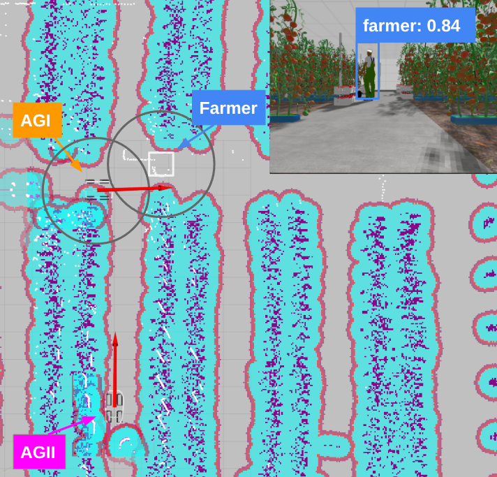
(b) Figure 17: Simulation update AGII local map As a direct consequence of this cross-agent synchronization, when the AGII robot advances toward the newly projected warning zone, its local safety node registers the intersection with the human’s 2-meter bounding safety envelope. The system triggers an immediate kinematic override, successfully throttling its linear velocity down by 50% to an operational safety ceiling. This predictive deceleration validates the system’s capacity to maintain comprehensive operational safety and human-centric transparency well beyond the immediate, egocentric line of sight of individual robotic assets.
-
2.
iVeg Dashboard Multi-Robot Telemetry Contextualization
Once the vision nodes were validated, the communication pipeline was integrated with the iVeg application layer (Figure 18). Rather than acting as a standard engineering telemetry logger, the iVeg interface functions as an Explainable, explicitly decoding the fleet’s internal world-model for the human supervisor through five synchronized visualization widgets:
-
(a)
Dynamic Semantic 2D Map: Projects a continuous top-down cartographic representation of the greenhouse lanes. It displays the synchronized poses of the fleet alongside real-time coordinate projections of the AGI (rendered in red) and AGII (rendered in blue) LiDAR point clouds. This global spatial grounding removes the opaqueness of decentralized multi-agent locations.
-
(b)
Kinematic State Feedback: Extracts and renders the precise global Cartesian spatial coordinates () and orientation (Yaw) variables directly from the OCB’s digital twin entity.
-
(c)
Proactive Speed Gauges: Individual visual speedometers map the real-time linear velocities of the fleet in m/s. This widget explicitly displays the immediate physical consequences of the safety overrides when a robot approaches a dynamic boundary.
-
(d)
Action and Inference Log: A dedicated, chronological telemetry log that couples each YOLOx detection event with its exact timestamp, source asset, target class, and confidence probability. Crucially, it prints the explicit rationale behind any velocity modulation (e.g., displaying due to human proximity versus upon clearance), granting the user complete, deterministic logical traceability.
-
(e)
Deterministic Emergency Controls: Standardized interface overrides that allow the supervisor to publish high-priority mechanical commands via OMA NGSI down to the /{apikey}/{device}/cmd MQTT channel, providing an immutable human-in-the-loop safety layer.
To rigorously evaluate the temporal determinism of the communication channel, the experimental data were used to evaluate both central tendency and tail-end dispersion metrics. The mean values quantify the expected steady-state performance, whereas the 95th percentile (P95) metrics isolate transient worst-case latency spikes caused by CPU scheduling contentions or network jitter. The resulting empirical temporal data of the efficacy of the communication framework Table 3, where it presents the end-to-end latency decomposition across the full ROS 2–MQTT–FIWARE pipeline, measured over two experimental sessions totalling over 100,000 messages. The analysis distinguishes between two latency components: the MQTT transport latency (ROS 2 to the MQTT broker) and the FIWARE processing latency (from the MQTT broker to the Orion Context Broker), providing a detailed view of where delays are introduced in the system.

Figure 18: iVeg dashboard for multi-robot monitoring during simulation. The interface shows the 2D greenhouse map with AGI (red) and AGII (blue) LiDAR point clouds and robot trajectories, real-time pose (, , Yaw), individual speed gauges, manual STOP command buttons, and the YOLO Detection Log with confidence scores and speed change events. Table 3: End-to-end latency decomposition for the ROS 2–MQTT–FIWARE pipeline in simulation. MQTT transport latency (): ROS 2 MQTT broker (co-located LAN deployment). FIWARE processing latency (): MQTT broker IoT Agent Orion Context Broker MongoDB. Total = + . Data Type mean P95 mean P95 Total mean Total P95 Odometry 3.8 ms 11.2 ms 98.4 ms 182.3 ms 102.2 ms 193.5 ms YOLOx 4.1 ms 12.5 ms 101.2 ms 188.7 ms 105.3 ms 201.2 ms LiDAR 2D 4.3 ms 13.1 ms 96.1 ms 155.4 ms 100.4 ms 168.5 ms The communication pipeline achieved a 100% message delivery rate with zero packet dropouts across all simulation cycles. Under Local Area Network (LAN) conditions, the transport overhead () remained negligible, maintaining a mean of approximately 4 ms. This demonstrates that the serialization logic executing on the ROS 2 edge node introduces no critical computational bottlenecks. The dominant component is the cloud-based processing chain ( mean 99 ms), which encompasses OMA NGSI schema parsing, context entity creation within the Orion Context Broker (OCB), and database commit execution.
From a communication architecture perspective, the global end-to-end P95 latency consistently remains below 202 ms across all semantic data types, including the dense spatial arrays of the YOLOx bounding boxes. This sub-quarter-second latency guarantees real-time visual parity between the physical kinematics of the mobile robots and the graphical representations rendered on the iVeg interface.
-
(a)
5.2 In-Field Validation in the Experimental Greenhouse
To validate the operational robustness and adaptability of the transparent cloud-robotics framework under unconstrained real-world conditions, both robotic assets were deployed within the physical AgroConnect greenhouse facility. The experimental campaign was designed around a rigorous validation matrix comprising four distinct operational scenarios executed across multiple field runs: i) farmer grower tracking from variable, unconstrained viewpoints; ii) multi-angle inter-agent identification of the robotic peers; iii) simultaneous co-presence of a human operator and a robotic unit within the same camera frame; and iv) multi-agent tracking under severe partial occlusions induced by overlapping tomato crop rows.
The camera intrinsic parameter configurations utilized during the simulation phase were transferred directly to the physical edge nodes. Across the entire experimental campaign, a high operational completion rate of 82% was achieved, demonstrating the stability of the end-to-end cloud-edge communication pipeline under real agricultural network constraints.
5.2.1 Real Edge-YOLO validation
The deep-learning weights optimized during the simulation phase were compiled and deployed onto the onboard processing units of the physical fleets. Within the unstructured physical environment, the perception engine achieved inter-agent and human tracking with a global mean confidence probability of 72%. Figures 19 and 20 illustrate the real-time inference outputs and bounding box groundings executed by the AGI and AGII assets during the live harvest trials.
The YOLOx model utilized for the detection of farmers and robotic agents was further evaluated using the custom in-field dataset, achieving a global recognition precision of 79.03% during real-world navigation trials. This performance represents an 11.02% macro degradation compared to the 90.05% global precision obtained during idealized simulation baselines. Despite this expected decrease—driven by real-world agricultural challenges such as dynamic solar glare, plastic-diffused lighting, and multi-layered leaf occlusions—these results validate the robustness of the edge-computing perception modules. Even when operating with low-resolution physical sensors, the framework reliably supports safe, collaborative navigation between humans and robots.
From the perspective of the proposed architecture, a cross-sensor comparison reveals that the active RGB-D configuration of the Intel RealSense camera exhibited significantly greater resilience to sudden lighting transients and high-frequency motion blur than the passive Bumblebee2 stereo vision system, which struggled with texture homogeneity against the dense crop backdrop. Nevertheless, the human supervisor can monitor, in real time, both the operational progress of the fleet and the ongoing state transitions occurring within the greenhouse environment.
5.2.2 Real-world experimental validation updating of the semantic map
This section examines the multi-robot communication architecture based on a DSS at iVeg in the real greenhouse.
-
1.
Experimental upgrading of the local robot semantic map
To validate the physical efficacy of the decentralized context-propagation pipeline, an in-field stress test was executed within the physical AgroConnect greenhouse. In this unconstrained environment, physical variables such as shifting foliage canopy density and unexpected structural obstacles introduce real-world processing and network propagation bottlenecks, the specific latency profiles of which are rigorously dissected in the subsequent section. In this experiment, the AGII logistic asset was deployed in the central corridor, deliberately oriented in the opposite direction of the active cultivation rows where human operators were performing harvesting tasks. Simultaneously, the AGI scouting node was positioned directly facing a grower to perform localized edge inference. AGI’s perception engine resolved the spatial coordinates of the operator, packaging this semantic metadata alongside its own egocentric odometry profile for immediate cloud publication via the MQTT bridge.

(a) 
(b) Figure 19: YOLO farmer and AGII recognition from real AGI 
Figure 20: Farmer and AGI identification from AGII The results of this live synchronization are detailed in Figure 21 and Table 4. Figure LABEL:fig:mvsim_result captures the absolute ground-truth physical disposition of the assets alongside the onboard YOLOx detection overlay from the AGI node. Concurrently, Figure LABEL:fig:rviz_local2 displays the live state of AGII’s local costmap monitored via RViz.
Table 4: Performance metrics of the YOLOX model for object detection in the greenhouse environment (real world). Class True positive (TP) False positive (FP) False negative (FN) Precision (%) Recall (%) AP@0.5 Farmer (Human) 36 6 3 85.71 92.31 0.94 Robot AGI 34 8 5 80.95 87.18 0.88 Robot AGII 28 12 8 70.00 77.78 0.88 \rowcolor[HTML]EFEFEF Average (mean) - - - 78.89 85.76 0.90 Total (global) 98 26 16 79.03 85.96 - 
(a) 
(b) Figure 21: Real update AGII local map As demonstrated by the empirical results, despite AGII’s physical optical sensors pointing in the completely opposite direction of the active workspace, the underlying FIWARE-MQTT cloud orchestration layer successfully bypassed its localized line-of-sight limitations. The blind asset seamlessly resolved and rendered the real-time spatial footprints of both its peer unit (AGI) and the human operator within its local navigation costmap. This decentralized awareness eliminates the hazardous opacity of isolated robotic agents, ensuring that even sensor-deprived assets maintain complete, auditable situational awareness of human workers across the shared agricultural environment.
-
1.
iVeg Dashboard multi-robot communication in real greenhouse
To guarantee that the iVeg dashboard functions as a dependable, real-time reflection of the fleet’s cognitive state, the underlying ROS 2–MQTT–FIWARE communication infrastructure was subjected to a rigorous latency profiling analysis under live greenhouse operating conditions. Maintaining a bounded, low-latency telemetry channel stands as a fundamental requirement. The empirical temporal data logged during active in-field navigation are systematically decomposed in Table 5. This breakdown isolates the transport latency (: edge serialization to the MQTT broker) from the cloud orchestration latency (: broker parsing, OMA NGSI translation via the IoT Agent, Orion Context Broker synchronization, and historical MongoDB persistence).
Table 5: End-to-end latency decomposition for the ROS 2–MQTT–FIWARE pipeline. MQTT transport latency (): ROS 2 MQTT broker, measured from real robot captures ( per type), clock-offset corrected. FIWARE processing latency (): MQTT broker IoT Agent Orion Context Broker MongoDB, measured via TimeInstant polling (, network one-way delay subtracted). Total mean = mean + mean. Data Type mean P95 mean P95 Total mean Total P95 Odometry 16.9 ms 103.9 ms 121.3 ms 212.6 ms 138.2 ms 316.5 ms YOLOx 16.2 ms 101.0 ms 119.2 ms 214.9 ms 135.4 ms 315.8 ms LiDAR 2D 17.4 ms 97.2 ms 117.0 ms 168.6 ms 134.4 ms 265.8 ms 
Figure 22: End-to-end latency decomposition across the ROS 2–MQTT–FIWARE pipeline in real environment. Top: mean latency per data type, stacked by MQTT transport (blue) and FIWARE processing (orange), with P95 error bars. Bottom: cumulative distribution functions (CDF) of both latency components per data type. As illustrated by the empirical distributions in Figure 22, the field-measured latency profiles exhibit high consistency with the initial simulation baselines, confirming the structural scalability of the architecture. The edge transport latency () maintains a remarkably low mean baseline of approximately 17 ms across all semantic payload profiles. This confirms that the lightweight serialization bridges running onboard the mobile assets introduce negligible network overhead, even when operating over agricultural wireless access points.
The observed P95 transport spikes ( ms) correspond to transient CPU scheduling contentions on the onboard edge computers during moments of peak sensor fusion load, specifically when high-frequency LiDAR registration routines overlap with dense YOLOx coordinate conversions. Rather than hiding these performance fluctuations, the framework’s ability to explicitly capture and report these edge constraints demonstrates full operational transparency. The dominant component of the communication channel remains the cloud processing and serialization chain (), yielding a stable mean of approximately 120 ms. This interval accounts for device registration resolution within the IoT Agent, asynchronous NGSI-v2 attribute parsing, context update notifications inside the OCB, and concurrent transactional persistence writes to the MongoDB cluster. Notably, structured numerical matrices (LiDAR arrays) achieved a more tightly bounded processing profile ( ms) than highly variable metadata streams like Odometry and YOLOx ( ms). This indicates that standardized, fixed-length payloads are ingested with higher structural efficiency by the cloud translation nodes.
Crucially, the global end-to-end P95 latency consistently remains below 320 ms for every monitored data type under real field operations. In the context of cooperative greenhouse automation, this sub-third-of-a-second threshold easily satisfies the requirements for real-time human-supervised fleet orchestration. This bounded delay guarantees that the real-time event logs, proactive speed gauges, and dynamic map updates rendered on the iVeg user interface remain perfectly synchronized with the physical behaviors of the field units. By eliminating noticeable visual lags or desynchronizations, the system ensures that the human operator is always aware of the exact operational reality of the workspace, establishing a verifiable foundation for human-machine collaboration.
The following results were drawn within the scope of the real test studies.
-
1.
The experimental field trials demonstrate the absolute operational viability of the proposed cloud-robotics and collaborative perception architecture across both simulated and real greenhouse environments. The framework successfully maintained full system transparency and seamless context propagation, enabling safe human-robot cohabitation and achieving an 82% operational trial completion rate across four highly challenging, unconstrained in-field deployment scenarios.
-
2.
In simulation, the custom-trained YOLOx model established an optimized baseline, achieving a global precision of 90.05%, a global recall of 92.70%, and a mean AP@0.5 of 0.91. Transitioning to the unstructured reality of the physical AgroConnect greenhouse introduced severe agricultural noise (diffused plastic glare, dynamic crop shadows, and high-frequency structural vibrations), resulting in a macro-performance degradation where global precision converged to 79.03%, global recall to 85.96%, and mean AP@0.5 to 0.90. Crucially, from a human-robot safety standpoint, the critical “Farmer” class preserved an exceptionally high recall of 92.31% in the field. This high sensitivity ensures that human operators are reliably detected by the edge vision nodes, preventing hazardous, sudden “phantom” movements and establishing a dependable protective envelope around the human worker.
-
3.
A more detailed per-class analysis reveals notable differences between sensing modalities, directly influencing the reliability of edge-human tracking. The robot equipped with the active RGB-D camera (AGI with Intel RealSense D435) achieves a recall of 87.18%, whereas the passive stereo-based system (AGII with Bumblebee2) drops to 77.78%. This suggests that depth sensing using this camera’s RGB-D technology provides more robust performance under greenhouse conditions, particularly in the presence of lighting variability and texture-poor regions, thereby offering superior consistency for monitoring human presence and safeguarding cooperative tasks.
-
4.
Regarding the temporal determinism of the transparency communication channel, real-world field profiling validated the high responsiveness of the cloud-robotics architecture. The end-to-end P95 latency remained strictly bounded below 320 ms across all core context data types, while the edge transport delay () maintained a tight mean baseline of approximately 17 ms. This sub-third-of-a-second performance guarantees real-time visual synchronicity between the physical behaviour of the greenhouse robots and the centralised DSS iVeg. By eliminating noticeable visual lags or out-of-sync telemetry updates, the communication pipeline provides a dependable, verifiable foundation for effective human-in-the-loop supervisor intervention, thereby cementing mutual trust in human-robot collaboration.
6 Conclusions and Future Work
This paper has presented a field-deployable, high-performance cloud-robo
tics and multi-agent perception framework designed specifically to optimize data orchestration and edge-computing integration in modern protected agriculture. By coupling an onboard YOLOx semantic inference loop executing as an Edge-Computing routine on each robot’s PC with a standardized ROS 2–MQTT–FIWARE communication pipeline and the iVeg DSS interface, the proposed architecture establishes a robust, highly scalable topology. The system successfully bridges distributed field units with European open-source cloud standards, enabling a fully integrated, low-latency collaborative workspace where non-line-of-sight telemetry is dynamically synchronized across the fleet.
The rigorous field-based validation conducted within the physical AgroConnect greenhouse facility confirms the practical engineering relevance and field-deployability of this cloud-connected architecture. Although transitioning from idealized simulation environments to real-world conditions introduced expected performance degradation due to plastic-diffused glare and complex canopy occlusions—with global perception precision shifting from 90.05% to 79.03%—the framework maintained structural and operational integrity. The core of this resilience lies in the decentralization of the computational load, where the MQTT protocol efficiently streams lightweight, high-level semantic metadata parsed from the edge vision nodes, bypassing the need to transmit raw, high-bandwidth sensory data streams to the cloud.
A key insight for the design of modern agricultural networks stems from the clear performance metrics gathered across the telemetry pipeline. By deploying MQTT as the dedicated interoperability layer between local ROS 2 nodes and the FIWARE ecosystem, the end-to-end pipeline operates with a tightly bounded P95 delay under 320 ms, with an edge transport latency () averaging just 17 ms. This sub-half-second responsiveness guarantees real-time visual synchronicity between physical field kinematics and the graphical updates on the centralized iVeg DSS hub. Furthermore, the active RGB-D sensing modality (Intel RealSense D435) demonstrated greater operational stability against greenhouse lighting fluctuations than the passive stereo system (Bumblebee2), ensuring clean, repeatable inputs for the edge-computing inference layer.
Future work will focus on advancing the scalability and multi-fleet standardization of this ROS 2–MQTT–FIWARE architecture to support larger heterogeneous robotic deployments. Efforts will be directed toward leveraging domain adaptation techniques to close the remaining sim-to-real gap in the edge vision models, alongside retraining the YOLOx nodes with multi-seasonal datasets to further reduce occlusion-driven misclassifications. Additionally, we aim to explore the implementation of advanced MQTT brokers and edge-clustering techniques to maintain bandwidth efficiency within communication-constrained rural infrastructures. Ultimately, by tightly coupling distributed edge intelligence with an open, FIWARE-compliant decision support platform, this research presents a definitive, production-ready blueprint for high-throughput, sustainable multi-robot automation in greenhouse cultivation.
Acknowledgments
This work has been carried out within the framework of the LIFE-ACCLI
MATE project (LIFE23-CCAES-LIFE-ACCLIMATE/101157315). The first author, Fernando Cañadas-Aránega, holds an FPI grant (PRE2022-102415) from the Spanish Ministry of Science, Innovation, and Universities.
References
- Interconnected dynamic systems: an overview on distributed control. 33 (1), pp. 76–88. Cited by: §2.1.
- Real-time environmental monitoring, visualization and notification system for construction h&s management. 19 (4), pp. 72–91. Cited by: §2.2.
- AI-iot-robotics integration: survey of frameworks, emerging trends, and the path toward connected robotics. 13 (10), pp. 20398–20412. External Links: Document Cited by: §1.
- MultiVehicle simulator (mvsim): lightweight dynamics simulator for multiagents and mobile robotics research. 23, pp. 101443. Cited by: §3.1.4, §5.1.
- Internet of things (iot) and agricultural unmanned aerial vehicles (uavs) in smart farming: a comprehensive review. 18, pp. 100187. Cited by: §2.1.
- Navigation of an ackermann robot for transport tasks in mediterranean greenhouses using the multivehicle simulator (mvsim). 1 (45). Cited by: §3.1.2.
- Multimodal mobile robotic dataset for a typical mediterranean greenhouse: the greenbot dataset. 24 (6). External Links: ISSN 1424-8220, Document Cited by: §1, §2.2, item 2, §3.1.3, §5.1.1, §5.1.
- A ros2 benchmarking framework for hierarchical control strategies in mobile robots for mediterranean greenhouses. Cited by: §1, §3.1.2, §3.1.4, §5.1.
- A pid-based control architecture for mobile robot path planning in greenhouses. 58 (7), pp. 503–508. Cited by: §5.1.1.
- GreenSeg: ground segmentation algorithm for agricultural robots in mediterranean greenhouses using rgb-d point clouds. Cited by: item 1c.
- Autonomous collaborative mobile robot for greenhouses: design, development, and validation tests. 9, pp. 100606. External Links: ISSN 2772-3755, Document Cited by: §5.1.1.
- An adaptive control architecture for slope and terrain compensation in autonomous navigation in mediterranean greenhouses. In Proceedings of the 23rd IFAC World Congress, Busan, South Korea. Note: Accepted for publication Cited by: Figure 4, Figure 4, §5.1.1.
- Campus edge computing network based on iot street lighting nodes. 14 (1), pp. 164–171. Cited by: §1.
- Deep learning with edge computing: a review. 107 (8), pp. 1655–1674. Cited by: §2.2.
- An iot agriculture system using fiware. In 2018 IEEE International Conference on Engineering, Technology and Innovation (ICE/ITMC), pp. 1–6. Cited by: §2.4.
- Performance evaluation of mobile robotic system for monitoring and inspection using mqtt protocol and iot technique. pp. 1–29. Cited by: §1.
- Protocol interoperability of opc ua in service oriented architectures. In 2017 IEEE 15th International Conference on Industrial Informatics (INDIN), Vol. , pp. 44–50. External Links: Document Cited by: §3.2.4.
- An overview of internet of things (iot) and data analytics in agriculture: benefits and challenges. 5 (5), pp. 3758–3773. Cited by: §1.
- Agricultural unmanned ground vehicle (ugv): a brief overview. In International Symposium on Farm Machinery and Processes Management in Sustainable Agriculture, pp. 137–146. Cited by: §2.1.
- Crop and weeds classification for precision agriculture using context-independent pixel-wise segmentation. In 2019 third IEEE international conference on robotic computing (IRC), pp. 146–152. Cited by: §2.1.
- Wireless sensor networks for greenhouse climate and plant condition assessment. 153, pp. 70–81. Cited by: §2.1.
- FIWARE. External Links: Link Cited by: §3.2.4, §3.
- Internet of things as system of systems: a review of methodologies, frameworks, platforms, and tools. 51 (1), pp. 223–236. Cited by: §2.4.
- Pembelajaran daring sebagai upaya study from home (sfh) selama pandemi covid 19. 8 (3), pp. 496–503. Cited by: §1.
- Bounding box regression with uncertainty for accurate object detection. In Proceedings of the ieee/cvf conference on computer vision and pattern recognition, pp. 2888–2897. Cited by: §2.2.
- Reconfigurable agricultural robotics: control strategies, communication, and applications. 234, pp. 110161. External Links: Document Cited by: §1, §2.1.
- Wireless communication technologies for iot in 5g: vision, applications, and challenges. 2022 (1), pp. 3229294. Cited by: §1.
- Robotic control using an android application. 7 (2), pp. 773–776. Cited by: §2.3.
- Standards-based worldwide semantic interoperability for iot. 54 (12), pp. 40–46. Cited by: §2.4, §3.2.4.
- Navigation of a differential robot for transporting tasks in mediterranean greenhouses. Conference In Proceedings of the 2023 International Symposium on New Technologies for Sustainable Greenhouse Systems (Greensys), Cancún, Mexico, pp. 1–8. Cited by: item 1.
- Distributed knowledge leader selection for multi-robot environmental sampling under bandwidth constraints. In 2016 IEEE/RSJ International Conference on Intelligent Robots and Systems (IROS), pp. 5751–5757. Cited by: §2.2.
- An overview of cooperative robotics in agriculture. 11 (9), pp. 1818. Cited by: §1, §2.1.
- The marathon 2: a navigation system. In 2020 IEEE/RSJ International Conference on Intelligent Robots and Systems (IROS), Las Vegas, NV, USA, pp. 2718–2725. Cited by: §3.2.1.
- Robot operating system 2: design, architecture, and uses in the wild. 7 (66), pp. eabm6074. Cited by: §1, §3.2.1, §3.
- Robot controlled car using wi-fi module. 6 (5), pp. 460–64. Cited by: §2.3.
- A distributed framework for integrated task allocation and safe coordination in networked multi-robot systems. 22, pp. 11219–11238. Cited by: §2.1.
- Multiple motion control system of robotic car based on iot to produce cloud service. In 2017 International Conference on Electrical, Computer and Communication Engineering (ECCE), pp. 748–751. Cited by: §2.3.
- Feasibility analysis of robots in greenhouses. a case study in european mediterranean countries. Smart Agricultural TechnologyInternet of ThingsSensorsIEEE AccessBiosystems EngineeringInternet of ThingsSustainabilityIEEE Robotics and Automation LettersIEEE Internet of Things JournalIFAC-PapersOnLineComputers and Electronics in AgricultureIeee AccessWireless Communications and Mobile ComputingIEEE Internet of things JournalJurnal pendidikan administrasi perkantoran (JPAP)IEEE Internet of Things journalSmart Agricultural TechnologyIEEE Systems JournalJornadas de AutomáticaSensorsIFAC-PapersOnLineSoftwareXThe International Journal of Robotics ResearchIFAC-PapersOnLineInternational Journal of Computer Science and Information Technologies (IJCSIT)International Journal of Advanced Research in Computer Science and Software EngineeringIEEE Transactions on Systems, Man, and Cybernetics: SystemsDr. Dobb’s Journal of Software ToolsarXiv preprint arXiv:2107.08430International Journal of Intelligent Robotics and ApplicationsIEEE Internet of Things JournalIFAC Proceedings VolumesarXiv preprint arXiv:2602.15162Computers and Electronics in AgricultureIEEE Transactions on Automation Science and EngineeringSensorsAgronomyIEEE Internet of Things JournalAdvances in neural information processing systemsProceedings of the IEEEJournal of Information Technology in Construction (ITcon)Computer Modeling in Engineering & SciencesScience RoboticsJornadas de AutomáticaBiosystems engineeringPattern Recognition LettersSensorsIEEE Control Systems MagazineIEEE Communications MagazineIEEE Latin America TransactionsIEEE Robotics and Automation LettersAgricultureFrontiers in Robotics and AISmart Agricultural TechnologyArtificial Intelligence ReviewPattern RecognitionSustainable Computing: Informatics and SystemsAdvanced Intelligent SystemsIEEe AccessFrontiers in Sustainable Food SystemsJournal of Network and Computer ApplicationsarXiv preprint arXiv:2605.25279 9, pp. 100638. External Links: ISSN 2772-3755, Document Cited by: §1.
- Modelado 3d y diseño de un robot colaborativo para tareas de transporte en invernaderos. In XLIII Jornadas de Automática, pp. 785–791. Cited by: item 1, §3.1.3.
- An iot architecture for water resource management in agroindustrial environments: a case study in almería (spain). 20 (3), pp. 596. Cited by: §1, §1, §1.
- A new iot-based platform for greenhouse crop production. 9 (9), pp. 6325–6334. Cited by: §1, §2.4, §4.
- Internet of things for agricultural applications: the state of the art. 8 (14), pp. 10973–10997. Cited by: §2.3.
- MQTT protocol: fundamentals, tools and future directions. 17 (09), pp. 1439–1448. External Links: Document Cited by: §3.2.4, §3.
- Design and development of an agri-bot for automatic seeding and watering applications. In 2020 2nd International Conference on Innovative Mechanisms for Industry Applications (ICIMIA), pp. 686–691. Cited by: §2.3.
- Heterogeneous multi-robot system for mapping environmental variables of greenhouses. 16 (7), pp. 1018. Cited by: §2.1.
- A methodology for integrating internet of things platforms. In 2018 IEEE International Conference on Cloud Engineering (IC2E), pp. 317–322. Cited by: §2.4.
- The constrained application protocol (coap). External Links: Document, ISSN 2070-1721, Link Cited by: §3.2.4.
- Multi-modal communication system for mobile robot. 55 (4), pp. 133–138. Cited by: §1.
- IoT based smart multi application surveillance robot. In 2020 Second International Conference on Inventive Research in Computing Applications (ICIRCA), pp. 931–935. Cited by: §2.3.
- Optimal greenhouse cultivation control: survey and perspectives. 43 (26), pp. 18–33. External Links: Document Cited by: §1.
- Monitoring and controlling of mobile robot via internet through raspberry pi board. In 2016 Second International Conference on Science Technology Engineering and Management (ICONSTEM), Vol. , pp. 462–466. External Links: Document Cited by: §2.3.
- Multi-robots’ communication system based on zigbee network. In 2009 9th International Conference on Electronic Measurement & Instruments, Vol. , pp. 3–14–3–19. Cited by: §2.3.
- Yolov10: real-time end-to-end object detection. 37, pp. 107984–108011. Cited by: §2.2.
- A survey of the yolo series of object detection algorithms. In 2024 21st International Computer Conference on Wavelet Active Media Technology and Information Processing (ICCWAMTIP), pp. 1–6. Cited by: §3.2.2.
- An embedded computer vision approach to environment modeling and local path planning in autonomous mobile robots. 145 (3), pp. 4055. Cited by: Figure 9, Figure 9, §3.2.2.
- Internet of things for smart cities. 1 (1), pp. 22–32. Cited by: §1.
- A method for recognizing dead sea bass based on improved yolov8n. 25 (14), pp. 4318. Cited by: §3.2.2.