Design and Practical Validation of a Novel Modulation Scheme for RIS Detection and Identification
Abstract
The reconfigurable intelligent surfaces detection and identification (RISs-ID) is a critical process that enables a base station (BS) to adaptively assign the appropriate RIS to a given user equipment (UE). This work proposes a novel modulation scheme to enhance the reliability of RIS-ID by reducing the miss-detection () and false-alarm () probabilities. Specifically, we leverage the RIS’s passive beamforming gain to enable over-the-air modulation of the RIS ID, combined with passive beam sweeping to extend detection coverage in angular space. Prototype experiments demonstrate the effectiveness of the proposed scheme in reducing and to across different operating points.
I Introduction
Reconfigurable intelligent surfaces (RISs) are constantly receiving attention from the wireless research society as an enabling technology for sixth-generation (6G) of wireless communication systems [3]. An RIS comprises a large array of electronically adjustable elements to control the amplitude, phase, and polarization of the signals hitting their surfaces, enabling the reshaping of the propagation environment for extended coverage, enhanced data rates, and increased energy efficiency[11]. RISs are envisioned to be deployed in large numbers at the base station (BS) or user equipment (UE) side, as the two most practical scenarios to assist the BS-UE wireless communications [12].
Recently, the authors in [7] investigated the RIS detection and identification (RIS-ID) problem and proposed a complete mathematical solution. Specifically, the authors considered the problem of a BS attempts to detect and identify the UE-RIS-BS link status (blocked or not). This is an initial procedure before the BS can optimize the RIS phase configuration to serve that UE. One of the essential steps in the RIS-ID is the over-air-modulation step that needs to be done at the RIS side. In this context, the authors in [7] proposed to use binary phase shift keying (BPSK) modulation by changing all of the RIS elements’ phases between and according to the binary code sequence (BCS) associated with the RIS unique ID. However, this requires synchronization between the UE-BS in advance; otherwise, the phase and frequency offsets distort the received BPSK symbols. To relax the synchronization condition, the authors in [13] proposed a novel amplitude shift keying (ASK) modulation method by relying on the phase-dependent amplitude variations associated with the RIS phase adjustment [1]. Furthermore, the authors in [13] validated the full RIS-ID concept proposed in [7] and their proposed modulation scheme through a lab experiment, showing its potential in a real-world environment. In [5], authors extended the RIS-ID concept into a more comprehensive protocol by considering a novel procedure for RIS-ID and beamforming. Specifically, the authors proposed a novel partitioning scheme to allocate different elements of an RIS for identification and passive beamforming simultaneously.
However, the proposed modulation scheme in [13] has two limitations, as follows. First, due to the limited range in the amplitude variations associated with the phase change [1], the created ASK symbols have a small amplitude separation between the two ASK levels, creating higher decoding errors at the receiver side. Second, since all of the elements in [13] have a common phase shift at a time (uniform adjustment), the angle of reflection is always equal to the angle of incidence (specular reflection). This creates coverage holes on the UE side at the locations outside the ones covered by the angle of reflection. Overall, both aforementioned limitations result in higher miss-detection and false-alarm probabilities, reducing the reliability of the RIS-ID at the BS side.
Against the above background, we propose a novel passive beamforming-based modulation scheme to generate ASK modulation symbols with a higher separation distance in the signal space and with wider reflection coverage. Specifically, leveraging the high passive beamforming gain the RIS can provide, we propose to create two received signal levels by either constructively or destructively aligning the signal at the receiver side. Thus, our proposed scheme can achieve a much larger symbol separation distance, enabling more reliable decoding at the receiver side. Furthermore, we combine passive beam sweeping with our proposed modulation scheme to enable the RIS to modulate and reflect the incoming UE signal from a wider range of incidence angles, unlike the case in [13].
The rest of the paper is organized as follows: Section II first revisits the RIS-ID concept, followed by the introduction of the system model and the proposed modulation scheme. Section III provides the simulation results, followed by the experimental setup and obtained measurements. Finally, Section IV concludes the paper.
II System Model
In what follows, we first briefly revisit the RIS-ID concept and its state-of-the-art solution, then introduce our novel modulation scheme and the corresponding system model.

II-A Revisiting the RIS Detection and Identification Process
As proposed in [7], the RIS-ID process involves the UE continuously transmitting an unmodulated carrier signal in the uplink to enable the base station (BS) to determine whether the UE-RIS-BS link is blocked or not. Note that this process is performed prior to channel estimation [9, 8], as the latter requires the UE-RIS-BS link availability information. Independent from the UE transmission and in a periodic manner, each RIS in the environment adjusts its phase shifts to over-the-air modulate the impinging signal with a BCS associated with its unique ID. Using a look-up table that contains RISs IDs and their corresponding BCSs, the BS correlates the received signal with all of the BCSs in the look-up table, and if the correlation amplitude exceeds a predefined threshold, the corresponding RIS is declared reachable: the UE-RIS-BS link is not blocked. Accordingly, the RIS-ID process is an initial step before the BS can optimize the phase configuration of each RIS deployed in the environment to serve a specific UE.
II-B Proposed Modulation Scheme
Consider a single-antenna UE sending unmodulated pilot signals in the uplink to enable a single-antenna BS to determine whether the UE-RIS-BS link is blocked or not, as shown in Fig. 1. If the link is not blocked, then the signal that is over-the-air modulated and reflected by the RIS is received at the BS side as [7]
| (1) | ||||
| (2) |
where, is the BCS symbol index111The index is omitted from the channel vectors assuming the channel coherence time is larger than the transmission time required to send the full BCS. Otherwise, the correlation process can be segmented to realize this condition [10]., corresponds to the baseband sample of an unmodulated carrier signal sent by the UE with a transmit power . The effective channel observed at the BS side is , where are UE-RIS and RIS-BS channel vectors, respectively, with denoting the RIS size; is the additive white Gaussian noise (AWGN) sample with variance and denotes the RIS phase shift matrix as a function of a BCS symbol to be modulated over the impinging signal, see Fig. 1. Here, , and the BCS is associated with the RIS unique ID, where different RISs have different BCSs. Specifically, at each time slot and according to the current symbol of the BCS that needs to be reflected, the RIS applies one of the following two possible phase shift profiles:
| (3) |
Here, and are designed to ASK-modulate by creating two distinct signal amplitude levels associated with the two possible BCS symbols and . In this way, the BS can map the measured high and low signal amplitude levels to their corresponding BCS symbols and , respectively. Furthermore, to reduce the ambiguity on the BS side to distinguish between the two symbols, and are designed to achieve the maximum possible separation distance between the two signal amplitude levels. Specifically, and are designed to destructively and constructively align the reflected signals at the BS side, creating the required high and low signal amplitude levels, respectively, as follows.
Considering an RIS with only two possible phase shifts222This is due to the RIS hardware used in this experiment. Nevertheless, the same concept can be applied to any continuous or discrete phase shift RIS., we define
| (4a) | ||||
| (4b) | ||||
and
| (5a) | ||||
| (5b) | ||||
where, denotes the -th diagonal element of the diagonal matrix , with . Due to the non-convexity of the problems (4) and (5), we consider the following sub-optimal, yet practical, solutions. For (4), we relax the discrete phase constraint to obtain the optimal continuous phase shift solution as . Next, the discrete phase shift solution can be obtained as
| (6) |
To solve (5), element-wise alternating optimization [14] can be used as follows. Starting from an initial state, , each RIS element phase is sequentially optimized by evaluating candidate phase values ( or ) while keeping the other elements fixed. The phase profile that minimizes is selected, and the procedure is repeated for all elements.
At the BS side, to obtain the ASK-modulated received symbols centered around zero, similar to , the envelope of the collected received samples, , for , where is the number of collected samples, is mean-centered as
| (7) |
where denotes the sample mean of . Next, the BS correlates with the BCSs in a look-up table, as explained in Section I-A. Without loss of generality, assuming a single deployed RIS, we obtain the correlation amplitude as
| (8) |
where, denotes the -th element of the vector , and is the correlation index. For the purpose of RIS detection, we search for the maximum peak, which is given as
| (9) |
Next, is compared to the detection threshold to provide a decision: the UE-RIS-BS link is blocked or not, as elaborated in [7]. In this context, our proposed novel modulation scheme, expressed in (3), aims to maximize through boosting the detection of the ASK symbols, and thus, reducing the miss-detection and false-alarm probabilities [7], [13].
II-C Passive Beam Sweeping
One of the main issues with [13] is the signal coverage limited by the incident angle, due to the lack of passive beamforming, as explained in Section I. In this work, a passive beam sweeping method is used to increase the RIS-ID coverage, as follows.
The angular space within the field of view (FoV) of the RIS, associated with the potential incident directions from the UE, is sampled into a finite set of steering vectors using a Discrete Fourier Transform (DFT) codebook of size . Next, the RIS applies Algorithm 1, as follows. While , and thus the reflection beam, is fixed due to the BS fixed location, is recalculated based on the -th steering vector. Accordingly, the corresponding constructive and destructive beams, and , are calculated and applied sequentially over time according to the RIS BCS, see Fig. 1. Thus, by applying Algorithm 1, the RIS reflects the full BCS associated with its unique ID from all of incident angular directions in its FoV to the BS, extending the coverage range of the RIS-ID process over a significantly wider range of UE potential angular directions. Note that can be obtained from the steering vector in the adopted DFT codebook, while can be readily computed using the geometry of line-of-sight (LoS) channels, as both the RIS and BS have known and fixed locations.
Considering the computational complexity, for solving (5) and (6), a linear computational cost of is required. Note that the RIS, irrespective of the UE location, applies Algorithm 1 periodically to scan its FoV. Therefore, can be obtained once for a given DFT codebook. In this way, the execution time associated with Algorithm 1 scales with the DFT codebook size and the BCS length, . This means that, for a given RIS phase switching frequency, must be selected carefully to ensure that the channel coherence time associated with UE mobility is always greater than the time required to perform a full DFT codebook scan. Otherwise, the UE may fail to receive all symbols of the BCS, which can effectively degrade the correlation amplitude.
III Simulation and Experimental Results
This section first provides the simulation results and discusses them. Next, the experiment conditions and parameters are introduced, followed by the reported measurements and their discussion.
III-A Simulation Results
To assess the performance of the proposed ASK modulation scheme, (3), the performance metric used is the difference in amplitude between the two effective channels observed at the BS side, which are associated with the two symbols of the BCS: . The higher the value of , the more reliable the decoding of the two symbols at the BS side, and thus, the higher the correlation amplitude .
Fig. 2, shows that the proposed scheme surpasses the baseline [13] with a substantial performance margin that increases with the RIS size. This is due to the passive beamforming gain, which is a quadratic function in [4]. In contrast, the baseline scheme achieves no passive beamforming as the RIS elements are adjusted to the same common phase shift at a time, creating non-coherent destructive and constructive alignment of the reflected signals on the BS side. As a result, the baseline exhibits the non-monotonic behavior shown in the figure.

III-B Experiment Setup
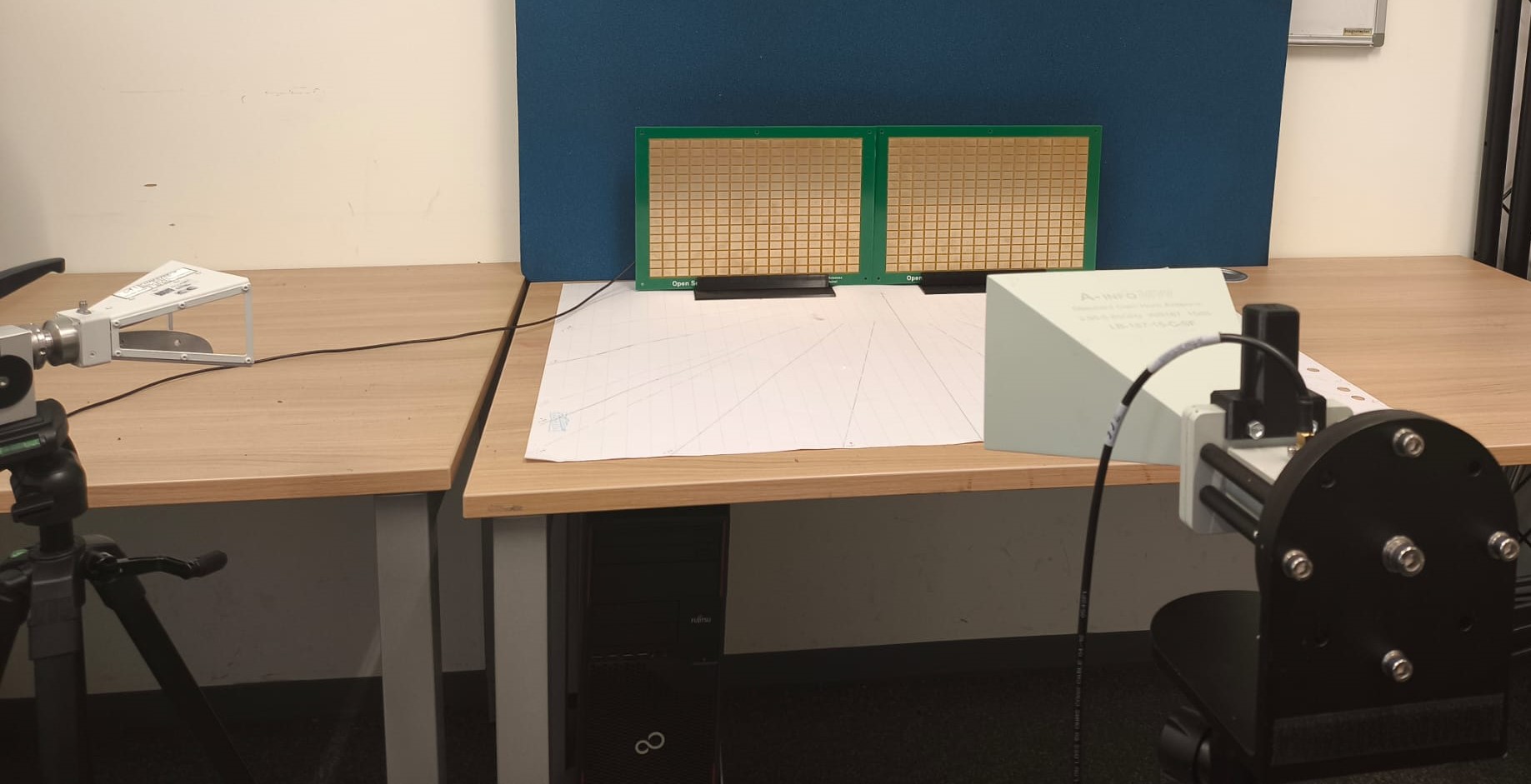
In Fig. 3, the experimental setup is shown, where ADALM-PLUTO software-defined radio (SDR) modules [2] are used with horn antennas for both the transmitter (UE) and the receiver (BS). Note that, unless otherwise specified, the two RISs are used and optimized as a single RIS. The two SDRs and RISs are all connected to a host computer and controlled using MATLAB and Python. The experimental configuration employs two RISs, each comprising elements with 1-bit phase control [6], with the UE transmission gain and BS receiving gain set to and , respectively. The system operates at in alignment with the optimum operating frequency of the used RIS [6]. A sampling frequency of is used to provide adequate time resolution for real-time signal processing while maintaining computational efficiency on the host computer. Horn antennas with gain are used at the BS and UE sides. Considering the indoor office environment, the BS–RIS and UE–RIS distances are set to and , respectively. The BCS length is set to to balance RIS switching speed constraints with sufficient correlation peak magnitude to exceed the noise floor by a noticeable margin, as shown in Fig. 5.
III-C Experiment Results
In this subsection, we report the experimental measurements for our proposed and baseline schemes. Specifically, we compare both schemes regarding the ASK modulation symbols they generate: the difference between the two amplitude levels. Furthermore, we implement the RIS-ID process at the BS side to measure the correlation amplitude associated with both schemes. Finally, to evaluate the resulting RIS-ID performance, two metrics are considered: the false alarm probability and miss-detection probability, , , respectively, where and is obtained using (9) when there is no transmission from the UE side [7]. In practice, the detection threshold and the BCS length can be obtained for a given , and can then be computed accordingly [7, Eqs. (14) and (22)].
In Fig. 4, we show the received signal amplitude levels for the proposed and baseline schemes, where it can be clearly seen that the proposed scheme achieves a remarkable performance gain in maximizing the amplitude difference between the two ASK symbols ( and ).
In Fig. 5, the correlation amplitudes measured at the BS side are shown, where the proposed scheme significantly outperforms the baseline across the measured angle range. This can be explained by the high passive beamforming gain achieved due to the phase adjustment using (6). In contrast, the baseline scheme exhibits specular reflection — reflecting the signal toward the angle equal to the incidence angle — due to the uniform phase adjustment, with no passive beamforming gain. Here, the average amplitude (normalized) achieved by the proposed and baseline schemes is and , respectively. This shows that the proposed scheme can provide much higher coverage for detecting the RIS, over a significantly wider range of UE and BS angular directions within the RIS FoV.


In Fig. 6, we consider the case of two different RISs (each with ), where a different BCS is assigned to each RIS module. Furthermore, each RIS module employs Algorithm 1 to enable its detection at the BS side by sweeping its FoV with the passive constructive/destructive beams according to its unique BCS. It can be seen that the proposed scheme outperforms the baseline by a significant margin with each RIS module.
In Fig. 7, we show and calculated based on different channel realizations, for statistical reliability. Here, as increases decreases while increases, which aligns with the theoretical results obtained in [7]. Furthermore, in terms of , the proposed scheme shows a clear performance gain over the baseline across the full range of , which aligns with the results in Figs. 5-6. Note that, due to the strong LoS link, a shorter BCS () is considered to induce miss-detection events. A similar performance is observed in Fig. 8, where the RIS-ID scheme enables RIS detection even in the absence of a LoS link, i.e., based solely on environmental reflections, which is not reported in [13].


IV Conclusion
In this work, we proposed a novel modulation scheme for the RIS-ID process that leverages the RIS’s high constructive/destructive passive beamforming, combined with passive beam sweeping, to reduce the miss-detection and false-alarm probabilities and widen the coverage area. The proposed modulation scheme has been validated through simulations and practical experiments, demonstrating a clear performance gain over the state-of-the-art baseline. The obtained results show a high potential for the proposed scheme to extend the detection coverage of RISs and make it more reliable.
References
- [1] (2020-Sep.) Intelligent reflecting surface: practical phase shift model and beamforming optimization. IEEE Trans. Commun. 68 (9), pp. 5849–5863. External Links: Document Cited by: §I, §I.
- [2] ([Online]. Available: https://wiki.analog.com/university/tools/pluto. Accessed: Sept. 26, 2025.) ADALM-PLUTO Overview. Analog Devices Wiki , pp. . Cited by: §III-B.
- [3] (2024-Sep.) Reconfigurable intelligent surfaces for 6G: emerging hardware architectures, applications, and open challenges. IEEE Veh. Technol. Mag. 19 (3), pp. 27–47. External Links: Document, ISSN 1556-6080 Cited by: §I.
- [4] (2020) Power scaling laws and near-field behaviors of massive MIMO and intelligent reflecting surfaces. IEEE Open J. Commun. Soc. 1, pp. 1306–1324. Cited by: §III-A.
- [5] (Oct. 2025) A novel partitioning scheme for RIS identification and beamforming. IEEE Wireless Commun. Lett. 15 (), pp. 245 – 249. Note: External Links: Document Cited by: §I.
- [6] () Open source reconfigurable intelligent surface for the frequency range of 5 GHz WiFi. In Proc. 2023 IEEE ISAP, pp. . Cited by: §III-B.
- [7] (Nov. 2025) A practical and simple detection and identification scheme for RIS-assisted systems. IEEE Open J. Commun. Soc. 6 (), pp. 9619–9631. Cited by: §I, §II-A, §II-B, §II-B, §III-C, §III-C.
- [8] (Dec. 2024) Two-stage channel estimation in mmWave MIMO systems with RIS blockage. IEEE Wireless Commun. Lett. 13 (12), pp. 3548–3552. External Links: Document Cited by: §II-A.
- [9] (May 2026) Joint channel estimation and blockage diagnosis in RIS-assisted mmWave MIMO-OFDM systems. IEEE Trans. Veh. Technol. 75 (5), pp. 8018–8029. External Links: Document Cited by: §II-A.
- [10] (2017) Synchronization in digital communication systems. Cambridge Univ. Press, Cambridge, U.K.. Cited by: footnote 1.
- [11] (2021-05) Reconfigurable intelligent surfaces: principles and opportunities. IEEE Commun. Surveys Tuts. 23 (3), pp. 1546–1577. External Links: Document Cited by: §I.
- [12] (June 2025) A comprehensive design framework for UE-side and BS-side RIS deployments. IEEE Wireless Commun. 32 (3), pp. 148–155. External Links: Document Cited by: §I.
- [13] (Oct. 2025) A practical validation of RIS detection and identification. IEEE Trans. Veh. Technol. 74 (10), pp. 16590 – 16594. Note: External Links: Document Cited by: §I, §I, §I, §II-B, §II-C, §III-A, §III-C.
- [14] (May 2019) Beamforming optimization for intelligent reflecting surface with discrete phase shifts. In Proc. IEEE ICASSP, Vol. , pp. 7830–7833. Cited by: §II-B.