Complex-Vector Power and Cross-Phase Unbalance in Three-Phase Systems
Abstract
Unbalanced three-phase systems still lack a compact phasor-domain representation of power that makes phase asymmetry explicit while remaining consistent with established apparent-power definitions. This paper addresses that point through a complex-vector power formulation for sinusoidal steady-state operation. The proposed representation supplements the classical dot-product expression of complex power with the cross product of voltage and current phasors, thereby retaining the usual active and reactive terms while making explicit a cross-phase unbalance vector that captures antisymmetric interphase relations. In this way, apparent power is separated into intraphase and cross-phase contributions, and its norm is preserved under the power-invariant Fortescue transformation. The formulation is extended to three-phase four-wire systems by introducing equivalent coordinates that preserve the effective apparent-power norm for the chosen voltage reference. Only standard complex numbers and matrices are required. Numerical examples show operating conditions in which a non-negligible part of the apparent-power structure is associated with cross-phase unbalance and cannot be inferred from active and reactive power alone. The proposed formulation thus provides a compact phasor-based descriptor of unbalance that complements established apparent-power theories by making explicit a component that is not accessible from scalar apparent-power representations.
I Introduction
Three-phase systems are meant to operate under balanced conditions, but real networks rarely do. Unequal single-phase loading, conductor asymmetries, and faults disturb the voltage and current sets and alter the way apparent power and power factor must be interpreted. In those situations, the conventional active and reactive power pair does not fully describe the structure of the electrical regime.
The method of symmetrical components, introduced by Fortescue [1, 2], remains the standard tool for analyzing unbalanced three-phase phasors. By splitting the system into positive-, negative-, and zero-sequence subsystems, it provides an effective description of asymmetry. This work deliberately focuses on sinusoidal steady-state unbalance. This is not intended as a simplification of the general power-quality problem, but as an isolation of one of its fundamental components: the description of apparent power when voltage and current phasors are asymmetric while waveform distortion is absent. Establishing a clear phasor-based formulation for this case is a necessary step before additional effects such as harmonic distortion or time-varying behavior are introduced.
Several established theories deal with apparent power under imbalance. Classical effective-apparent-power formulations such as the Fryze–Buchholz–Depenbrock (FBD) method [3], the Currents’ Physical Components (CPC) framework [4], and the practical line of work developed by Emanuel [5, 6, 7] and later reflected in IEEE Std. 1459–2010 [8] provide scalar measures and useful component decompositions. Other contributions have explored vector representations in the sinusoidal regime [9, 10, 11, 12], while broader algebraic approaches have extended the discussion to nonsinusoidal and multiphase settings [13, 14].
However, within the conventional sinusoidal phasor framework, these approaches do not simultaneously provide a compact quantity built directly from phasors that retains the classical complex-power interpretation, makes interphase antisymmetry explicit, and preserves the apparent-power norm under the power-invariant Fortescue transformation. This combined representation is the main focus of the present work.
To address this point, the paper introduces the Complex-Vector Power (CVP), obtained by complementing the classical dot-product expression of complex power with the cross product of voltage and current phasors. The dot-product term yields the usual active and reactive powers, whereas the cross product gives rise to a cross-phase unbalance (CPU) vector, interpreted not as a new physical form of power, but as a structural descriptor of interphase asymmetry that becomes explicit when the phase-domain voltage–current relation is considered as a whole.
The formulation remains fully within the standard phasor framework used in power-system analysis. No advanced algebraic machinery is required: the construction relies only on complex arithmetic and elementary matrix operations. This makes the approach directly compatible with conventional engineering practice while providing explicit information about cross-phase asymmetry that is not available from scalar apparent-power representations alone.
The CVP norm is preserved under the power-invariant Fortescue transformation, providing a consistent link between phase and sequence representations. Within this structure, apparent power can be written as the orthogonal combination of an intraphase contribution, associated with the dot-product term, and a cross-phase contribution associated with the CPU vector. The formulation is also extended to three-phase four-wire systems by introducing equivalent coordinates that preserve the effective apparent-power norm associated with the selected voltage reference, in agreement with IEEE 1459 in the sinusoidal steady-state regime.
The main contributions of this paper are therefore fourfold. First, it defines a Complex-Vector Power that combines the dot and cross products of voltage and current phasors in a single compact representation. Second, it identifies the cross-phase unbalance vector and clarifies its role as a structural descriptor of interphase asymmetry. Third, it proves that the CVP norm is invariant under the power-invariant Fortescue transformation. Finally, it extends the construction to three-phase four-wire systems through equivalent coordinates compatible with effective apparent power.
These contributions are developed progressively in the remainder of the paper. Section II introduces the CVP and formulates it for three-phase systems. Section III extends the approach to four-wire configurations. Section IV derives an instantaneous representation of the cross-phase term. Section V presents numerical examples, after which the main implications of the formulation are discussed and summarized.
II CVP in Three-Phase Systems
II-A Definition
In sinusoidal steady-state operation, voltages and currents in a three-phase system are represented by the phasor vectors
| (1) |
which, in this section, are assumed to be defined with respect to an arbitrary but fixed voltage reference; a specific choice is introduced only when the CVP is aligned with a particular effective apparent‑power definition, as discussed in Section III.
The classical complex power follows from the dot product
| (2) |
which aggregates intraphase active and reactive contributions. However, the dot product does not capture antisymmetric phase-to-phase relations between voltage and current phasors that arise when the system departs from balanced operation.
These relations are captured by the cross product of the phasors, which defines a cross-phase unbalance (CPU) vector
| (3) |
whose components are
| (4) |
The Complex-Vector Power (CVP) is defined by
| (5) |
The norm of the CVP satisfies the complex Lagrange identity (see Appendix A),
| (6) |
which establishes an orthogonal intraphase/cross-phase decomposition and defines an associated apparent-power magnitude. For balanced linear loads, the phasors are complex‑proportional ( with ), hence and the CVP reduces to the classical complex power.
The decomposition is consistent with the additive behavior of power at a common three-phase terminal. In particular, for parallel loads sharing the same phase voltages, both the dot-product term and the cross-phase term add linearly with the corresponding current contributions.
II-B Norm Preservation of CVP under Symmetrical Components
Since the CVP in (5) is defined in the phase domain, it is necessary to establish whether its properties are preserved when voltages and currents are expressed in a different coordinate system. For the analysis of unbalanced three-phase systems, the natural choice is the symmetrical-components (SC) transformation introduced by Fortescue.
Using the power-invariant form, the phase-domain phasors are mapped as
| (7) |
with
| (8) |
This matrix satisfies the power-invariance condition
| (9) |
which directly implies preservation of the dot product,
| (10) |
Consequently, the classical complex power —including contributions from positive-, negative-, and zero-sequence components—remains unchanged under the symmetrical-components transformation.
The cross product requires special attention, since it is not preserved under a general linear mapping. However, for the Fortescue matrix it can be shown that
| (11) |
Because and is unitary, the transformation preserves the norm of the cross component. As a result,
| (12) |
Although the orientation of the cross-phase component depends on the coordinate system, its norm remains unchanged (see Appendix B).
Since both the dot and cross components maintain their norms, the norm of the CVP is preserved,
| (13) |
From a geometric perspective, the dot product represents the intraphase projection of voltage and current phasors, whereas the cross product represents their antisymmetric interphase relation. The symmetrical-components transformation changes the coordinate representation but preserves the norms of both contributions, and therefore preserves the metric structure of the CVP.
In three-phase three-wire (3P–3W) systems, Kirchhoff’s current law forces the homopolar-sequence current to vanish (), yielding
| (14) |
However, a nonzero homopolar-sequence voltage may still exist; in such cases, although , the cross component generally retains a three-dimensional structure. A reduction to the plane occurs only under perfectly balanced voltages.
This possibility of dimensional reduction motivates the use of the symmetrical-components basis as an intermediate analytical space for extending the formulation to three-phase four-wire systems, addressed in the next section.
III Extension of the 3P–3W CVP to 3P–4W Systems
Three-phase four-wire (3P–4W) networks require an explicit and properly defined voltage reference, since the presence of a neutral conductor introduces an additional degree of freedom that is not naturally constrained by the three-dimensional CVP structure. While Kirchhoff’s current law limits the number of independent line currents to three, no analogous constraint exists for voltages in a four-terminal configuration; the reference must therefore be specified so as to satisfy a suitable compatibility condition.
Measurements at the point of common coupling (POC) provide the phase voltages
| (15) |
but these quantities depend on the adopted reference. To obtain a three-coordinate representation consistent with the CVP framework and with the effective-apparent-power formulation of IEEE 1459, the phase voltages are referred to an artificial (virtual) neutral defined by the generalized barycentric condition
| (16) |
with neutral-to-phase resistance ratio . This condition specifies the uniform shift that maps the measured line-to-neutral voltages onto the line-to- voltages,
| (17) |
where the shift follows explicitly as
| (18) |
This construction restores a three‑coordinate voltage representation compatible with the CVP framework.
The shifted voltages and line currents are then expressed in symmetrical components using the power-invariant Fortescue matrix ,
| (19) |
To ensure consistency with IEEE Std. 1459 under sinusoidal steady-state conditions, a metric correction is applied to the homopolar components within the CVP framework, defining the equivalent quantities
| (20) |
The resulting equivalent sequence vectors are
| (21) |
In these coordinates, the dot and cross components of the CVP retain their forms,
| (22) |
and the norm of the cross-phase unbalance component is preserved within the equivalent metric.
Applying the inverse transformation provides equivalent phase-domain phasors
| (23) |
which, in terms of the measured line-to-neutral phasors, admit the explicit expressions
| (24) |
where
| (25) |
To avoid ambiguity, we note that the subscript is used in two complementary ways: when attached to scalars (, , ) it denotes the effective rms quantities defined in IEEE 1459, whereas in vector form (, , ) it denotes the equivalent CVP coordinates whose norms reproduce those effective values in this regime.
These equivalents preserve the CVP metric and power structure:
| (26) |
| (27) |
Consequently,
| (28) |
Moreover, given that the equivalent voltage and current vectors have been constructed to match the corresponding effective rms quantities prescribed by IEEE 1459 in this regime, the equivalent apparent‑power norm likewise coincides, by construction, with the IEEE 1459 effective apparent power .
Limiting operating conditions
Balanced supply
If the supply is balanced, the artificial–neutral shift vanishes () and the homopolar‑sequence voltage is zero (). In 3P–4W systems, however, unbalanced loads may still give rise to a nonzero homopolar current () through the neutral. Since , this homopolar current component does not affect the dot‑product term , but still plays a role in the cross‑phase structure captured by .
Identical conductor resistances ()
The generalized barycentric condition reduces to the classical virtual-star-point condition of the FBD method [3]:
| (29) |
which implies the uniform shift
| (30) |
In the equivalent-phase construction one has .
Perfect neutral ()
The physical and artificial neutrals coincide (), hence and , . Although , the correction is immaterial because it multiplies a vanishing shift.
Three-phase three-wire ()
The artificial-neutral shift tends to the barycentric average
| (31) |
the homopolar current vanishes (), and . The formulation collapses to the standard 3P–3W model based on positive- and negative-sequence components.
IV Instantaneous Representation of the Cross-Phase Term
Consider a three-phase system operating under sinusoidal steady-state conditions, with instantaneous phase voltages and currents expressed with respect to the adopted POC reference. Although different reference choices would modify the numerical values of the phase quantities and the resulting cross-product terms, the algebraic structure of the CVP relations remains unchanged. The instantaneous voltages and currents are therefore written as
| (32) |
These instantaneous quantities define not only the scalar instantaneous power
| (33) |
but also the antisymmetric term
| (34) |
with
| (35) |
Its components are the antisymmetric combinations
| (36) |
an arrangement also considered in [15] from a different perspective.
Decomposing into mean and oscillatory parts,
| (37) |
each component of is a double-frequency sinusoid,
| (38) |
The amplitudes and phase angles are determined by the cross-product coefficients
| (39) |
where denotes any cyclic permutation of . Hence, these coefficients coincide with the components of the phasor cross product
| (40) |
i.e., the CPU term defined in Section II.
The vector therefore represents the amplitude and phase of the corresponding oscillatory terms, in parallel with Steinmetz’s observation that products of alternating quantities generate double-frequency components [16].
Since each has zero mean, its amplitude is characterized by its rms value,
| (41) |
Accordingly, the rms magnitude of the full cross-phase term is
| (42) |
Hence, the norm obtained from the phasor cross product is directly related to the rms magnitude of its instantaneous counterpart. The cross-phase term represents the antisymmetric inter-phase correlation between voltages and currents.
V Numerical Examples
This section presents two numerical examples illustrating the application of the proposed Complex-Vector Power (CVP) to three-phase four-wire systems under sinusoidal steady-state conditions. Each example reports the phase-domain phasors, the corresponding equivalent coordinates , the dot‑product term , the cross-phase vector , and the resulting apparent power and power factor (PF).
V-A Example 1 — Purely Reactive Asymmetric Load
Example 1 presents a conceptual configuration intended to illustrate the structural behavior of the proposed formulation under ideal conditions. A balanced three-phase source feeds a star-connected load composed of three purely reactive impedances expressed in per-unit with respect to a common reactance . The load neutral is directly connected to the source neutral. The per-unit system uses as the voltage base, as the current base, and as the base for all power components. In particular, the phase impedances are
| (43) |
The system is fed by balanced line-to-neutral voltage phasors
| (44) |
Since the supply is symmetrical, the artificial-neutral shift is zero (), and the phase voltages coincide with those referred to the virtual neutral.
Although each branch is purely reactive, the load is strongly asymmetric. The resulting phase currents are therefore unbalanced and produce a nonzero neutral current ().
The scalar powers satisfy
| (45) |
Although the total reactive power is zero, the individual phase contributions remain nonzero and cancel algebraically, while the cross-phase unbalance vector remains nonzero,
| (46) |
In this configuration, the CVP is entirely determined by the cross-phase term; consequently, the apparent power reduces to
| (47) |
This example illustrates that the apparent-power norm may remain nonzero even when the dot-product contribution vanishes, provided that the phase currents are not symmetrically distributed. Within the CVP framework, this residual apparent power is entirely associated with cross‑phase unbalance.
| Quantity | Example 1 |
|---|---|
| Power Component | Example 1 |
|---|---|
V-B Example 2 — Unbalanced supply with unequal load and conductor resistances
Example 2 considers a more realistic four-wire distribution configuration in which supply asymmetry, load unbalance, and unequal conductor parameters are simultaneously present, inspired by the circuit configuration discussed in [17, p. 175]. The system is modeled as a three-phase feeder with finite conductor impedances. The phase conductors have and mH, while the neutral conductor has the same inductance but a higher resistance , yielding .
The load consists of a strongly unbalanced line-to-neutral resistive set , , and , in parallel with a balanced delta-connected impedance . On the load side, the neutral conductor includes (Fig. 1).
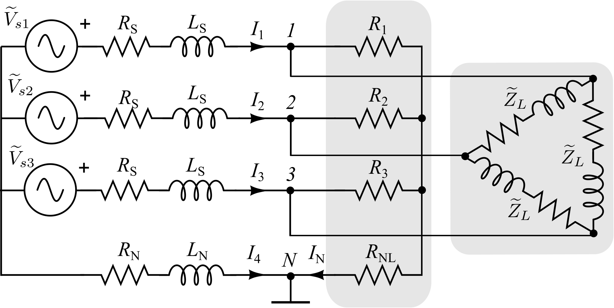
The source provides asymmetric 60-Hz line-to-neutral voltages. Using the artificial-neutral reference and the proposed equivalent coordinates, the resulting power quantities are consistent with the effective apparent-power definition prescribed in IEEE Std. 1459:
| (48) |
| (49) |
Computation in the modified symmetrical‑components domain yields identical dot‑product and cross‑product norms, confirming preservation of the CVP metric under the coordinate transformation. The resulting phasors and power quantities for Example 2 are reported in Tables III and IV.
| Quantity | Example 2 |
|---|---|
| Power Component | Example 2 |
|---|---|
| PF |
Discussion of Numerical Examples
The numerical examples show that cross-phase contributions can significantly affect apparent power under both balanced and unbalanced conditions, particularly in four-wire systems with asymmetric loads. In such cases, reactive power alone does not explain the observed power-factor reduction.
In Example 1, the apparent-power norm is entirely associated with the cross-phase term, with and . In Example 2, active, reactive, and cross-phase components coexist while preserving .
These results illustrate how the CVP formulation makes cross-phase effects explicit through while remaining consistent with standard apparent-power definitions.
VI Discussion
The proposed CVP provides a structured interpretation of three-phase apparent power by combining the conventional complex power with a cross-product term that captures interphase antisymmetry. Their norms satisfy
so the apparent-power magnitude is decomposed into intraphase and cross-phase contributions.
From an engineering viewpoint, the CVP clarifies sources of power-factor degradation in unbalanced systems. It can distinguish operating conditions with similar values of and but different internal phase structure, since part of the apparent-power norm may be associated with interphase asymmetry through . In such cases, reactive-power compensation alone does not necessarily address the full apparent-power demand. The proposed representation therefore assists the interpretation of unbalanced feeders, loads, and compensation strategies by separating intraphase phase-shift effects from cross-phase unbalance effects.
The cross-phase term also connects with the instantaneous picture: determines the amplitudes and phases of the associated oscillatory components, and its norm relates to their rms magnitude. This is consistent with classical observations that products of sinusoidal quantities generate double-frequency terms [16]. The present formulation expresses these phase relationships through conventional complex arithmetic, without requiring additional algebraic machinery.
Another point made explicit by the CVP is the role of the voltage reference in apparent-power representations. The algebraic values and orientation of depend on that choice, whereas its norm is preserved under the power-invariant Fortescue transformation. Thus, the internal structure of the representation is reference sensitive, while the associated apparent-power metric remains well defined, in agreement with previous discussions on voltage reference selection [19, 20].
For three-phase four-wire systems, the equivalent-coordinate construction introduced in Section III provides a consistent way of working within a three-coordinate setting without losing the effective apparent-power norm. This allows the CVP to remain compatible with IEEE 1459 in the sinusoidal steady-state regime while preserving the same multicomponent structure used in the three-wire case.
The present formulation is developed for sinusoidal unbalanced conditions; harmonic distortion, nonlinear loads, and time-varying regimes are outside its scope.
Relation to IEEE 1459 unbalance power
Under sinusoidal steady-state conditions, IEEE 1459 defines . In the CVP formulation,
The two decompositions are therefore consistent at the level of the effective apparent-power norm, but they differ in structure. IEEE 1459 defines the unbalance power with respect to the positive-sequence apparent power, thereby aggregating different effects of asymmetry into a scalar quantity. In contrast, the CVP separates the total phase-domain interaction into an intraphase contribution, represented by , and an explicitly interphase contribution, represented by .
Accordingly, does not in general coincide with . Rather than replacing IEEE 1459 quantities, the CVP complements them by making explicit the cross-phase contribution that remains implicit in scalar apparent-power descriptions.
Importantly, the CVP does not postulate a new energetic carrier or an additional physical kind of power. The cross-product term should be interpreted as a structural descriptor of how the voltage–current relation is distributed across phases under unbalanced conditions. In this sense, the CVP does not redefine the physical mechanisms of energy transfer, but makes explicit a component of the phase relations that is not accessible from scalar apparent-power representations.
VII Conclusions
This work introduces the Complex-Vector Power (CVP) as a phasor-based formulation for sinusoidal unbalanced three-phase systems. By extending the classical complex power with a cross-product term, the approach makes cross-phase unbalance explicit while preserving the apparent-power norm.
The CVP norm satisfies the complex Lagrange identity and is preserved under the power-invariant Fortescue transformation, providing a consistent link between phase and sequence representations. The formulation also extends to three-phase four-wire systems through equivalent coordinates compatible with effective apparent power.
From a practical perspective, the CVP helps interpret cases where apparent power and power-factor degradation cannot be attributed to reactive power alone. The cross-product term should therefore be understood as a structural descriptor of interphase unbalance embedded in the voltage–current relation, rather than as an additional physical power mechanism.
Appendix A Lagrange’s Identity in Complex Form
Let be complex vectors endowed with the Euclidean norm . Lagrange’s identity in complex form reads
| (50) |
This product can be decomposed as
| (51) |
To see this, note that
| (52) |
Rearranging terms yields
| (53) | ||||
Finally,
| (54) |
This identity provides the mathematical basis for decomposing the norm of the Complex‑Vector Power into dot‑ and cross‑product contributions.
Appendix B Dot and Cross Products under the Fortescue Transformation
For completeness, this appendix derives the relations between the phase-domain quantities and their symmetrical components that support the norm-preservation properties of the CVP discussed in the main text.
B-A Symmetrical Components
Let the phase-domain current vector be
| (55) |
The symmetrical components are obtained through the power-invariant Fortescue transformation
| (56) |
Explicitly,
| (57) | ||||
| (58) | ||||
| (59) |
and the same relations apply to the voltages. Since is invertible,
| (60) |
B-B Dot Product
The dot product in symmetrical coordinates is
| (61) |
Using and , a direct expansion yields
| (62) |
Hence, the dot-product contribution to the CVP is preserved under the Fortescue transformation.
B-C Cross Product
Unlike the dot product, which is preserved under unitary transformations, the cross product is not generally preserved under linear mappings and must therefore be evaluated explicitly.
The cross product in symmetrical components is
| (63) |
Expressing these terms in phase coordinates and grouping yields
| (64) |
Since
| (65) |
the transformation can be written compactly as
| (66) |
B-D Consequence: Invariance of the Norm
Because and is unitary,
| (67) |
Thus, the norm of the cross‑phase component of the Complex‑Vector Power is preserved under the Fortescue transformation.
References
- [1] C. L. Fortescue, “Method of symmetrical co-ordinates applied to the solution of polyphase networks,” Proc. Amer. Inst. Electr. Eng., vol. 37, no. 6, pp. 629–716, Dec. 1918.
- [2] C. L. Fortescue, “Polyphase power representation by means of symmetrical coordinates,” Trans. Amer. Inst. Electr. Eng., vol. 39, pp. 1481–1484, 1920.
- [3] M. Depenbrock, “The FBD-method, a generally applicable tool for analyzing power relations,” IEEE Trans. Power Syst., vol. 8, no. 2, pp. 381–387, 1993.
- [4] L. S. Czarnecki, “Currents’ physical components (CPC) in circuits with nonsinusoidal voltages and currents. Part 2: Three-phase three-wire linear circuits,” Electr. Power Qual. Util. J., vol. 12, no. 1, pp. 3–13, 2006.
- [5] A. E. Emanuel, “On the definition of power factor and apparent power in unbalanced polyphase circuits with sinusoidal voltage and currents,” IEEE Trans. Power Deliv., vol. 8, no. 3, pp. 841–852, 1993, doi: 10.1109/61.252612.
- [6] A. E. Emanuel, “The Buchholz-Goodhue apparent power definition: The practical approach for nonsinusoidal and unbalanced systems,” IEEE Trans. Power Deliv., vol. 13, no. 2, pp. 344–348, 1998.
- [7] A. E. Emanuel, “Apparent power definitions for three-phase systems,” IEEE Trans. Power Deliv., vol. 14, no. 3, pp. 767–772, 1999.
- [8] IEEE Standard Definitions for the Measurement of Electric Power Quantities Under Sinusoidal, Nonsinusoidal, Balanced, or Unbalanced Conditions, IEEE Std. 1459–2010, Mar. 2010.
- [9] V. León-Martínez, J. Montanãna-Romeu, A. Cazorla-Navarro, J. Giner-Garcia, and J. Roger-Folch, “Phasor total unbalance power: Formulation and some properties,” in Proc. IEEE Instrum. Meas. Technol. Conf. (IMTC), 2007, pp. 1–6.
- [10] J. M. Diez, P. A. Blasco, and R. Montoya, “Formulation of phasor unbalance power: Application to sinusoidal power systems,” IET Gener. Transm. Distrib., vol. 10, no. 16, pp. 4178–4186, 2016.
- [11] V. León-Martínez and J. Montanãna-Romeu, “Formulations for the apparent and unbalanced power vectors in three-phase sinusoidal systems,” Electr. Power Syst. Res., vol. 160, pp. 37–43, 2018.
- [12] P. A. Blasco, R. Montoya-Mira, J. M. Diez, and R. Montoya, “An alternate representation of the vector of apparent power and unbalanced power in three-phase electrical systems,” Appl. Sci., vol. 10, no. 11, Art. no. 3756, Jun. 2020, doi: 10.3390/app10113756.
- [13] H. Lev-Ari and A. M. Stanković, “Instantaneous power quantities in polyphase systems—A geometric algebra approach,” in Proc. IEEE Energy Convers. Congr. Expo. (ECCE), 2009, pp. 592–596.
- [14] F. G. Montoya, J. Ventura, A. Alcayde, and F. M. Arrabal-Campos, “Geometric power theory in the frequency domain for non-sinusoidal and unbalanced multiphase AC systems,” Int. J. Electr. Power Energy Syst., vol. 165, Art. no. 110454, 2025, doi: 10.1016/j.ijepes.2025.110454.
- [15] F. Z. Peng and J.-S. Lai, “Generalized instantaneous reactive power theory for three-phase power systems,” IEEE Trans. Instrum. Meas., vol. 45, no. 1, pp. 293–297, 1996.
- [16] C. P. Steinmetz, “Symbolic representation of general alternating waves and of double frequency vector products,” AIEE Trans., vol. XVI, pp. 269–296, 1899.
- [17] A. E. Emanuel, Power Definitions and the Physical Mechanism of Power Flow. Hoboken, NJ, USA: Wiley–IEEE Press, 2011.
- [18] A. I. Petroianu, Bridging Circuits and Fields: Foundational Questions in Power Theory. Boca Raton, FL, USA: CRC Press, 2021.
- [19] J. L. Willems and J. A. Ghijselen, “The relation between the generalized apparent power and the voltage reference,” in Proc. 6th Int. Workshop on Power Definitions and Measurements under Nonsinusoidal Conditions, Milan, Italy, Oct. 13–15, 2003, pp. 37–45.
- [20] V. León-Martínez, J. Montañana-Romeu, E. Peñalvo-López, and C. M. Álvarez-Bel, “Effects of the selected point of voltage reference on the apparent power measurement in three-phase Star Systems,” Appl. Sci., vol. 10, no. 3, Art. no. 1036, 2020, doi: 10.3390/app10031036.