Automating Execution and Verification of BPMN+DMN Business Processes
Abstract
The increasing and widespread use of BPMN business processes, also embodying DMN tables, requires tools and methodologies to verify their correctness. However, most commonly used frameworks to build BPMN+DMN models only allow designers to detect syntactical errors, thus ignoring semantic (behavioural) faults. This forces business processes designers to manually run single executions of their BPMN+DMN processes using proprietary tools in order to detect failures. Furthermore, how proprietary tools translate a BPMN+DMN process to a computer simulation is left unspecified. In this paper, we advance this state of the art by designing a tool, named BDTransTest providing: i) a translation from a BPMN + DMN process to a Java program ; ii) the synthesis and execution of a testing plan for , that may require the business designer to disambiguate some input domain; iii) the analysis of the coverage achieved by the testing plan in terms of nodes and edges of . Finally, we provide an experimental evaluation of our methodology on BPMN+DMN processes from the literature.
keywords:
BPMN processes , DMN tables , Business Processes Verification[univaq]organization=Department of Information Engineering, Computer Science and Mathematics, University of L’Aquila, addressline=Via Vetoio 1, city=L’Aquila, postcode=67100, country=Italy
1 Introduction
Since its first release dating back to 2004, Business Process Model and Notation (BPMN) [36, 22] has gained an ever-increasing importance in modeling business processes in companies all around the world [9, 39]. As an example, BPMN.iO reports nearly 8000 currently active BPMN projects per week, and there exist tens of publicly available repositories maintaining thousands of BPMNs each.
Starting from 2015, the Decision Model and Notation (DMN) [37, 13] has been designed to complement BPMN on decision making, by providing a graphical notation and an expression language to describe in a non-specialistic way possibly complex Boolean formulas. Also in this case, usage of the BPMN+DMN combo has been high since the first beginning, and is currently growing [23, 24].
Unfortunately, as is common with any type of “programming”, it is rather easy to make errors when describing a business process using BPMN and DNM notations. However, the most commonly used frameworks to build BPMN+DMN models (e.g., Camunda 111https://camunda.com/) only allow the designer to detect syntactical errors. This excludes the various types of semantic faults that a BPMN+DMN model can be tampered with: unexpected behaviors, nontermination, unreachable BPMN blocks, and so on. Furthermore, even the simple “execution” of a given BPMN+DMN could be not easy, as it is typically required to use some proprietary framework (e.g., again Camunda) which only allows one execution at a time and does not provide details about the inner translation from BPMN+DMN to a software process.
To the best of our knowledge, there are no works in the literature that tackle the problem of automatically translating a given business process, described using BPMN and DMN notations, into a software process in such a way that the software code can be inspected by a software engineer. Furthermore, while many works in the literature address the problem of verifying a BPMN business process, the verification of a given business process, described using both BPMN and DMN notations, has attracted less attention (see Section 2).
In this paper, we show how both obstructions outlined above may be tackled together. Namely, we achieve the following contributions.
-
1.
We describe an automated translation from a BPMN+DMN process to a Java program . This allows both static inspection of by an expert and framework-free execution of by using . We point out that the translation algorithm has been developed in a modular way, thus the usage of Java as the target language may be easily replaced by any other imperative programming language where all the BPMN and DMN features (most notably, parallelism) can be achieved or simulated.
-
2.
The translation described in the previous point also detects all inputs of with the corresponding domains. That is, we are able to detect which variables in the input business process are expected to receive a value from the outside environment.
-
3.
For most business processes , starting from the list of the inputs of from the previous point, we automatically synthesize and execute a testing plan for . Such testing plan selects in a guided random way the values for each input and then executes on such values. Our methodology allows the user to choose between different types of testing plans, e.g., with a fixed number of iterations or using statistical model checking. For business processes involving complex decisions, further disambiguating inputs from the user is required in order to perform the verification.
-
4.
We analyze the results of the testing phase described in the previous point, in order to compute the coverage achieved, both in terms of nodes and edges of .
-
5.
We present the BDTransTest tool, available at https://github.com/gdellapenna/BPMNModelTranslator, which implements the methodology described above. An overview of the BDTransTest tool is shown in Figure 1.
-
6.
Finally, we evaluate our BDTransTest tool on BPMN+DMN processes from the literature.
The rest of the paper is organized as follows. Section 2 describes the state-of-the-art on BPMN+DMN execution and verification from the literature. Section 3 provides the technological and theoretical background needed to understand this paper. Section 4 describes in detail how the translation from a BPMN+DMN business process to a Java program is performed (corresponding to contributions 1 and 2 discussed above). Section 5 shows how such translation is exploited to perform thorough testing of the input BPMN+DMN business process (corresponding to contributions 3 and 4 discussed above). Section 6 presents experimental results on using our approach on two case studies from the literature. Section 7 concludes the paper with final remarks and future developments.

2 Related Work
Our main goal is verification of BPMN+DMN processes, thus we organize our literature review by first discussing the (not many) papers addressing the very same problem, then we also examine some works dealing with verification of BPMN only and DMN only.
In [15], a process described by BPMN and DMN is translated into a Data Petri net. This allows to exploit verification techniques for Data Petri nets to verify BPMN properties like data-aware soundness, as well as arbitrary temporal formulae expressing requirements on both the control-flow and data. In this work, we do not rely on an intermediate formalism like Data Petri nets, but we translate the BPMN+DMN process in an executable program in order to directly apply testing techniques. We also note that our approach does not have the limitations of [15], e.g., we are able to fully handle integer variables and arithmetic operations. In [5], the authors propose an extension of the BPMN engine Camunda which allows to test processes described by BPMN and DMN, by also requiring in input a set of paths of the given BPMN and a database of test cases to be customized. In our approach, we lift such limitations, by only requiring in input a BPMN+DMN process (possibly with disambiguations for complex DMNs) and by only relying on a JVM for execution. In [1], the reverse problem is considered of using BPMN+DMN to enable Systems Modeling Language (SysML) to perform verification, in the form of requirements traceability. Instead, in this paper we focus on BPMN+DMN verification. Finally, in [29], a survey is presented that discusses the challenges that emerge when modeling, executing, and monitoring IoT-driven business rules using BPMN 2.0 and DMN standards.
As for literature on verifying a given BPMN without DMN, we may consider the following papers. In [20], a review of the current state-of-the-art on BPMN direct execution (thus supporting also verification) is carried out, showing that very few vendors currently support the full BPMN 2.0 standard. In [17], methodologies borrowed from Model-Driven Engineering are used to translate a BPMN into a Petri Net, that is then executed and verified within the DENEB workflow. In [40], a methodology is proposed to refactor a given BPMN, in order to reduce quality faults, such as unmeaningful elements, fine-grained granularity or incompleteness. In [12], a formalization and a tool are proposed for the animated execution of BPMN collaborations. In [45], a modelling approach is proposed that uses standard BPMN concepts to model Internet of Things (IoT)-enhanced business processes without modifying its metamodel, so as to facilitate the execution of the IoT-enhanced business processes independently from IoT devices technology. In [35], a methodology is proposed to find defects of flows in SAP business processes with a Machine-Learning approach. In [27], a three-step approach is proposed that incrementally refines a critical system specification, from a lightweight high-level model targeted to stakeholders, down to a formal standard model that links requirements, processes and data. In [2], the given BPMN is executed using existing frameworks, and an analysis of the resulting logs is performed in order to detect properties like absence of deadlocks and livelocks, as well as of dead elements. In [6, 7], a tool is developed that covers three main aspects of verifying a BPMN: a static verification, an interactive execution, and an automatic exploration of the possible scenarios. In [32], a Web application is designed that takes as input BPMN-2.0-compliant business processes. The processes are first translated into model-specific verification scripts in the SVL [19] verification language. Then, the verification toolbox CADP [19] is used to check either for functional properties. In [30], a methodology is proposed to build a knowledge-based for construction process reengineering by templates, rules and patterns in order to verify, validate and modify configured process models. Petri Nets method is selected for the verification and validation purpose. In [33], the Business Process Evaluation and Research Framework for Enhancement and Continuous Testing (bPERFECT) framework is proposed, which aims to guide business process testing research and implementation. Secondary objectives include eliciting the existing types of testing, evaluating their impact on efficiency and assessing the formal verification techniques that complement testing. In [28], an approach is presented that allows stakeholders and software analysts to merge and integrate behavioral and data properties in a BPMN model. To this aim, a lightweight BPMN extension is proposed that specifically addresses the annotation of data properties in terms of constraints, i.e., pre- and post-conditions that the different process activities must satisfy. In [31], a tool is designed that identifies control flow errors in BPMN models, make them understandable for modelers, and suggest corrections to resolve them. In [34], the input BPMN is transformed to the topological functioning model in order to check completeness of inputs, outputs and functioning cycles of the entire specified system. The proposed approach is dedicated to the verification of the model at the beginning of analysis, and it could be supplemented by other methods at the design stage. In [18], a Java based verification approach is proposed for Business Processes modeled using the BPMN 2.0 standard. The behavior of a set of interrelated objects, corresponding to a BPMN 2.0 specification, are explored by means of a verification algorithm using an ad-hoc unfolding technique. In [44], it is shown how to apply reachability and coverability analysis of Petri Nets to verification of business processes with transactions and compensation. In [11], a verification approach is presented for BPMN collaborations. It combines both standard model checking techniques, through the MAUDE [3] LTL model checker, and statistical model checking techniques, through the statistical analyzer MultiVeStA [46]. In [16], a hierarchical verification technique is proposed for the state space analysis of a BPMN based on a colored Petri Nets (CPN). A BPMN partitioning technique and rules for the transformation of a BPMN into a CPN model are provided. The partitioning approach supports the unstructured BPMN design model, and the obtained CPN model also supports hierarchical verification. In [43], a model checker based framework is presented to automate the verification process of a BPMN. To this aim, the BPMN is automatically converted into PROMELA, the input language of the SPIN model checker. Furthermore, the tool eases the task of expressing Linear Temporal Logic correctness requirements. In [26], a formal semantics is proposed for a subset of BPMN. In contrast to transformational approaches, which give a semantics to BPMN by mapping it to some formal model (e.g., Petri nets), this approach is based on a direct formalization in first-order logic that is then realized into the TLA+ model checker input language.
Finally, some work only considers DMN tables, without their BPMN environment. Namely, in [21] a review is presented of tools allowing the verification of DMN tables, while in [10] a survey of the most common errors (e.g., missing rules) in modeling DMN tables taken from large datasets is discussed.
Summing up, to the best of our knowledge, this paper is the first to propose an automatic approach to the translation, execution and testing of a business process described using BPMN and also employing DMN tables.
3 Background
In this section, we provide the main notions needed to understand the rest of the paper, by describing the fundamentals of the Friendly Enough Expression Language (FEEL) language (Section 3.1), of BPMN (Section 3.2) and of DMN (Section 3.3).
3.1 FEEL Language
FEEL is a language designed to express simple expressions in a way that is easily understood by both professionals and developers [38]. It has been specified by the Object Management Group (OMG) and can be used in both BPMN and DMN to write expressions where required.
Namely, FEEL allows to build intuitive expressions of the following types: String, Numeric, List, Context, Temporal and Boolean. String type contains any sequence of characters between double quotes, also allowing concatenation between strings. Numeric type includes both integer and real numbers, and allows the standard mathematical operations (e.g., addition and multiplication) as well as some standard functions, e.g., abs, floor, sqrt, etc. Temporal type allows to specify dates and times, and allow time-based arithmetical operations (e.g., time("08:00:00") + time("04:00:00")). List type contains order sequences in square brackets, allowing dereferentiation of one or multiple list elements (e.g., [1,2,3,4][item > 2] returns [3,4], while [1,2,3,4][2] returns 2). Context types are similar to Python dictionaries, e.g., {a: "bye", b : 2}. Boolean expressions atomic proposition involve comparisons between the above defined types (e.g., v <= 3, s = ”Hi”, time("04:00:00") <= time("08:00:00")), null checks, type tests (e.g., 1 instance of string is false, "1" instance of string is true), list memberships (e.g., 1 in [1, 3, 5] is true) and so on. Of course, the main Boolean operators (NOT, AND, OR) are also available. Finally, ranges may be build using the numeric and the temporal types, e.g., [3..10], also allowing operators to check for overlapping, inclusion and so on (e.g., overlaps before([1..5], [4..10]) is true).
3.2 BPMN Notation
Figure 2, adapted from [15] and that we use for reference in the following, shows an example of BPMN business process. A BPMN process is an annotated and labeled graph where nodes and edges may have different types, resembling a control flow diagram.
A number of variables may be used within each BPMN process; usage of a variable include both simply reading its current value (e.g., as in the pLength = -1 check in Figure 2, that reads variable pLength) or modifying its current value by writing a new value (e.g., as in the “get length” box in Figure 2, which writes a new value into variable
t pLength, also see discussion below).
Namely, main node and edge types are the following (Section 4.9 discusses the few BPMN elements we do not consider here):
-
1.
start events, depicted as circle-shaped, are the entry points of the whole process, i.e., they have no ingoing edges and one outgoing edge; in Figure 2, the start event is the “package received” node;
-
2.
end events, depicted as bold-circle-shaped, are the exit points of the whole process (i.e., they have no outgoing edges and one ingoing edge) and are typically distinguished as correct end events (“ready for shipment” in Figure 2) and error end events (also containing a bolt, see “undefined length”, “unsupported weight” and “no shipment” end events in Figure 2);
-
3.
tasks, depicted as rounded-edges rectangles and having exactly one ingoing and one outgoing edge, describe some action to be taken, such as the “get length”, “measure weight”, “determine mode” and “choose consent” tasks in Figure 2. Several types of task exist. Here, we focus on those which may change the value of a variable, i.e., user tasks (depicted with an avatar figure, see “measure weight” task in Figure 2), manual tasks, script tasks, service tasks and business rule tasks (depicted with a table as they are linked to a DMN table, see Section 3.3). Namely, user tasks and manual tasks may assign to a variable the value decided from an external user. Instead, script, service and business rule tasks may assign to a variable the value of a given FEEL expression and of a DMN table, respectively. We will also consider send tasks and receive tasks, which allow to send and receive messages when a BPMN process is divided in concurrent threads of execution;
-
4.
gateways, depicted as a diamonds, represents points in which some choice must be done; they can be further divided as follows:
-
(a)
exclusive gateways, where the diamond contains a cross, have one incoming and multiple outgoing edges. Such outgoing edges are labeled with FEEL Boolean expression, so that the first edge evaluating to true is executed. There are 4 of such gateways in Figure 2, where a crossed edge identifies the default case;
-
(b)
parallel gateways, where the diamond contains a plus sign, and inclusive gateways, where the diamond contains a circle, both have one incoming and multiple outgoing edges. Inclusive gateways outgoing edges again have Boolean FEEL conditions, while parallel gateways does not. Differently from the preceding case, all edges (for parallel gateways) and all edges evaluated to true (for inclusive gateways) are concurrently executed;
-
(c)
joining gateways have multiple incoming and one outgoing edges, and are meant for re-join of different path which were split before (the symbol inside the diamond is either a cross, a plus or a circle, depending on what it is re-joining): there is one such gateway in Figure 2;
-
(a)
-
5.
annotations, depicted as rectangles and labeled with a variable, indicate which task or event read and/or writes the corresponding variable: outgoing dotted edges to tasks represent a read access, ingoing dotted edges from tasks represent a write operation (there are 5 such annotations in Figure 2).
As for the BPMN representation as a file, in this paper we will refer to the XML encoding used by many BPMN editors like Camunda. Such encoding uses a predefined XML schema to represent all BPMN elements (tasks, events, gateways, annotations for variables…) listed above. Furthermore, we assume to have a function extractGraph which takes a BPMN representation and returns the underlying graph, in which annotations are discarded and node/edge types are not distinguished (see Figure 3 for the graph extracted from Figure 2). Finally, we note that BPMN also allows tasks with more than one outgoing edge; in the following, we suppose that BPMN processes are preprocessed so as to add exclusive gateways after such tasks as shown in Figure 4 (such preprocessing is actually performed also in our implementation tool BDTransTest).
3.2.1 Variables in BPMN Processes
As discussed above, user and manual tasks, as well as start events, may involve a write operation on a variable which is decided by an external user, while script and business rule tasks may write a variable basing on the BPMN process itself. To highlight such behaviour, we will call input variables those which are written by start events, user tasks or manual tasks, while we call process variables the other ones. We note that, strictly speaking, a variable in a BPMN process may be both an input variable and a process variable, e.g., if it is written both by the start event and by a business process rule (e.g., suppose that “get length” business rule task in Figure 2 writes pType again, instead of pLength). This however entails a re-usage of variables which could hamper BPMN readability and lead to programming errors, as it happens with variables re-usage in high-level programming languages. For this reason, we pre-process the input BPMN process to detect variables which are both input and process variables, so that the process engineer may re-name such variables. We also note that such pre-process may be valuable to find some early errors in the BPMN process.
Furthermore, if a BPMN process is drawn at an early process development stage, it may not correctly specify write operations on variables. As an example, in a first draft for the Shipment BPMN process in Figure 2, the annotation for pType may be omitted, and variable pType may be directly read inside the DMN “get length”. In order to capture this behaviour, also such only-read-and-never-written variables are considered input variables.


3.3 DMN Notation
Figures 5–7, again adapted from [15], show 3 examples of DMN tables used within a BPMN business process (the same depicted in Figure 2). Each of such tables is linked with a BPMN task; a task embodying a DMN table is called a business rule task. As an example, the DMN table in Figure 5 is linked to the “get length” business rule task in Figure 2, as well as DMN tables in Figures 6 and 7 are linked to business rule tasks “determine mode” and “choose consent”, respectively. The link between a DMN table and the corresponding business rule task also specifies how arguments are passed, i.e., how the BPMN process variables maps into the DMN variables or expressions used in the header row.
Figure 8 shows the generic form of a DMN table. Namely, such table is composed, from left to right, by at least one input column and at least one output column, with a double vertical line separating inputs and outputs (in some editors, also different colors are used). A final column may be used to hold some annotations. The first (header) row of a DMN table labels each input/output column with a variable occurring in the corresponding BPMN. The other rows contain, in the input part, either constant values or ranges in the domain of the corresponding FEEL expression, or a fixed value in the domain of the corresponding output column variable. Namely, each row represents a conditional assigment to all output column variables, depending on the input columns to fulfill the corresponding FEEL conditions shown in the same row. In the following, for the sake of clarity, we assume to employ the first policy, i.e., if more than one row is satisfied by the current input variables values, the first row is selected. However, our BDTransTest tool is also able to handle other policies, i.e., the “unique” policy and the “any” policy.
In Figure 8, the first group of columns refer to the table input variables (), the second group to output variables (), and is the content, as a FEEL expression, of DMN cell . To define the formal semantics of such generic DMN table, let be true iff the value of input variable corresponding to input column satisfies . Since may contain either a value or a range , is true if in the first case, and if in the second case. Note that, in the input columns, a dash means “don’t care”, in which case is always true. Given this, the semantics of such table is an AND between implications involving input and output variables of each row. More in detail, the semantics of the generic DMN table in Figure 8 is the Boolean formula:


| … | … | ||||
| … | … | ||||
| ⋮ | ⋮ | ⋮ | ⋮ | ⋮ | ⋮ |
| … | … | ||||
| - | - | - | … |
4 From BPMN and DMN to (Java) Code
In this section, we describe the first part of our BDTransTest tool, i.e., the algorithm which takes as input a BPMN process (possibly referencing DMN decision tables) and outputs a set of Java classes. By executing the main of such classes with a given assignment to BPMN variables, the same trace is returned which results from executing the input BPMN. From now on, we will refer to such algorithm as BDTrans, as depicted in Figure 1.
The rest of this section is organized as follows. Section 4.1 introduces the main auxiliary routines and libraries used by BDTrans. Section 4.2 explains the overall high-level organization of BDTrans. Section 4.3 details the translation of the main tasks, events and gateways of a BPMN. Section 4.4 shows how DMN tables are translated, and Section 4.5 shows how they are linked to the main BPMN. Section 4.6 deals with BPMN tasks containing send/receive message operations. Section 4.7 shows an example of a complete translation of BPMN process into a Java code. Section 4.8 discusses the main implementation details of the translation inside our BDTransTest tool. Section 4.9 discusses the current limitations of our approach. Finally, Section 4.10 shows that BDTrans behaves correctly.
4.1 BDTrans Auxiliary Functions and Libraries
The Java classes output by BDTrans rely on an execution framework, called BPMNExecutionLayer (BeL for short in the following figures), which hides all language-specific library calls and structures, leaving the generated code as clean and easy to read as possible. As an example, such framework includes classes to maintain the current status of a process execution, to retrieve the input values for BPMN variables, to output the execution trace, to perform comparisons between BPMN variables and so on.
Furthermore, BDTrans also includes an auxiliary subroutine FEEL2Java that is able to translate a generic FEEL expression to Java code, by also relying on the BeL framework. Namely, given a FEEL expression , FEEL2Java first considers the abstract parse tree of . Then, the translation is performed top-down, from the root to the leaves, by using the most suitable Java type for each FEEL type (e.g., the Boolean FEEL type is cast into the boolean Java type) and the most suitable Java operator for each FEEL operator (e.g., the FEEL plus sign can be translated in the Java plus sign both for numbers and strings). This also entails calling Java functions when needed, e.g., to translate the abs or the length FEEL functions, or to map the equality sign to equals Java function.
4.2 Overall BDTrans Organization
In the following, we will refer to the input of BDTrans as a pair , where is a BPMN and is a (possibly empty) set of decision tables linked to .
Given this, the overall structure of BDTrans is described in Algorithm 1. Namely, function BDTrans first analyzes all annotations and all FEEL expressions used in the BPMN, i.e., in tasks, gateway conditions, and decision table rules, and derives the process and input variables of (line 2, see also Section 3.2.1). As an example, for the Shipment BPMN process in Figure 2, the following variables are identified: pType, pWeight, consent, pLength, sMode. Of such variables, pType and pWeight are the input variables, as they are written by the start event and the “measure weight” user task, respectively; the other ones are process variables. Furthermore, for each of such variable, the corresponding domain is also derived. Namely, comparisons with fixed FEEL constants are used to derive the correct Java type to be used; e.g, if the FEEL expression v < 3.5 occurs somewhere in the input BPMN, then variable v will be declared as Double. Both variable names and their Java types are collected in the returned sets (for input variables) and (for process variables), which are then used by the routines for DMN and BPMN translation. Namely, both and contains triplets , where is a variable, its Java type (Integer, Double, String etc.) and contains information needed by BDTest, thus it will be explained in Section 5.1.
After this, BDTrans detects all DMN tables in the input DMN , and separately translates each of them into three Java classes via function translateDMN (line 3). Formal details of such translation are provided in Section 4.4. Then, a further Java class is generated by auxiliary function translateBPMN (detailed in Algorithm 2 and discussed in Section 4.3) for the input BPMN in line 4. Finally, such class is returned in line 5, together with the other two outputs shown in Figure 1, i.e., the set of input variables returned by getVarsDoms, and the underlying graph of (obtained by invoking extractGraph, already mentioned in Section 3.2).
4.3 Overall BPMN Translation
To better illustrate how function translateBPMN in Algorithm 2 works, consider the generic overall BPMN process GenericBPMN in Figure 9. Note that, in the following figures, for sake of generality we shall indicate with a cloud symbol (which cannot be confused with an actual BPMN element) a generic sub-diagram such that its last element is not an exclusive, a parallel or an inclusive gateway. We also denote the starting and ending BPMN tasks of with and , respectively. Therefore, the GenericBPMN process in Figure 9 starts with event S, continues with a sub-flow F and ends with the end events , which may be success (without loss of generality, the first ) or error end events (without loss of generality, the other ).
Given this, function translateBPMN synthesizes the single Java class to be output for the input BPMN process as follows. The class name for coincides with that of . All variables detected in the previous phase, and passed to translateBPMN as arguments , are declared as class members with the generic Java Object type (line 2 of Algorithm 2). When a task or a start event will need to assign a specific value to a variable, a cast is performed using suitable types from BeL . In this starting phase, also 3 member methods are added for initialization and overall execution: init, execute, main (line 3 of Algorithm 2). for the BPMN process in Figure 9 is shown in Figure 10.
After such declarations, each BPMN element in is translated in a corresponding Java method class inside . Such translation depends on the BPMN element being a start event, an end event, a task or a gateway (lines 4–12 of Algorithm 2). Each method follows the _ naming scheme, being the type of element modeled (EVENT, TASK, or GATEWAY) and the element unique identifier in the BPMN process. If present, the element description is also appended to the method name, in order to make it more human-understandable.
As for the method body, first of all we note that each edge between two BPMN elements (, ) is translated so that the Java method corresponding to invokes the method corresponding to . The rationale behind this translation is to maintain a 1:1 relationship between the generated code and the BPMN elements, in order to allow an easy traceability of both the code and its execution trace with respect to its defining elements.
For start events and tasks, if they are not writing any variable, the method body only contains a call to the method corresponding to the successor BPMN element, as described above. Such a call also takes as argument the current task source, so that execution traces can be otput in the verification phase. For send and receive tasks, suitable BeL methods are invoked to manage the message exchange; see Section 4.6 for a more detailed description. If a write operation is performed on a process variable in by a script, service or business rule task, then the corresponding variable is accordingly set by using FEEL2Java or by evaluating the corresponding DMN table (see Section 4.5), respectively. If instead the start event or a user/manual task modify an input variable in , then we assume a list of input values is provided for variable ; Section 5 describes how this is actually performed. Exploiting this fact, the method body for the start event of user/manual task uses BeL to keep track of how many values have already been used (at the start, ), and to select as the new value for . If , then is used. Such lists of input values must be provided either by the user of BDTransTest, or it is automatically generated by BDTransTest itself (see Section 5). For end events, the method body only contains a call to BeL.success or BeL.error, depending on the type of the end event. This corresponds to the output of function translateSET in Algorithm 2 (also see Figure 10). Note that function translateSET needs to distinguish between input variables and process variables , while functions translateG and translateB do not.
As for gateways, the method body is more complex and is described in Section 4.3.1.

4.3.1 Translation of Gateways

To better illustrate how BPMN gateways are translated by function translateG (line 8 of Algorithm 2), consider the generic overall BPMN process GenericGW in Figure 11, where both an exclusive gateway and a joining gateway are employed. Namely, has one incoming edge (from ) and outgoing edges targeting with FEEL conditions , respectively, whereas has incoming edges from BPMN sub-processes and a single outgoing edge targeting .
The code generated for the two subprocesses of Figure 11 is shown in Figure 12, where the each outgoing edge condition of the exclusive gateway has been translated by FEEL2Java into guard of an if statement, whose body calls the method corresponding to the edge target. Note that, if an exclusive gateway has no default branch, the translator automatically adds a last else statement calling an internal method that ends the process with a failure. In this way, capturing design flaws such as unhandled conditions becomes easier for the business process developers and for the verification tools.
Joining gateways, such as in Figure 11, are translated as edges between standard BPMN elements (see Section 4.3), i.e., for each BPMN sub-process joining in , the method corresponding to calls the method corresponding to . On the other hand, the method corresponding to calls the method corresponding to the BPMN element reached in one step by (i.e., , see the last three methods in Figure 12).
4.3.2 Translation of Parallel and Inclusive Gateways
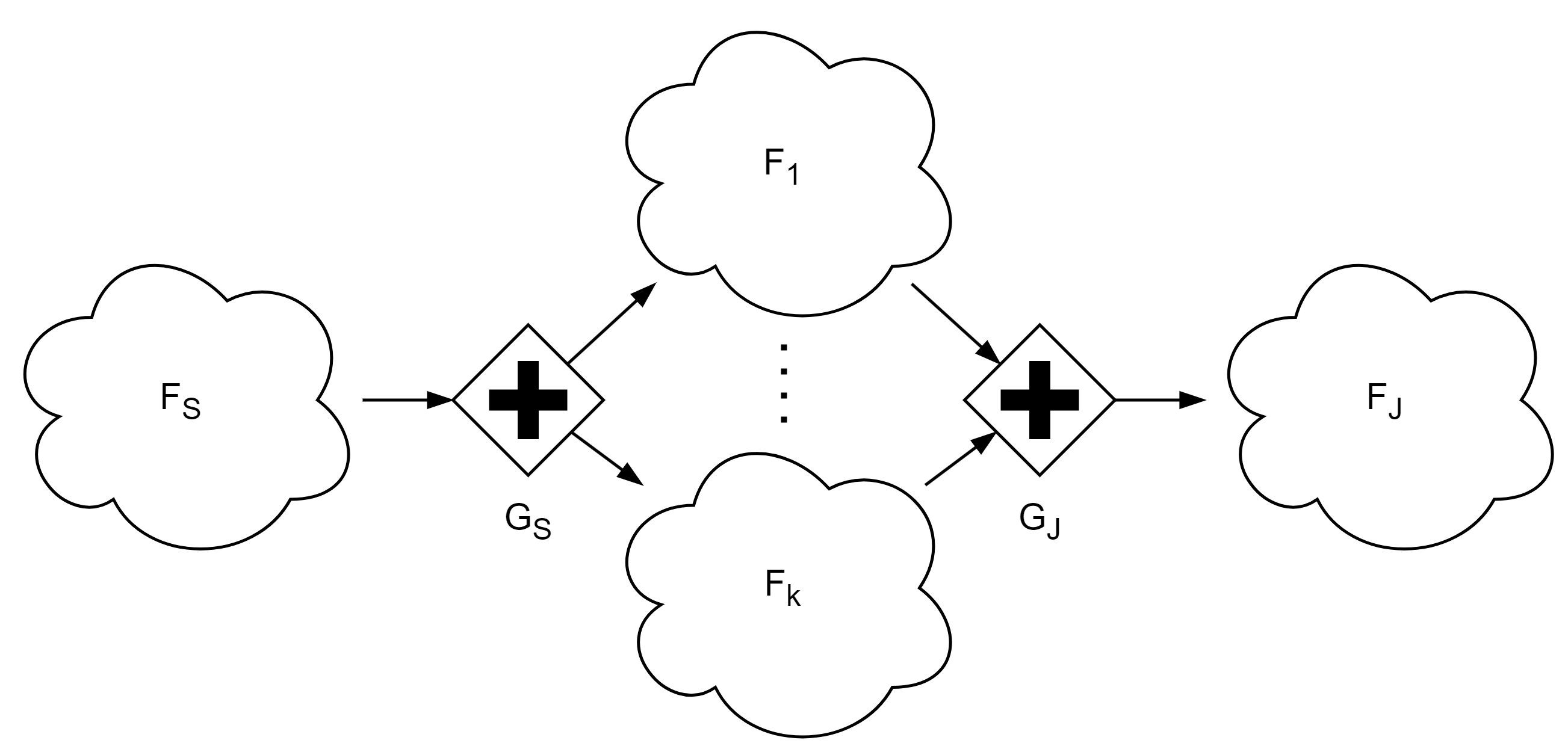
Due to their behaviour, parallel and inclusive gateways are treated differently. Namely, Figure 13 shows a generic BPMN subprocess involving parallel gateways, and Figure 14 shows the corresponding translation.
The translation of the parallel splitting gateway consists in calling the fork BeL function, which takes as arguments the method names corresponding to the tasks starting each of the parallel branches to be executed (). As a result of a call to fork, the current thread (i.e., the one leading to ) is terminated, and new threads are started, each corresponding to .
On the other end of the parallel, the parallel joining gateway uses the join BeL function to execute (on a new thread) the next task () once all the parallel branches reached it.
BeL implements fork and join in two ways. One relies on standard Java multithreading (true parallel). The other one approximates the parallel by running the parallel branches sequentially. This is useful to easier check errors in the process definition, since it generates sequential traces that are easier to debug, but may lead to deadlocks if synchronization is required (e.g., messages are exchanged between parallel branches). The user may enable sequential execution when needed, whilst true parallel execution is the default.
Finally, inclusive gateways are similar to parallel gateways, but only edges having a true condition are selected for parallel execution.
4.4 DMN Model Translation
In this section, we describe the behaviour of function translateDMN that is called in line 3 of Algorithm 1. We recall that each DMN table contained in the input tables set has the form shown in Figure 8.
Given this, each decision table is translated into a set of three classes, as shown in Figure 15: a class encapsulating the table inputs (decision variables, dmn_dtable_GenTabDT_arguments), another for the outputs (derived values, dmn_dtable_GenTabDT_result) and a main class containing the decision logic, dmn_dtable_GenTabDT, with a static execute method that is used to execute the decision process. This is performed by nested ifs, where each condition represent the Java version of the corresponding FEEL condition , obtained via FEEL2Java .
It is worth noting that the default case of a decision table, if present, such as row in Figure 8, becomes the final else statement in the decision code of Figure 15. Otherwise, the translator automatically adds a last else statement calling an internal method that ends the decision process with a failure if no other condition matches the given arguments.
4.5 Translation of Business Rule Tasks
As already recalled, the bridge between a BPMN process and its linked DMN tables is provided by business rule tasks, where DMN decision tables are invoked in order to assign values to some process variables. Such values must be determined by “executing” the DMN table, which may depend also on other variables. The assigned variables may then be used, e.g., in a gateway to redirect the execution flow.

Figure 16 shows a generic BPMN containing a business rule task. Such task is configured to invoke the GenTabDT shown in Figure 8, passing the result of the FEEL expressions as the table inputs , respectively, and assigning the result values to the process variables , respectively.
This diagram leads to the generation of the code shown in Figure 17, which first packages the table parameters in the table arguments class (using FEEL2Java to translate the input expressions to the Java counterpart ), then calls the decision table execute method, and finally unpacks the decision result assigning it to the output process variables .
4.6 Translation of Send and Receive Tasks

BDTrans also supports sending and receiving messages through send and receive tasks, which are typically used when two or more BPMN branches are executing in parallel.
Figure 18 shows a generic Send task A and Receive task B. Both tasks are configured (in the BPMN editor) to use channel to exchange a message of type , containing parts . As a result, A creates an instance of with , where are FEEL expressions, whereas B uses the values from the received instance of to assign the process variables , as described by the Camunda extension elements calledDecision and ioMapping in the XML serialization of the task.
To implement the message exchange, the BeL framework creates a concurrent blocking queue for channel and a class Message_M that declares as member variables, as shown in the generated code in Figure 19.
The Send task A builds an instance of Message_M, assigns the expressions (resulting from applying FEEL2Java on ) to its members , and finally uses the sendMessage BeL function to send it on channel . On the other hand, the Receive task B uses the receiveMessage BeL function to retrieve (possibly blocking if the queue is empty) a message from channel and then assigns the values from its parts to the process variables , respectively.
4.7 An Example of BPMN Translation
To illustrate the code generation technique applied to concrete BPMN+DMN artefacts, we use the Shipment as a running example (see Section 3.2 and Figure 2).
The generated running example class contains the process and input variable definitions shown in Figure 20. The input variables are also listed in the generated inputs file shown in Figure 21.
Figure 22 shows an example of decision table translation, corresponding to the ChooseConsentDT decision table illustrated in Figure 7.
The BPMN start Event StartEvent_1 is encoded in method
EVENT_StartEvent_1_package_received shown in Figure 23. Note that the reported code has been simplified by omitting the internal calls to utility methods that generate and display the execution trace, as we will see in Section 4.8.1.
Gateways such as the splitting exclusive after the choose consent task and the joining exclusive before the end event in Figure 2 are rendered as shown in Figures 24 and 25, respectively, following the already discussed rationale.
Figure 22 shows the code generated by the Business Rule task choose consent.
Finally, Figure 27 shows the two end events of the running example: In particular, when an exception end event is activated, the code passes the event description and code (if available) to the error BeL function, as for the EVENT_Event_19ylwnc_no_shipment in Figure 27, in order to signal the specific exception occurred in the execution trace.
4.8 Main Implementation Details
In this section, we provide some implementation details which are relevant for the translation part discussed here. BDTrans takes as input BPMN 2.0 diagrams and DMN decision models serialized in their standard XML format [36, 37], possibly with some extensionElements introduced by the Camunda Modeler [14], mainly used to map inputs and output variables in various elements. For sake of simplicity and without loss of generality, we suppose that each BPMN file defines a single business process (though BDTrans is able to handle also multiple processes in a single file), whereas the decision tables referenced by such process can be described in one or more DMN files.
The generated output consists of Java classes and support files (used to implement BeL) that can be used for documentation, simulation, and verification purposes (the latter part is actually performed by the BDTest algorithm, see Figure 1 and Section 5), as well as a skeleton for ad-hoc process development.
If a valid Java compiler is found in the system, BDTrans also compiles the generated Java artifacts (which may produce a large number of classes) and packages them in an auto-executable JAR file. For simplicity, the compiled classes are placed in the root package, while the JAR contains two src and doc folders where the algorithm places the code sources and the other generated artifacts, respectively.
4.8.1 Process Graph and Execution Trace
The Java program generated by BDTrans , if executed, outputs a detailed execution description such as the one reported in Figure 28. The output reports the values assigned to the input variables and lists all the BPMN nodes encountered in execution order. When a business rule task is activated, the output also shows the decision table name and its results. Finally, when an end event is reached, the output reports the end status (success in this case).
However, while this output is designed to be human-readable, the model execution also generates an execution summary file useful to be automatically parsed. Figure 29 shows such file after an example run of the Shipment process. The file reports both the inputs used and the its output in terms of message, code and success status.
To this aim, the BeL framework can be configured to generate trace files that are actually a simplified version of the execution output shown in Figure 28 and report the nodes and edges of the process graph activated in execution order. The trace format is the same as the graph file, to simplify comparison. An example is shown in Figure 30.
4.9 Current Limitations
In this section we describe some current limitations of BDTrans, which we plan to overcome as future work (see Section 7). We point out that, even with such limitations, our approach is effective as shown by our experimental results (see Section 6).
A first limitation is given by BPMN processes in which a generic user task sets an input variable within a BPMN loop (e.g., suppose that the “measure weight” task in Figure 2 goes back to the “get length” task). In fact, the current version of BDTrans will reuse the same value in each iteration, even if it may potentially change. Solving such issue will entail detecting user tasks with such a behaviour, and handling them in a suitable way (i.e., many inputs value have to be provided for the same variable).
A second limitation impacts on the performance of the generated Java program. Namely, the current execution model involves nested method calls for each transition, so limiting the overall length of the execution traces to the size of the language call stack. While BPMNs are typically small-sized, this can become a performance issue for the execution of BPMN involving loops to be traversed multiple times. In order to overcome such limitation, a different translation scheme may be used when process execution efficiency is important (e.g., by employing a main execution loop which may handle a generic BPMN transition).
As a third limitation, BDTrans currently supports parallelism only in the setting shown in Figure 13. Instead, BPMN also allows usage of event-based gateways to decide when to branch threads basing on other threads actions (send/receive messages, signals and so on). Furthermore, we only support synchronization via message exchange, while BPMN also allows other ways of communication (e.g., signals). In order to overcome such limitation, we need to address the full BPMN support to parallelism.
A fourth limitation regards the BPMN elements which we do not consider in this paper, i.e., event-based gateways and inclusive/parallel gateways. In event-based gateways, edge conditions are not a FEEL Boolean expressions, but are based on events occurring outside the BPMN process. This is not a severe limitation, as event-based gateways may be modeled by introducing a new task setting a new input variable , and then replacing the event-based gateway with an exclusive one, whose edges have conditions on . As for inclusive/parallel gateways, BDTransTest already supports them (see Section 4.3.2), but we leave an evaluation of BPMN+DMN processes including parallel parts as future work (see Section 7). This also holds for tasks including send and receive operations, which are typically used when dealing to parallel BPMNs. Moreover, BDTrans disregards BPMN pools and lanes, if present. In fact, such BPMN elements are meant as annotations to recall who is executing a set of tasks, thus it is not important in the verification problem, our focus here.
However, even with the aforementioned limitations due to its current development phase, BDTrans is already capable to translate realistic and complex BPMN and DMN artefacts, as shown by the examples reported in this paper.
4.10 BDTrans Correctness
To conclude this section, we discuss the correctness for our translation procedure BDTrans (Algorithm 1), assuming the input BPMN does not use parallel nor inclusive gateways.
By borrowing ideas both from model checking [8] and the notion of bisimulation [42], let be the state space of the input BPMN+DMN , where is the set of nodes (tasks, events and gateways) of and the set of all values for each variable of , including the special undefined value . Thus, if are the variables of with domains , then . We also define a function to extract the BPMN state from a transition system state, and a function to extract the variables values part. As an example, for the BPMN in Figure 2, a possible state is , and get length. This allows us to the define the transition relation of as , such that iff i) there is an edge in , ii) satisfies the condition on , if any, and iii) is obtained by modifying accordingly to actions to be taken on (possibly depending on tables in ). In the same example above, if we name the gateway between the “get length” and “measure weight” tasks as , we have that , being and . This also defines paths of as sequences of states such that for all , being a start event of . Note that, in our definition, a path may not terminate in an end event.
On the other hand, we define the trace of the Java class as the output of . More formally, such a trace consists of a sequence , where are nodes of and contains one value (possibly ) for all variables of .
Theorem 4.1 states the correctness of our translation; its proof follows from how the translation itself is carried out.
Theorem 4.1
Let be a BPMN and a set of DMN tables linked to it, respectively, with variables . Suppose fulfills the limitations of Section 4.9 and does not use neither parallel nor inclusive gateways, and let be the result of BDTrans in Algorithm 1 when applied to . Then, for each path of , there exists one unique trace of s.t. and for all . The viceversa also holds.
5 BPMN+DMN Testing and Coverage Analysis
In this section, we describe the second part of our BDTransTest tool, i.e., the algorithm which takes as input a set of Java classes describing a given BPMN+DMN , a description of the domains for the input variables, and performs thorough testing of , also measuring the achieved coverage. From now on, we will refer to such algorithm as BDTest, as depicted in Figure 1.
The rest of this section is organized as follows. Section 5.1 describes the second input of BDTest, i.e., the information on the domains of the input variables. Section 5.2 describes how the verification is performed.
5.1 BPMN Inputs Analysis
As already anticipated in Section 4.2 and Figure 1, BDTest also needs a description of the input variables used in , together with all possible information on their domains. This is accomplished by function getVarsDoms, called in line 2 of Algorithm 1, which returns a set of triplets , where is a variable, its Java type and contains the information that is actually needed at this stage. Namely, may be of 4 different types:
-
1.
ENUM, being a finite set of constant values, which means that variable is an enumerative variable which may only take values in . This is caused by being only used in direct equality comparisons within the input BPMN.
-
2.
BALL, being a numeric value, which means that variable takes values in a ball centered in . This is caused by being used in gateways with FEEL expression <= and its corresponding “default” case.
-
3.
RANGE, being a numeric range (both ends may be either included or excluded), which means that variable takes values in the range . This is caused by being used in gateways with FEEL expression in or in DMN employing .
-
4.
UNHANDLED, being a FEEL expression, which means that cannot be automatically understood by getVarsDoms, i.e., if does not fall into one of the above cases. BDTest allows the developer to provide the correct domain for such variables.
,
,
,
The information in set output by getVarsDoms is then written to an external inputs file. For each variable, such file also contains a random value, compatible with the determined domain. This file will be read by the model code during the initialization phase, in order to assign a value to all its input variables.
As an example, Figure 31 shows some FEEL expressions involving input variables and the corresponding generated inputs file.
5.2 Overall BPMN Testing
Our post-process algorithm BDTest takes as inputs the JAR file , the input variables file and the underlying graph file which are output by BDTrans. As a result, BDTest outputs FAIL or PASS, together with the achieved coverage percentages on blocks and on edges.
To this aim, BDTest is based on a subroutine RunOnce. Namely, RunOnce parses the input variables file , and assigns to each input variable in a random value taken from the corresponding domain (that can be again found in ). Then, it uses such randomly-generated values to execute . Since such an execution may turn out to be non-terminating (e.g., because of a loop in ), a configurable timeout is set for the execution itself. Finally, once RunOnce is terminated, BDTest uses its outputs and the graph file to keep track of which nodes and which edges have been traversed at least once. This is used to provide the final nodes coverage and branch coverage w.r.t. .
BDTest has several invocation modes, which are turned on by run-time options. In the following, we describe the most important ones.
-
1.
Repeatedly invoke RunOnce for times, for a given , stopping before executions are made (i.e., with ) if for given thresholds . This allows users to avoid “useless” executions once a given desired coverage has been reached. BDTest also implements the following variants of such modality, in order to provide more flexibility to users: i) only is checked; ii) only is checked; iii) is checked. The final result is PASS iff the selected condition on coverages is fulfilled at the end of the RunOnce invocations, and FAIL otherwise. Note that, as usual in testing, if the output is PASS then there exists executions yielding the desired coverage, but the viceversa does not hold. The dual property also holds: if there does not exist executions of achieving the desired coverage, then BDTest outputs FAIL, but the viceversa is not true.
-
2.
Repeatedly invoke RunOnce for times, for a given , stopping before executions are made (i.e., with ) if reports that a BPMN error block is traversed. In this case, as it is usual in testing, if the output is FAIL then there exists an execution of which traverses an error block of , but the viceversa does not hold. The dual property also holds: if there does not exist an execution of which traverses an error block of , then BDTest outputs PASS, but the viceversa is not true.
-
3.
Use a statistical model checking algorithm to decide the number of RunOnce invocations . In this case, two real numbers must be provided. BDTest allows the user to choose between two different properties to be verified: i) a BPMN error block is never traversed and ii) it is not possible to achieve overall coverage for given thresholds (the same 3 variants for the coverage check described above may be used as well). As a result, the probability that the final output is PASS when it should be FAIL is at most with confidence . Note that only type-I error are possible, i.e., if the final output is FAIL then it is always correct, while an output PASS may be wrong.
6 Experimental Evaluation
In order to evaluate the effectiveness of our methodology, we run our BDTransTest tool on two case studies. The first case study is the Shipment BPMN process described in Section 3.2; the second case study is the Surgery BPMN+DMN process from [4], which describes the decisions to be taken when operating a patient (see Figures 32 and 33).


For both such case studies, the experimental evaluation is organized so as to: i) generate the Java code from the input BPMN+DMN files; ii) run 1000 test cases, using a random numbers generator for the inputs (i.e., we run 1000 times the RunOnce subroutine discussed in Section 5). All our experiments are run on an Intel i9 with 2.5GhZ and 64GB of RAM.
Table 1 summarizes our results. The first column of Table 1 shows the resource measurement we consider, i.e.: the time and RAM required for the completion of Java code generation and test cases execution, the time and RAM for Java code generation from BPMN and DMN files only, the average and standard deviation for test cases execution time, the maximum RAM required by all test case executions, and finally the coverage achieved in terms of nodes and edges percentage. The other two columns of Table 1 show the corresponding values for the given case study, i.e., Surgery for the second column and Shipment for the third column.
As a result, times (and RAM) requirements for Java code generation and test cases setting and execution are negligible, while allowing to complete a verification phase with at least 70% coverage in a matter of a few minutes. This shows the feasibility of our approach.
| Measure | Surgery | Shipment |
|---|---|---|
| Total time (mm:ss) | 2:44 | 2:41 |
| Total RAM (MB) | 28.4 | 28.4 |
| Java generation time (secs) | 1.32 | 1.03 |
| Java generation RAM (MB) | 189 | 172 |
| Avg test exec time (secs) | 0.1 | 0.1 |
| Stddev test exec time (secs) | 0.006 | 0.006 |
| Max test exec RAM (MB) | 57.3 | 56.9 |
| Nodes coverage | 87.5% | 75.0% |
| Edges coverage | 81.5% | 70.6% |
7 Conclusions and Future Work
In this paper we introduced BDTransTest, a novel methodology and tool to perform execution and verification of business processes described using BPMN and also encompassing DMN tables. Namely, BDTransTest first translates the input BPMN+DMN files in an executable Java class, then exploits the generated Java class to perform testing of the given .
We remark that the translation part is valuable also if taken alone, as it allows both static inspection and framework-free execution of . On the contrary, current BPMN frameworks like, e.g., Camunda, does not provide details on the code being used to simulate a process, and the simulation itself requires the full framework to be active and running.
As for the verification part, it allows to detect process input variables and guess relevant input values for such variables. Our experimental results shows that, on our case studies, 1000 test cases are enough to obtain more than 70% coverage in terms of both nodes and edges in the original BPMN process. This shows the effectiveness of our approach.
Finally, we outline our main lines of future work on BDTransTest: i) overcome all limitations discussed in Section 4.9; ii) enrich the BPMN verification part by measuring glass-box control-flow-graph-based testing coverages like loop boundary [47] and definition-use pairs adequacy criteria [41]; iii) enrich the DMN verification part by measuring Modified Condition/Decision Criterion (MC/DC) coverage [25].
References
- [1] (2019) A sysml-based approach to requirements traceability using bpmn and dmn. In ICSEA 2019, The Fourteenth International Conference on Software Engineering Advances, pp. 210–216. External Links: ISBN 978-1-61208-752-8 Cited by: §2.
- [2] (2016) Verification of bpmn 2.0 process models: an event log-based approach. Procedia Computer Science 100, pp. 1064–1070. External Links: ISSN 1877-0509, Document Cited by: §2.
- [3] (2013) Abstract Logical Model Checking of Infinite-State Systems Using Narrowing. In 24th International Conference on Rewriting Techniques and Applications (RTA 2013), F. van Raamsdonk (Ed.), Leibniz International Proceedings in Informatics (LIPIcs), Vol. 21, Dagstuhl, Germany, pp. 81–96. Note: Keywords: model checking, infinite states, rewrite theories, narrowing External Links: ISBN 978-3-939897-53-8, ISSN 1868-8969, Link, Document Cited by: §2.
- [4] (2021) Putting bpmn and dmn to work: a pediatric surgery case study. In 2021 IEEE International Conference on Digital Health (ICDH), Vol. , pp. 154–159. External Links: Document Cited by: Figure 32, Figure 33, §6.
- [5] (2020) Test case generation from bpmn with dmn. In Proceedings of the 2019 3rd International Conference on Software and E-Business, ICSEB ’19, New York, NY, USA, pp. 92–96. External Links: ISBN 9781450376495, Document Cited by: §2.
- [6] (2020) Verification of bpmn models. In Complex Systems Design & Management, G. A. Boy, A. Guegan, D. Krob, and V. Vion (Eds.), Cham, pp. 27–36. External Links: ISBN 978-3-030-34843-4 Cited by: §2.
- [7] (2020) Automatic verification of bpmn models. In 10th European Congress on Embedded Real Time Software and Systems (ERTS 2020), Cited by: §2.
- [8] (2018) Handbook of model checking. 1st edition, Springer Publishing Company, Incorporated. External Links: ISBN 3319105744 Cited by: §4.10.
- [9] (2023-06) A study on the usage of the bpmn notation for designing process collaboration, choreography, and conversation models. Business & Information Systems Engineering 66, pp. 1–24. External Links: Document Cited by: §1.
- [10] (2024) Empirical evidence of dmn errors in the wild - an sap signavio case study. In Business Process Management Workshops, J. De Weerdt and L. Pufahl (Eds.), Cham, pp. 326–336. External Links: ISBN 978-3-031-50974-2 Cited by: §2.
- [11] (2021) A formal approach for the analysis of bpmn collaboration models. Journal of Systems and Software 180. External Links: Document Cited by: §2.
- [12] (2022) Formalising and animating multiple instances in bpmn collaborations. Information Systems 103, pp. 101459. External Links: ISSN 0306-4379, Document, Link Cited by: §2.
- [13] (2016) An explorative analysis of the notational characteristics of the decision model and notation (dmn). In 2016 IEEE 20th International Enterprise Distributed Object Computing Workshop (EDOCW), Vol. , pp. 1–9. External Links: Document Cited by: §1.
- [14] (2023) Exploring the impact of workflow engines on business process management in enterprise applications. a case-study: camunda. In 2023 17th International Conference on Engineering of Modern Electric Systems (EMES), Vol. , pp. 1–4. External Links: Document Cited by: §4.8.
- [15] (2021) Integrating bpmn and dmn: modeling and analysis. Journal on Data Semantics 10 (1), pp. 165–188. External Links: Document Cited by: §2, Figure 2, Figure 5, Figure 6, Figure 7, §3.2, §3.3.
- [16] (2019) Hierarchical verification for the bpmn design model using state space analysis. IEEE Access 7 (), pp. 16795–16815. External Links: Document Cited by: §2.
- [17] (2012) Automatic execution of business process models: exploiting the benefits of model-driven engineering approaches. Journal of Systems and Software 85 (3), pp. 607–625. Note: Novel approaches in the design and implementation of systems/software architecture External Links: ISSN 0164-1212, Document, Link Cited by: §2.
- [18] (2012) Direct verification of bpmn processes through an optimized unfolding technique. In 2012 12th International Conference on Quality Software, Vol. , pp. 179–188. External Links: Document Cited by: §2.
- [19] (2013) CADP 2011: a toolbox for the construction and analysis of distributed processes. Int. J. Softw. Tools Technol. Transf. 15 (2), pp. 89–107. External Links: Link, Document Cited by: §2.
- [20] (2018) BPMN 2.0: the state of support and implementation. Future Generation Computer Systems 80, pp. 250–262. External Links: ISSN 0167-739X, Document, Link Cited by: §2.
- [21] (2021) DMN 1.0 verification capabilities: an analysis of current tool support. In Business Process Management Forum, A. Polyvyanyy, M. T. Wynn, A. Van Looy, and M. Reichert (Eds.), Cham, pp. 37–53. External Links: ISBN 978-3-030-85440-9 Cited by: §2.
- [22] (2009) The process: business process modeling using bpmn. Meghan-Kiffer Press. External Links: ISBN 9780929652269, LCCN 2009923535 Cited by: §1.
- [23] (2020) Comparing bpmn to bpmn + dmn for iot process modelling: a case-based inquiry. In Proceedings of the 35th Annual ACM Symposium on Applied Computing, SAC ’20, New York, NY, USA, pp. 53–60. External Links: ISBN 9781450368667, Document Cited by: §1.
- [24] (2021) Code compliance checking of railway designs by integrating bim, bpmn and dmn. Automation in Construction 121, pp. 103427. External Links: ISSN 0926-5805, Document Cited by: §1.
- [25] (2001) A practical tutorial on modified condition/decision coverage. DIANE Publishing. External Links: ISBN 9781428995994, Link Cited by: §7.
- [26] (2022) A first-order logic verification framework for communication-parametric and time-aware bpmn collaborations. Information Systems 104, pp. 101765. External Links: ISSN 0306-4379, Document Cited by: §2.
- [27] (2023) Process-oriented requirements definition and analysis of software components in critical systems. Computers 12 (9). External Links: ISSN 2073-431X, Document Cited by: §2.
- [28] (2021) A lightweight bpmn extension for business process-oriented requirements engineering. Computers 10 (12), pp. 171. Cited by: §2.
- [29] (2022) Modeling, executing and monitoring iot-driven business rules with bpmn and dmn: current support and challenges. In Enterprise Design, Operations, and Computing, J. P. A. Almeida, D. Karastoyanova, G. Guizzardi, M. Montali, F. M. Maggi, and C. M. Fonseca (Eds.), Cham, pp. 111–127. External Links: ISBN 978-3-031-17604-3 Cited by: §2.
- [30] (2014) Verification and validation approach of bpmn represented construction processes. In Creative Construction Conference, Cited by: §2.
- [31] (2024) BPMN analyzer 2.0: instantaneous, comprehensible, and fixable control flow analysis for realistic BPMN models. In Proceedings of the Best Dissertation Award, Doctoral Consortium, and Demonstration & Resources Forum at BPM 2024 co-located with 22nd International Conference on Business Process Management (BPM 2024), Krakow, Poland, September 1st to 6th, 2024, A. del-Río-Ortega, M. Montali, S. Rinderle-Ma, H. A. Reijers, J. vom Brocke, M. Weske, B. Depaire, M. Indulska, H. van der Aa, W. T. Adrian, L. Genga, S. J. J. Leemans, K. Gdowska, M. T. Gómez-López, J. Rehse, and S. Agostinelli (Eds.), CEUR Workshop Proceedings, Vol. 3758, pp. 66–70. Cited by: §2.
- [32] (2017) VBPMN: automated verification of bpmn processes. In 13th International Conference on integrated Formal Methods (iFM 2017), Cited by: §2.
- [33] (2023) Assessing business process models: a literature review on techniques for bpmn testing and formal verification. Business Process Management Journal 29 (8), pp. 133–162. External Links: Document Cited by: §2.
- [34] (2016) Verification of bpmn model functional completeness by using the topological functioning model. In 11th International Conference on Evaluation of Novel Software Approaches to Software Engineering (ENASE 2016), pp. 349–358. External Links: ISBN 978-989-758-189-2 Cited by: §2.
- [35] (2025) Runtime defect prediction of industrial business processes: a focused look at real-life sap systems. Journal of Systems and Software 222, pp. 112306. External Links: ISSN 0164-1212, Document, Link Cited by: §2.
- [36] (2011) Business Process Model and Notation (BPMN) Version 2.0. External Links: Link Cited by: §1, §4.8.
- [37] (2019) Decision Model and Notation Version 1.3. External Links: Link Cited by: §1, §4.8.
- [38] (2019) Friendly Enough Expression Language. External Links: Link Cited by: §3.1.
- [39] (2012) Making sense of business process descriptions: an experimental comparison of graphical and textual notations. Journal of Systems and Software 85 (3), pp. 596–606. Note: Novel approaches in the design and implementation of systems/software architecture External Links: ISSN 0164-1212, Document, Link Cited by: §1.
- [40] (2019) Business process model refactoring applying ibuprofen. an industrial evaluation. Journal of Systems and Software 147, pp. 86–103. External Links: ISSN 0164-1212, Document, Link Cited by: §2.
- [41] (1985) Selecting software test data using data flow information. IEEE Transactions on Software Engineering SE-11 (4), pp. 367–375. External Links: Document Cited by: §7.
- [42] (2011) Introduction to bisimulation and coinduction. Cambridge University Press. Cited by: §4.10.
- [43] (2015) A tool for the automatic verification of bpmn choreographies. In 2015 IEEE International Conference on Services Computing, Vol. , pp. 728–735. External Links: Document Cited by: §2.
- [44] (2008) Formal semantics and verification of bpmn transaction and compensation. In 2008 IEEE Asia-Pacific Services Computing Conference, Vol. , pp. 284–290. External Links: Document Cited by: §2.
- [45] (2022) Modelling and executing iot-enhanced business processes through bpmn and microservices. Journal of Systems and Software 184, pp. 111139. External Links: ISSN 0164-1212, Document, Link Cited by: §2.
- [46] (2022) MultiVeStA: statistical analysis of economic agent-based models by statistical model checking. In From Data to Models and Back, J. Bowles, G. Broccia, and R. Pellungrini (Eds.), Cham, pp. 3–6. External Links: ISBN 978-3-031-16011-0 Cited by: §2.
- [47] (2013-08) Fast loop boundary coverage testing in symbolic execution. In Advanced Measurement and Test III, Advanced Materials Research, Vol. 718, pp. 2314–2317. External Links: Document Cited by: §7.