[a]Davide Depaoli
Status of the SST Camera for the Cherenkov Telescope Array
Abstract
The Cherenkov Telescope Array will be the next generation ground-based gamma ray observatory in the energy range from a few tens of GeV to hundreds of TeV. It will be built on two sites, one for each hemisphere, to cover the entire sky. The observatory will consist of telescopes of three different sizes: large, medium and small, with primary reflectors of 23, 11.5 and 4.3 m in diameter, respectively. The Small-Sized Telescopes (SSTs) will focus on the highest energies; at least 37 (and up to 70) will be deployed at the southern site in Paranal, Chile, covering several square kilometers. They will have a Schwarzschild-Couder dual-mirror design, with a primary reflector of about 4 meters in diameter. This configuration leads to a compact camera, with a diameter of about and a weight of less than . Its focal plane consists of 2048 Silicon Photomultiplier pixels, each one read independently by a state-of-the-art full waveform readout. The camera design is now in the final stage and the first components are being tested. In this contribution we discuss the design choices, and present test results from latest developments.
1 Introduction
The Small-Sized Telescopes (SSTs) of the Cherenkov Telescope Array (CTA) are a crucial component of the CTA-South site located in Paranal, Chile, where they will extend the sensitivity of the observatory to the highest energies, from about to at least . At least 37 (and up to 70) will be built there; because of their large number, their camera should be inexpensive, reliable, and easy to maintain. During the CTA development phase, different solutions were proposed for the SST camera [1, 2, 3, 4].
After an initial development and then a harmonization process, CTA selected the SST technology: the telescopes will have a Schwarzschild-Couder dual-mirror design, based on the ASTRI structure and on the Compact High Energy Camera in its Silicon Photomultiplier (SiPM) variant (CHEC-S) [5]. The SST camera is therefore the evolution of the CHEC-S prototype, and its design is being finalized by a team of 11 institutes from different countries, located in Germany, the United Kingdom, the Netherlands, Japan and Australia. The baseline plan is to deploy at least 37 SSTs at the CTA South site (Paranal, Chile).
2 Design Choices
The SSTs have a dual-mirror design based on the Schwarzschild-Couder principle, which allows for a small, light and compact camera with a diameter of about and a weight of less than . The camera will cover a field of view of about and will use SiPMs as the photosensors, which are robust to high illumination levels, provide high photon detection efficiency, and are extremely affordable for the size required for the SST.

Figure 1 shows the overview design of the SST camera. The camera is housed in an aluminum enclosure that measures ; the entire camera weighs approximately . The sensors in the focal plane are protected by a flat window, which has a special layered coating that restricts light outside the range, to minimize the interference from the night sky background (NSB) photons and maximize the detection of Cherenkov light. Two light-tight motorized aluminum doors protect the camera during the day.
The camera design is modular and divided into 32 identical modules. Each module has a tile of 64 SiPMs each, for a camera total of 2048 pixels. The tiles in the focal plane are arranged to follow the radius of curvature that arises from the telescope optics. The selected SiPMs are manufactured by Hamamatsu Photonics using the LVR3 technology, have an area of and do not have any protective coating (single pixel: S14520-2246, tile part number: S14521-1720). Tests performed in the collaboration showed a photon detection efficiency of about at the operating voltage, along with a crosstalk of about .
Each SiPM tile is thermally connected to an in-house machined liquid-cooled heat sink designed to remove the power dissipated by the sensors and electronics. The temperature is monitored by 4 temperature sensors per tile. The SiPMs are connected to the Focal Plane Electronics, which is a set of stacked printed circuit boards (PCBs) that provide SiPM bias and signal preamplification. Each SiPM is individually biased to compensate for different gains in the same tile; the voltage can be set by a Digital to Analogue Converter (DAC). The SiPM signals are preamplified by transimpedance amplifiers; a pole-zero cancellation circuit shapes the signals and removes the long signal tail to achieve a Full Width at Half Maximum (FWHM) of approximately . The signals are then sent to the the readout electronics, which consists of three interconnected boards per module. Based on the TeV Array Readout Electronics with GSa/s sampling and Event Trigger (TARGET) Application Specific Integrated Circuits (ASICs), it performs the first level trigger and the digitization of the signals [6]. All the modules are connected to a Backplane PCB.
The preamplified signals are sent to the TARGET module where they are reamplified and then split into two lines: a fast-signal, and a slow-signal line.
The fast signal is shaped again and then AC-coupled to the TARGET sampling ASICs (CTC) and the TARGET trigger ASICs (CT5TEA). Each of these ASICs receives 16 input channels, so each module requires four of them to handle the 64-pixel SiPM tile. The TARGET-CTC ASICs in the SST camera are configured to sample and digitize the fast signal at in a window (settable in blocks up to ). The samples are stored in a capacitor array and then digitized by 12bit Wilkinson ADCs. The first level trigger is performed by the TARGET-CT5TEA ASICs. A trigger signal is sent when the analogue sum of the fast signals from four adjacent SiPMs (a “superpixel”) exceeds a configurable threshold. Each trigger signal from 512 superpixels is sent to the Backplane board, for the determination of the camera-level trigger, configured to require a coincidence between two neighboring superpixels. An overview of the camera trigger is shown in Figure 2. Then the signal is sent to the FPGAs hosted in the TARGET modules, which in turn instruct the TARGET-CTCs to digitize the signals (64 per module). These waveforms are then sent to the Backplane, combined into a link and then transmitted off-camera via a fiber-optic cable.

In the slow signal line, the DC-coupled signal is integrated by a integrator and then digitized by a ADC; the data is then sent to the FPGAs. The resulting values are used to determine the brightness level for each pixel, which is ideal for measuring NSB levels and for tracking the telescope’s pointing using known star locations.
An array-wide White Rabbit system connected to a dedicated Timing Board provides absolute timestamps to each event.
The camera has a fast and variable intensity illumination system based on LED flashers to allow on-site calibration. The main flasher is located in the center of the secondary mirror and flashes the camera directly. Additional flashers are located in the corner of the camera (for indirect illumination by reflection from the secondary mirror) and connected to a scintillating fiber that runs around the inside of the focal plane, below the window (to provide low-light pulses when the door is closed, useful for calibrating the gain of the SiPMs).
The Slow Control Board (based on a general purpose microcontroller) controls the doors, manages and controls the power distribution, communicates with the LED flashers, communicates with the Backplane, and monitors the camera’s internal environment.
An external chiller cools the camera by circulating a cooled liquid through the focal plane plate. Fans inside the camera move the cold air around. The camera is hermetically sealed and humidity is maintained at an acceptable level by a breather desiccator.
3 Development Status and First Measurements
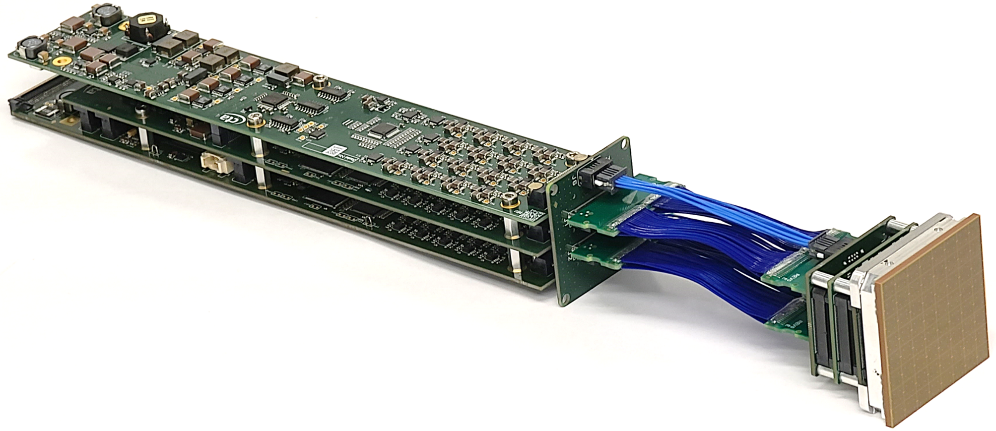
The design of the SST camera is nearly complete, with only minor adjustments and optimizations remaining. The first complete modules, consisting of TARGET modules, Focal Plane Electronics and SiPMs, have been assembled and are undergoing testing. The modules are kept in a light-tight box, and the SiPM tile is enclosed in a custom aluminum frame with a UV transparent window connected to a liquid chiller. A picture of the module under test in the University of Leicester laboratories is shown in Figure 3. A focused laser beam mounted on an x-y stage is used to fire one pixel at a time. During each run, data is stored for every pixel, both fired and unfired.
Figures 4a and 4b show the results of full width at half maximum and rise time measurements of the signals for each illuminated pixel of a single module. The response is uniform, with the average FWHM among the tiles being with a standard deviation of (), and the average rise time being with a standard deviation of (). These preliminary results are in accordance with the design specifications.
With this setup, by firing only one pixel with a focused light, it is possible to evaluate the crosstalk between pixels. The 2D map of the peak-to-peak and charge crosstalk measurements for the module under test is shown respectively in Figure 5a and 5b. The y-axis shows the fired pixels and the x-axis shows all pixels of the module. For each pixel, the crosstalk is measured as the ratio of the peak-to-peak (or charge) value in the pixel to that in the fired pixel; by definition, it is zero for the fired pixel. In this measure we have the combination of all possible crosstalk effects we can have in the module: crosstalk between SiPMs (light reflected from the window), between signal lines, between ASIC channels, and between connector pins. The charge crosstalk is always less than , and peak-to-peak crosstalk is always below . While the first one is important for understanding the quality of the Cherenkov images, the second one is critical for the trigger. In fact, a trigger signal occurs when the sum of four adjacent pixels (superpixel) exceeds a certain threshold; if there is crosstalk in an adjacent channel, it can negatively affect the trigger. This effect is currently under investigation.


The next batch of modules have been produced and are currently undergoing tests in the University of Leicester, UK, at Max Plank Institute for Nuclear Physics, Germany and at Erlangen Centre for Astroparticle Physics, Germany. Further tests will be critical to verify the initial results reported here.
Regarding the illumination system, a prototype flasher has been extensively tested, demonstrating its ability to produce fast and variable intensity light pulses. The design of the flasher is now being finalized. A first prototype of the Slow Control Board has been built and successfully tested and will soon be integrated into the door control system. A complete set of doors have been built and tested. The enclosure design is completed and a first version has been built and tested.
4 Conclusions and Future Prospects
The design of the SST camera is nearly complete and the first copies of subsystems are being tested. Initial results are positive and indicate that all design requirements will be met. At the end of 2023, the first quarter of the camera (QCAM) is planned to be built. It will consist of 8 camera modules (512 readout channels), the Slow Control Board, all the mechanics and a quarter Backplane. QCAM will then undergo detailed laboratory testing, after which a complete engineering camera (ECAM) will be built and commissioned on a prototype telescope structure.
Acknowledgments
This work was conducted in the context of the CTA SST Collaboration. We are grateful for financial support from organizations and agencies listed in https://www.cta-observatory.org/consortium_acknowledgments/.
References
- [1] M. Heller et al. The single mirror small sized telescope for CTA. In 6th International Symposium on High Energy Gamma-Ray Astronomy, volume 1792, page 080003, 2017.
- [2] G. Pareschi. The ASTRI program in the context of the CTA Observatory. In ICRC2019, volume 36, page 758, 2019.
- [3] J. Zorn et al. CHEC-A compact high energy camera for CTA. NIM-A, 936:229–230, 2019.
- [4] D. Dumas et al. SST-GATE telescope: an innovative dual-mirror prototype for the CTA. In Ground-based and Airborne Telescopes V, volume 9145, page 91452Y, 2014.
- [5] R. White et al. The Small-Sized Telescopes for the Southern Site of the Cherenkov Telescope Array. In 37th International Cosmic Ray Conference, page 728, March 2022.
- [6] S. Funk et al. TARGET: A digitizing and trigger ASIC for the Cherenkov telescope array. In 6th International Symposium on High Energy Gamma-Ray Astronomy, volume 1792 of American Institute of Physics Conference Series, page 080012, January 2017.
Full Authors List: CTA SST Project
Antonelli Angelo1, Arnesen Tora2, Aschersleben Jann2, Attinà Primo3, Balbo Matteo4, Bang Sunghyun5, Barcelo Miquel6, Baryshev Andrey2, Bellassai Giancarlo14, Berge David8, Bicknell Chris9, Bigongiari Ciro1, Bonnoli Giacomo3, Bouley Frederic10, Brown Anthony11, Bulgarelli Andrea12, Cappi Massimo12, Caraveo Patrizia13, Caschera Salvatore7, Chadwick Paula11, Conte Francesco6, Cotter Garret15, Cristofari Pierre10, Dal Pino Elisabete Maria de Gouveia16, De Frondat Fatima10, De Simone Nico8, Depaoli Davide6, Dournaux Jean-Laurent10, Duffy Connor15 Einecke Sabrina17, Fermino Carlos Eduardo16, Funk Stefan18, Gargano Carmelo19, Giavitto Gianluca8, Giuliani Andrea13, Greenshaw Tim20, Hinton Jim6, Iovenitti Simone3, La Palombara Nicola13, Lapington Jon9, Laporte Philippe10, Leach Steve9, Lessio Luigi21, Leto Giuseppe14, Lloyd Sheridan11, Lombardi Saverio1, Lucarelli Fabrizio1, Macchi Alberto3, Martinetti Eugenio14, Miccichè Antonio14, Millul Rachele3, Mineo Teresa19, Mitsunari Takahashi5, Nayak Amrit11, Nicotra Gaetano22, Okumura Akira5, Pareschi Giovanni3, Penno Marek8, Prokoph Heike8, Rebert Emma10, Righi Chiara3, Rodeghiero Gabriele12, Ross Duncan9, Rowell Gavin17, Rulten Cameron11, Russo Federico12, Sanchez Ricardo Zanmar14, Saturni Francesco1, Schaefer Johannes18, Schwab Benni18, Scuderi Salvatore13, Sironi Giorgia3, Sliusar Vitalii4, Sol Helene10, Spencer Samuel18, Stamerra Antonio1, Tagliaferri Gianpiero3, Tajima Hiro5, Tavecchio Fabrizio3, Tosti Gino3, Trois Alessio7, Vecchi Manuela2, Vercellone Stefano3, Vink Jacco23, Walter Roland4, Watson Jason8, White Richard6, Wohlleben Frederik6, Zampieri Luca21, Zech Andreas10, Zink Adrian18
- 1
INAF - Istituto di Astrofisica e Planetologia Spaziali (IAPS), Via del Fosso del Cavaliere 100, 00133 Roma, Italy
- 2
Kapteyn Astronomical Institute, University of Groningen, Landleven 12, 9747 AD, Groningen, The Netherlands
- 3
INAF - Osservatorio Astronomico di Brera, Via Brera 28, 20121 Milano, Italy
- 4
Department of Astronomy, University of Geneva, Chemin d’Ecogia 16, CH-1290 Versoix, Switzerland
- 5
Department of Physics, Nagoya University, Chikusa-ku, Nagoya, 464-8602, Japan
- 6
Max Planck Institute for Nuclear Physics, Saupfercheckweg 1, 69117 Heidelberg, Germany, Saupfercheckweg 1, 69117 Heidelberg, Germany
- 7
INAF - Osservatorio Astronomico di Cagliari, Via della Scienza 5, 09047 Selargius, Italy
- 8
Deutsches Elektronen-Synchrotron, Platanenallee 6, 15738 Zeuthen, Germany
- 9
School of Physics and Astronomy, University of Leicester, Leicester, LE1 7RH, United Kingdom
- 10
LUTH, GEPI and LERMA, Observatoire de Paris, Université PSL, Université Paris Cité, CNRS, 5 place Jules Janssen, 92190, Meudon, France
- 11
Centre for Advanced Instrumentation, Department of Physics, Durham University, South Road, Durham, DH1 3LE, United Kingdom
- 12
INAF - Osservatorio di Astrofisica e Scienza dello spazio di Bologna, Via Piero Gobetti 93/3, 40129 Bologna, Italy
- 13
INAF - Istituto di Astrofisica Spaziale e Fisica Cosmica di Milano, Via A. Corti 12, 20133 Milano, Italy
- 14
INAF - Osservatorio Astrofisico di Catania, Via S. Sofia, 78, 95123 Catania, Italy
- 15
University of Oxford, Department of Physics, Clarendon Laboratory, Parks Road, Oxford, OX1 3PU, United Kingdom
- 16
Escola de Artes, Ciências e Humanidades, Universidade de São Paulo, Rua Arlindo Bettio, CEP 03828-000, 1000 São Paulo, Brazil
- 17
School of Physics, Chemistry and Earth Sciences, University of Adelaide, Adelaide SA 5005, Australia
- 18
Friedrich-Alexander-Universität Erlangen-Nürnberg, Erlangen Centre for Astroparticle Physics, Nikolaus-Fiebiger-Str. 2, 91058 Erlangen, Germany
- 19
INAF - Osservatorio Astronomico di Palermo “G.S. Vaiana”, Piazza del Parlamento 1, 90134 Palermo, Italy
- 20
University of Liverpool, Oliver Lodge Laboratory, Liverpool L69 7ZE, United Kingdom
- 21
INAF - Osservatorio Astronomico di Padova, Vicolo dell’Osservatorio 5, 35122 Padova, Italy
- 22
INAF - Istituto di Radioastronomia, Via Gobetti 101, 40129 Bologna, Italy
- 23
Anton Pannekoek Institute/GRAPPA, University of Amsterdam, Science Park 904 1098 XH Amsterdam, The Netherlands