Addressing Data Misalignment in Image-LiDAR Fusion on Point Cloud Segmentation
Abstract
With the advent of advanced multi-sensor fusion models, there has been a notable enhancement in the performance of perception tasks within in terms of autonomous driving. Despite these advancements, the challenges persist, particularly in the fusion of data from cameras and LiDAR sensors. A critial concern is the accurate alignment of data from these disparate sensors. Our observations indicate that the projected positions of LiDAR points often misalign on the corresponding image. Furthermore, fusion models appear to struggle in accurately segmenting these misaligned points. In this paper, we would like to address this problem carefully, with a specific focus on the nuScenes dataset and the SOTA of fusion models 2DPASS, and providing the possible solutions or potential improvements.
1 Introduction
Utilizing a single modality model is a prevalent approach when addressing perceptual challenges in deep learning. However, for systems that demand high accuracy and robustness, such as autonomous driving, this approach may not suffice. Without a doubt, autonomous driving perception has emerged as one of the most scrutinized areas of research in recent times. Given the paramount importance of safety and reliability in this domain, the fusion of multi-sensor data has become a must.

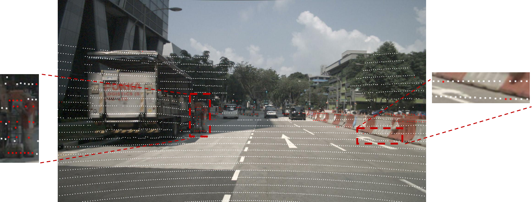
The task of fusing multiple modalities presents significant challenges, the priorof which is the alignment of data from disparate sensors. Coordinate transformation serves as a standard preprocessing step to align data between modalities, for example, transforming LiDAR points to align with the camera’s image plane. However, the synchronization between the LiDAR and camera is not precise, LiDAR points might projected onto wrong pixels. The existing researches on this topic have not addressed this issue adequately, even the best models in the open leaderboard. nuScenes caesar2020nuscenes is the most popular dataset for autonomous driving perception tasks, it provide multiple modalities data, including LiDAR, camera, radar, and GPS, and rich annotations, 3D bounding boxes, and point-level segmentation labels, etc. However, the projected positions of LiDAR points often misalign on the corresponding image since varying reasons, the example is shown in Figure 1, the official API of nuScenes also provide the same projection result. We also found that SemanticKITTIbehley2019semantickitti show the same problem, but it is not as serious as nuScenes.
yan20222dpass; zhuang2021perception are the top two opensourced models in the nuScenes LiDAR segmentation challenge in terms of multi-modality, 2DPASSyan20222dpass is one of the best model in the leaderboard, achieve 80.8 mIoU on the nuScenes test set, and 72.9 mIoU on SemanticKITTI test set. Nevertheless, all these three models do not address the misalignment problem in model design and dataset perspective, and we found that 2DPASS might fail to segment the misaligned points more often.
In the following sections, we will address how the LiDAR is projected onto the image, the reason why the misalignment problem occurs, and discuss the possible solutions or potential improvements.
2 Problem Definition
In this section, we will first show that how LiDAR points are projected onto the image, and then discuss the possible reasons why the misalignment problem occurs, finally, we will discuss the impact of the misalignment problem.
Coordinate Transformation and Rasterization
For a given LiDAR point cloud and a given image plane , where is the number of points in the point cloud scene, M is the number of pixels of the image. Assuming Point Cloud and RGB images are captured at the exactly same time, the objective is to rasterize the 3D points onto by using a series of matrices multiplying, the general camera calibration formula is given as:
| (1) |
where is the camera intrinsic matrix and is the camera extrinsic matrix, the transforms the world coordinates into camera coordinates, the K transforms the camera coordinates to pixel coordinates.
In SemanticKITTIbehley2019semantickitti dataset, and has been directly provided. Because of the difference between the frequency of capturing data of LiDAR and camera in NuScenes caesar2020nuscenes, we need to consider the timestamp of the extrinsic matrices, the is given as:
| (2) |
where the subscripts marks what the coordinates transform from and to, for instance, is the transformation matrix to project the view of the vehicle position at timestamp to its camera view, and so on.
The above process is widely addressed in the other related works yan20222dpass.
Why the Misalignment Problem Might Occur
The problem is also known as Sensors Time Synchronization Problem, the sensors are not synchronized in time. The misalignment problem might occur due to the following reasons:
- 1.
The different operating frequency of camera and LiDAR
- 2.
The trigger mechanism of camera, LiDAR, GPS and IMU
- 3.
The timestamp delay between camera, LiDAR, GPS and IMU
- 4.
The noise of intrinsic and extrinsic parameters
these factors tangled together and cause the misalignment problem, note that these are not the only reasons, but the most important ones, 9966179 address the other reasons in detail.
Let’s just take the first factor as an example, the LiDAR and camera are not synchronized in time, in nuScenes, for example, the LiDAR works at 20Hz, and the camera works at 12Hz, so the 12 camera exposures are speard evenly over the 20 LiDAR sweeps, assume the car is moving ar 40 km/h, the longest distance between two is 7.3 meters, this is not even considering other factors.
Unfortunately, these hardware limitations can not be solved in the near future, the possible way to reduce the impact of these limitations is via model design perspective.
The Impact of Misalignment Problem to Deep Learning Models
In zhuang2021perception, they use the approach we show in section 2.1 to project the LiDAR points onto a image plane, and concatenate with the corresponding RGB image, then feed the concatenated data into the RF fusion module. Which clearly would suffer from the misalignment problem.
The things are even clear in 2DPASS, each LiDAR point feature will concatenate with a corresponding pixel feature, unlike zhuang2021perception, even though the image is not used during inference stage, the knowledge distillation information is inevitably to be noisy by the misaligned pixel features.
In Figure 2, we show the inference results of 2DPASS in nuScenes, the red poins represent the wrong segmentation results. Compare with misaligned points in Figure 1, we can see that 2DPASS fails to segment on the misaligned points a lot, but in some cases, the building behind the truck is segmented correctly, this is because the points are actually far from the truck, the 3D features lead the segmentation results.
3 Possible Solutions and Potential Improvements
Utilizing the right image and LiDAR data is the key to solve the misalignment problem, unfortunately, it is not possible to know the specific root cause of every misaligned points. A feasible way is to design a model that is adaptive to the misalignment points, select the right pixel features by itself.
Architecture of 2DPASS Overview
As the architecture shown in Figure 3, for a given pair of 2D image and 3D point cloud, 2DPASS extracts 2D features and 3D features by 2D encoder FCNlong2015fully and 3D encoder SPVCNNtang2020searching, since they are both pyramid networks, the represents the feature extracted from l-th layer, the is the number of channels of features at l-th layer.
Because we would like to focus on the points in the image FOV, we first select the points in the image FOV to have in the 3D features , each could find a corresponding 2D feature by Coordinate Transformation and Ras- terization discussed in section 2.1.
are then input into a MLP layer, called 2D Learner, the purpose of 2D Learner is to narrow the gap between 2D and 3D features, after this, they are concatenated as fused features, written as:
| (3) |
The above process shows the details of the 2D and 3D fusion in 2DPASS, since might not be the right pixel features corresponding to because of misalignment, we would like to introduce a noval way to solve this problem.

Deformable Fusion
As the inspiration of xia2022vision, we consider Deformable Attation is a powerful tool to deal with the misalignment problem, it’s designed to select the position of key and value pairs in self-attention in a data-dependent way, where the offsets are predicted by a learnable offset network.
In 2DPASS scenarios, we would like to use the projected points as ther reference points, and find the offset of the corresponding pixel features with image features, the formula is given as:
| (4) |
where we follow the design of the offset network in xia2022vision, is the 2D image features and , and we could have the adaptive 2D features by:
| (5) |
where is the bilinear interpolation function, is the coordinates of the projected pixel positions, and the original misaligned is replaced by .
4 Future Work
In this paper, we address the misalignment problem in fusion task, and how the SOTA of fusion models 2DPASS is affected by this problem, also, we provide a possible solution to solve this problem. However, this idea is not fully verified by experiments yet, we will leave it and the analysis of the results to the future work.
References
- (1) H. Caesar, V. Bankiti, A. H. Lang, S. Vora, V. E. Liong, Q. Xu, A. Krishnan, Y. Pan, G. Baldan, and O. Beijbom, “nuscenes: A multimodal dataset for autonomous driving,” in Proceedings of the IEEE/CVF conference on computer vision and pattern recognition, pp. 11621–11631, 2020.
- (2) J. Behley, M. Garbade, A. Milioto, J. Quenzel, S. Behnke, C. Stachniss, and J. Gall, “Semantickitti: A dataset for semantic scene understanding of lidar sequences,” in Proceedings of the IEEE/CVF international conference on computer vision, pp. 9297–9307, 2019.
- (3) X. Yan, J. Gao, C. Zheng, C. Zheng, R. Zhang, S. Cui, and Z. Li, “2dpass: 2d priors assisted semantic segmentation on lidar point clouds,” in Computer Vision–ECCV 2022: 17th European Conference, Tel Aviv, Israel, October 23–27, 2022, Proceedings, Part XXVIII, pp. 677–695, Springer, 2022.
- (4) Z. Zhuang, R. Li, K. Jia, Q. Wang, Y. Li, and M. Tan, “Perception-aware multi-sensor fusion for 3d lidar semantic segmentation,” in Proceedings of the IEEE/CVF International Conference on Computer Vision, pp. 16280–16290, 2021.
- (5) E. R. Jellum, T. H. Bryne, T. A. Johansen, and M. Orlandić, “The syncline model - analyzing the impact of time synchronization in sensor fusion,” in 2022 IEEE Conference on Control Technology and Applications (CCTA), pp. 1446–1453, 2022.
- (6) J. Long, E. Shelhamer, and T. Darrell, “Fully convolutional networks for semantic segmentation,” in Proceedings of the IEEE conference on computer vision and pattern recognition, pp. 3431–3440, 2015.
- (7) H. Tang, Z. Liu, S. Zhao, Y. Lin, J. Lin, H. Wang, and S. Han, “Searching efficient 3d architectures with sparse point-voxel convolution,” in Computer Vision–ECCV 2020: 16th European Conference, Glasgow, UK, August 23–28, 2020, Proceedings, Part XXVIII, pp. 685–702, Springer, 2020.
- (8) Z. Xia, X. Pan, S. Song, L. E. Li, and G. Huang, “Vision transformer with deformable attention,” in Proceedings of the IEEE/CVF conference on computer vision and pattern recognition, pp. 4794–4803, 2022.