DESY-23-138
R&D for Positron Sources at High-Energy Lepton Colliders 11 1 Talk presented at the International Workshop on Future Linear Colliders (LCWS2023), 15-19 May 2023. C23-05-15.3.
Gudrid Moortgat-Picka,b, Sabine Riemannc, Peter Sieversd, Carmen Tenholtb
a University of Hamburg, Luruper Chaussee 149, 22761 Hamburg, Germany
b Deutsches Elektronen-Synchrotron DESY, Notkestr. 85, 22607 Hamburg, Germany
c Deutsches Elektronen-Synchrotron DESY, Platanenallee 6, 15738 Zeuthen, Germany
d CERN CH 1211 Geneva 23, Switzerland
Several designs for high-energy Lepton Colliders serving as Higgs factories but extendable to higher energies up to the TeV range are under discussion. The most mature design is the International Linear Collider (ILC), but also the Compact Linear Collider (CLIC) as well as the new concept of a Hybrid Asymmetric Linear Higgs Factory (HALHF) have a large physics potential. The first energy stage with GeV requires high luminosity and polarized beams and imposes an effort for all positron source designs at high-energy colliders. In the baseline design of the ILC, an undulator-based source is foreseen for the positron source in order to match the physics requirements. In this contribution an overview is given about the undulator-based source, the target tests, the rotating target wheel design, as well as the pulsed solenoid and the new technology development of plasma lenses as optic matching devices.
1 Motivation
A large amount of data has been collected from the Large Hadron Collider (LHC) and highly involved and precise analyses methods have been used, but no further discovery has been confirmed —although several excesses (e.g. consistent with a light scalar around 95 GeV) have been detected— and a possible window to new physics is still unknown. Nevertheless, there still exists a strong motivation for new physics (NP) beyond the Standard Model (SM), as, for instance, the quest for dark matter candidates, for explanation of the baryon-antibaryon asymmetry etc. Therefore further additional tools at future Lepton Colliders complementary to the High-Luminosity LHC (HL-LHC) analyses are required in order to identify promising windows to NP. The ILC [1, 2, 3] as well as the multi-TeV high-energy collider design CLIC [4] provide polarized beams at high intensity as well as at high energy. Challenging is the production of the high-intense positron beams. The ILC uses an undulator-based positron source in the baseline design [1, 2, 3] that produces a polarized positron beam already for the first stage [5], i.e. an initial energy of GeV [6], but is also applicable for higher centre-of-mass energies [7]. With simultaneously polarized beams and high luminosity[8], the physics potential of the ILC is optimized and well prepared for high precision physics as well as for new discoveries [9, 10]. There exists also the possibility to use an undulator-based positron source for CLIC [11]. The implementation of polarized beams at the HALHF concept [12] is currently under development. Alternative designs for generating polarized positrons via Laser-Compton backscattering have been proposed as well but are currently not pursued [13, 14].
It has already been shown that the physics precision requirements can not be fulfilled if only polarized electrons were available since in that case the systematic uncertainties get too large, see [15, 16, 17]. But also new physics searches might rely substantially on the availability of both beams polarized, see, for instance [18], where CP-violating Higgs couplings might be detectable already at GeV for transversely-polarized beams. Therefore the use of simultaneously-polarized beams is crucial for new physics searches at future lepton colliders.
1.1 Add-on’s when using simultaneously polarized and beams
Already at the first energy stage of the ILC with a centre-of-mass energy of GeV (ILC250) a polarized positron beam with would be available, upgradable to ( after implementation of the photon collimator) from GeV onwards, see [1, 19] for more technical details. The implementation of spin rotators and -flippers before the damping ring is required to switch helicities of both beams with similar frequency to exploit the increase in effective luminosity[20]. Furthermore, the spin rotators allow both the use of longitudinally- as well as transversely-polarized beams for physics interactions.
The availability of simultaneously polarized as well as beams leads to several advantages [8], since positron polarization plays the key role to obtain the following benefits and has a large impact on new physics contributions in Higgs, , and physics, starting already at the first energy stage of GeV!
- •
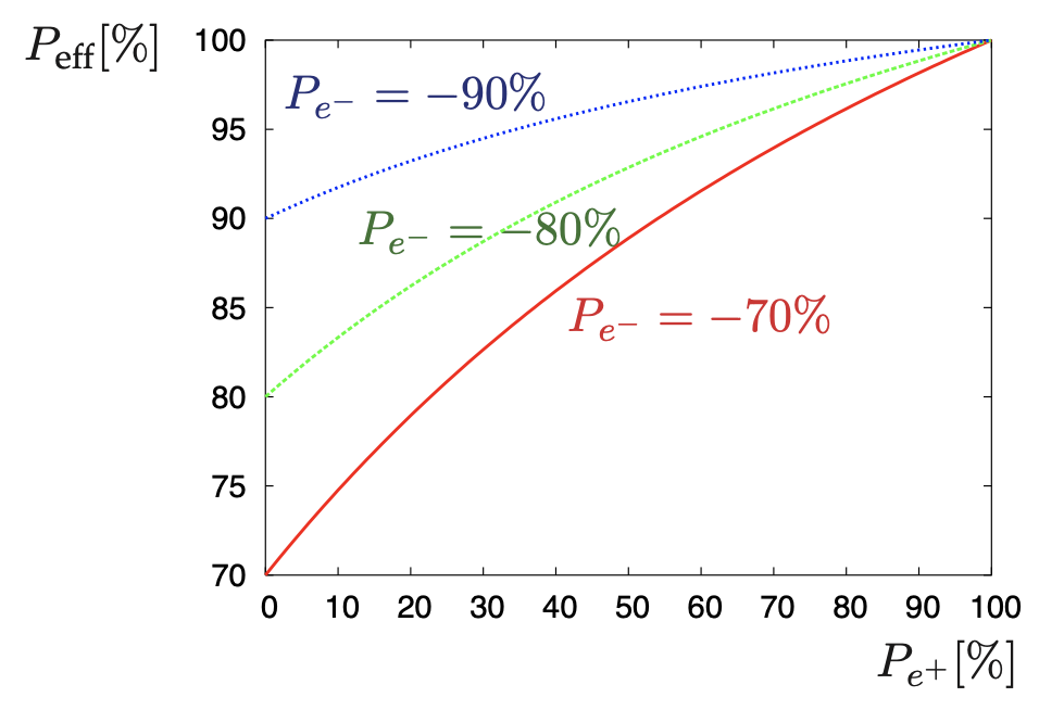
Better statistics: higher effective polarization , see Fig.1 (left panel), leads to higher rates and suppresses background processes; one expects at the ILC250 and at the upgraded ILC500 .
- •
Higher collision rates: higher effective luminosity leads to a higher fraction of actual collisions and offers therefore to achieve a specific number of event in less running time; one gets at the ILC250 an enhancement in the effective luminosity by a factor of and at the upgraded ILC500 by a factor of compared to the case with only polarized electron beams. The availability of both beams polarized reduces therefore the required running time by one third.
- •
Higher number of independent and new observables: four different data sets, opposite-site and like-sign polarization configurations can be evaluated and a larger set of polarization asymmetries can be exploited.
- •
But is not only required to improve significantly the statistics and saves running time but in particular also for getting systematic errors under control. Suitable observables are, for instance, left-right-asymmetries .
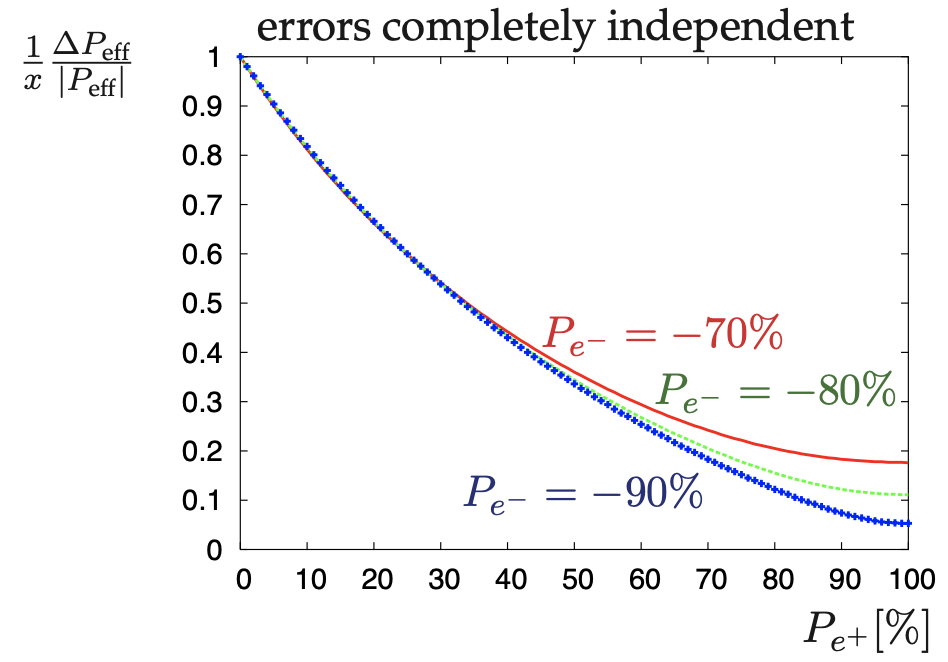
Applying polarized beams in general requires to measure the polarization of both beams as accurate as possible [8, 9]. Using Compton polarimeters up- and downstream an polarization uncertainty of is expected. A conservative lower bound for the resulting uncertainty in deriving , is shown in Fig.1 (right panel), where only the uncertainty in the polarization measurement has been taken into account: the uncertainty is reduced by a factor 2 at ILC250 and by a factor at the ILC500 when providing polarized positrons.
- •
- •
Concerning vector- and axialvector-interactions, transversely-polarized beams –due to the negligible electron mass— can only be exploited if both beams are simultaneously polarized. Already at the first energy stage GeV, this option can very substantial for Higgs physics. As shown in [18], CP-violating couplings in the Higgs sector, for instance in the coupling, can be probed with an unprecedented precision, if transversely-polarized beams as well as high luminosity (i.e. fb) are available. Since the polarization enters bilinearly highest possible polarization degrees are advantageous.
2 Undulator-based positron source
The baseline design for the ILC positron source [1] uses a long helical undulator passed by the high energy electron beam to create an intense circularly polarized photon beam. A proof-of-principle experiment of such a scheme for polarizing positrons has been done with the E166 experiment[21] at SLAC. The photon beam hits a thin conversion target to produce electron-positron pairs. The target is designed as wheel of 1 m diameter and spinning with 2000 rounds per minute in vacuum avoiding overheating of the target material, i.e. Ti6Al4V. More details on performed target material tests can be found in [22]. Since the average energy deposition in the target is only a few kW, cooling by thermal radiation is feasible. Inside the target electroweak interactions between atoms and photons with energies above a lower limit result in pair production of longitudinally polarized electrons and positrons. Only the positrons are kept; the parameters of these still divergent positrons are required to be matched to the acceptance requirements of the downstream damping ring. This matching can be achieved with the optical matching device (OMD), which is currently foreseen to be a pulsed solenoid, see section 4. But also new technologies are currently been tested, e.g. a plasma lens prototype, to serve as OMD, see [23, 24]. The challenge is that the ILC requires positrons per second at the interaction point (IP), that’s a factor 100 more positrons than at the SLC. Therefore a yield of at the damping ring has to be fulfilled. The OMD is followed by the capture RF cavity, which accelerates the positron bunch to . Further downstream elements before the damping ring are the electron and photon dump, SCRF booster, spin rotation solenoid, energy compression structure, cf. Fig. 2 [1].
Since the TDR great experience with long (planar) undulators has been achieved at the XFEL accelerator, resulting in extremely stable operation [25]: no radiation damage to the undulators has been occurred as well as no energy loss due to particle loss has been measured. A beam alignment up to 10-20 microns for 200 m (= undulator length) has been achieved and during beam operation the beam trajectory is controlled better than 3 micron due to both slow and fast feedback systems [25]. Since the tolerances for the ILC undulator are even more relaxed than for XFEL no operation and alignment issues are expected for the ILC undulator.

2.1 Current undulator simulations w/wo masks
Detailed simulations for the undulator-based source have been made including possible fields and alignment errors. It is already known that if the beam spot size slightly increases (e.g. by ), the yield also slightly decreases (by ) [26]. In the recent study[27] such non-ideal helical undulator calculations have been made for the energy stages , , GeV as well as for the GigaZ option.
In addition a mask system, see Fig. 3, for the undulator walls has been designed, since the produced undulator photons are produced with an opening angle and some part of the photon beam will hit the wall. The acceptable level of the incident power at the wall has been assumed to be 1 W/m. The proposed masks have a length of 30 cm and 0.44 cm diameter. Several materials (Iron, Copper and Tungsten) have been studied. Such a mask system decreases the possible incident power on the undulator walls (including even secondary particles) by about two orders of magnitude, keeping it below the acceptable level even for the energy stage GeV for the complete active undulator length, see Fig. 4 (left panel).

2.2 GigaZ option
Electroweak precision observables (EWPO) , , are crucial observables, in particular since the scale of new physics is still unknown. Even small traces from virtual effects of new physics can be deduced from deviations of EWPO measurements from their SM predictions. As well known from the experience at LEP and at SLC, —where SLC achieved the best single measurement of via the left-right asymmetry compared to the forward-backward asymmetry at LEP although SLD had one order of magnitude less luminosity than LEP,— it is substantial for electroweak precision measurements to run both with polarized beams and high luminosity at the Z-pole.
The GigaZ option at the ILC is foreseen to use a Hz scheme[28], i.e. alternating an electron beam with 45.6 GeV for physics collisions and an electron beam with 125 GeV for the generation of positrons. Due to the lower electron energy the opening angle of the produced photons in the undulator gets larger, i.e. more photons hit the undulator walls, however, with lower average energy compared to the 125-GeV electron beam. Nevertheless, the deposited power in the undulator walls has to be checked for the GigaZ option as well. Therefore in [27] both options have been calculated —without using masks— and as can be seen from Fig. 4(right panel), the incident power for the 3.7+3.7 G=Hz GigaZ option (dashed line) is always slightly lower/similar as for the ILC250 set-up. That means, applying the proposed mask scheme will also be sufficient for the GigaZ option.


3 Positron Target Load for the undulator-based source
Due to the request for high luminosity the positron target load is in general for all high-energy lepton collider designs rather high. However, using rotating wheels and therefore mitigating the target load on a specific position, leads to a viable design.
3.1 Rotating wheel design simulations
The current design foresees that the photon beam hits a 1m diameter target wheel at the rim, spinning with 100 m/s tangential speed, so that the heat load is well distributed: one pulse with 1312 (2625) bunches occupies about 7 (about 10) cm, i.e. only every 7-8 seconds the photon beam hits the same position at the target. For the ILC250 set up the first harmonic of the produced photons is at about 7.5 MeV and a target thickness of 7mm has been foreseen to optimize the yield in concordance with the acceptable deposition.
Nevertheless the target has to be cooled and it has been studied that the cooling via radiation of such a fast spinning wheel is absolutely sufficient[29]: exploiting fully the Boltzmann -law, leading to a peak temperature of about C for the ILC250 option and to about C for the GigaZ option, both cases with 1312 bunches/pulse. Even the luminosity update version has already been studied and should be compatible. Since radiation cooling is sufficient one has the option to use magnetic bearings for the rotation, see Fig. 5(left panel): the rotation axis is floating in the magnetic field, the whole device is embedded in vacuum surrounded by a stationary water cooler.
New simulations, Fig. 5(right panel) have been performed and are still ongoing [30] for the rotating wheel design in combination with the optic matching device, the pulsed solenoid, see sect. 4. Technical specifications for the specific ILC application are currently updated [31].


3.2 Target load tests
Detailed target material tests at the Mainz Microtron (MAMI) have been performed since several years [32, 33, 34, 35]. The electron beam at MAMI generates a cyclic load with at least similar but often a higher peak energy deposition density (PEDD) than expected at the ILC. Several Ti-alloys with different target thickness, isolator and thermocouple set-ups have been studied and have been analyzed with both laser scanning methods but also with a synchrotron diffraction methods, analyzing the different - and -phases of the Ti-alloy, [36, 22]. In order to differentiate whether structural material changes originate from radiation or from temperature variations, the targets have also been set in both fast and cyclic thermic stress in the range of -C via a dilatometer and compared with the radiated targets. There occur transitions between the - and -phase of Ti-alloys, but the overall result is that the foreseen ILC positron source target material, Ti-6Al-4V will stand the load. More details see [22, 36].
4 Optic matching devices
A special feature of the undulator driven positron source is the 1 ms long photon pulse, incident on the rotating wheel. This is much longer than usually used for conventional positron sources which usually have micro-second pulses and where Flux concentrators (FC) are convenient. However, due to the time varying skin effect in these FCs, when driven with ms-pulses, the magnetic field will strongly vary during the beam pulse which has an impact on the luminosity and is not favourable for high precision measurements.
Therefore a pulsed solenoid is currently designed as OMD for the ILC positron source and prototyping work has started recently, see Sect.4.1. Furthermore also a plasma lens is discussed for future application at the ILC positron source and first steps towards a proof-of-principle experiment with a small prototyp lens have been done, see Sect.4.2.
4.1 Pulsed solenoid
Pulsed solenoids as OMD have been used in the past, for instance, for the positron source of CERN-LEP. In general a pulsed solenoid provides a stable and reproducible focus, offers a high magnetic flux density and is compatible with long pulse durations.
For the ILC positron source, a basically simple solenoid, wound in a conical shape is considered , see Fig. 6 (left panel), and the expected yield in dependence of the magnetic field can be seen in Fig. 6 (right panel). In order to achieve multi-Tesla fields, for instance, 5 Tesla, peak currents of about 50 kA or above are required. Clearly, with such high currents, the solenoid cannot be driven in a d.c. mode, but has to be pulsed. Considering a Cu-conductor of about 1 cm1 cm, the pulse duration has to be chosen long enough, so that at the peak of the half-sine pulse, eddy current have died out and a stable field over the duration of the beam pulse of 1 ms is achieved. Such a stability will be reached with a half sine current pulse with a duration of about 4 ms, where the skin depth in Cu will be about 0.6 cm, sufficiently larger than the average radius of the conductor with a resistivity of about m. This pulsing will still provide a large reduction of the electrical power consumption of the solenoid with a duty cycle of only 1%, when driven at 5 Hz.
The average heat load on the target during pulse and flat-top is about 73 W+711 W, and the peak force on the rotating wheel is about 612 N [38] and a ferrite shielding will be implemented [38], see Fig. 7(left panel). Both 2d and 3D detailed simulations have been performed with COMSOL w/wo the moving Titanium plate with 100 m/s and a peak current of 45 kA. The shielding reduces slightly the peak magnetic flux, by less than 10%. However, it reduces significantly the induced heat load by more than a factor two, 31 W+298 W, so that the peak force on the rotating wheel is reduced to 263 N. The peak magnetic field increases by about 10%, see Fig, 7(right panel).


The yield of the undulator-based source with the pulsed solenoid as OMD has been simulated up to the damping ring (DR) and a significant yield increase compared to a quarter-wave-transformer (QWT) as OMD has been achieved, see Tab.1 [39, 38].
| Positron Yield | ||
|---|---|---|
| OMD | Capture (mm) | Damping Ring |
| Quarter-Wave-Transformer | 1.07 | 1.1 |
| Pulsed Solenoid without shielding | 1.81 | 1.91 |
| Pulsed Solenoid with shielding | 1.64 | 1.74 |
The stress in the coil of the pulsed solenoid has been simulated as well and a average power of about 10 kW is expected for a peak magnetic flux of 4.6 T. The von-Mises stress in the coil amounts to about 570 MPa and provides a conservative estimate on the expected stress. However, the soft tensile strength of copper is about 200 MPa. The actual stress in the coil is very sensitive to the exact shape. Therefore the mechanical design including the solenoid, the support structures and the connectors have to be iterated. Even in case the stresses get too high, one could find solutions, for instance, using multiple layers or reducing the peak current [38, 40].
The global optimization is therefore still outstanding awaiting first results from the prototype of the pulsed solenoid design. Mechanical drawings for such a prototype have been done recently, see Fig. 8, consisting of a solenoid coil with tapered seven planar windings and interconnections. The conductor is cooled from inside. The coil is hold via metal supporters, the rods are insulated from the bridges, i.e. the magnetic shielding is cut at the support locations, which might have some influence on the field, but the main shielding of the target is expected to be unaffected. First measurements of this prototype are envisaged for this year until next spring [38, 41].


4.2 Plasma lens
Using active plasma lenses as OMD is currently discussed as a novel application that has a high potential for improving the yield and collecting the highly divergent positrons. A tapered, azimuthal magnetic flux is generated in the plasma causing radial forces on the traversing beam. Such a tapered plasma lens is a novelty and detailed hydronamical simulations, see Fig.9 and construction work, see Fig.10(left panel), towards a downscaled prototype experiment have been made. More details can be found in [43, 42]. Recently, the first tests and measurements have been successfully started and a plasma has been generated inside the prototype, see Fig.10 (right panel). Measurements of the field as well as further tracking simulations are currently under work, more details see [23, 24].


5 Conclusions
The undulator-based positron source for the ILC is a mature design and offers in addition a polarized positron beam. Simultaneously polarized beams offer several advantages, for instance, a higher effective polarization and luminosity, better statistics, control of the limiting systematics and additional, new observables —as well as exploiting transversely-polarized beams— for detecting new physics already at the first energy stage of GeV.
There exist several yers of experience with successful running of long undulators at the XFEL accelerator. The alignment is successfully controlled and stable long-time running has been achieved. Nevertheless, further involved simulations for the ILC undulator have been performed, including non-ideal field distributions as well as a mask design set-up for protecting the undulator walls against incident photon energy deposition. Such a protection system is also applicable and sufficient for the ILC 3.7+3.7 Hz GigaZ option.
Involved target tests and analyses have been done. ILC targets with different thickness and set-ups have received a corresponding PEDD as expected during ILC running times via the electron beam at MAMI and the target materials have been analyzed with involved diffraction methods. Furthermore, pure thermic stress tests with a dilatometer have been applied on ILC targets as well. The results show that the thermic stress is decisive but that the ILC targets are safe and will stand the load.
In addition new detailed simulations exists for the optic matching device, the pulsed solenoid, in combination with the fast rotating wheel. With the pulsed solenoid the yield requirements will be safely matched. Currently mechanical drawings, engineering and tests for a prototype of the pulsed solenoid are ongoing. Also for new technology devices, plasma lenses as optic matching devices, a first downscaled prototype has been constructed and is currently being tested. Advanced hydrodynamical plasma simulations are progressing as well.
Altogether, the baseline ILC undulator-based source is a mature design matching all ILC requirements and offering in addition polarized positrons, that are substantial to fulfill the physics expectations and to open possible windows to new physics areas.
A further interesting application is the adaption of the undulator-based positron source for the hybrid, asymmetric, linear Higgs factory based on plasma-wakefield and radio-frequency acceleration (HALHF) concept, design considerations have been started.
Acknowledgements
GMP acknowledges support by the Deutsche Forschungsgemeinschaft (DFG, German Research Foundation) under Germanys Excellence Strategy –EXC 2121 Quantum Universe– 390833306.
References
- [1] C. Adolphsen et al., arXiv:1306.6328 [physics.acc-ph].
- [2] ILC Reference Design Report, http://www.linearcollider.org/ILC/Publications/Reference-Design-Report.
- [3] Baseline Conceptual Design of the International Linear Colider, http://www.linearcollider.org/wiki/doku.php?id=bcd:bcd-home.
- [4] M. Aicheler, P. Burrows, M. Draper, T. Garvey, P. Lebrun, K. Peach, N. Phinney, H. Schmickler, D. Schulte and N. Toge, doi:10.5170/CERN-2012-007
- [5] A. Ushakov, G. Moortgat-Pick and S. Riemann, arXiv:1801.08465 [physics.acc-ph].
- [6] K. Fujii et al., “The role of positron polarization for the inital GeV stage of the International Linear Collider,” arXiv:1801.02840 [hep-ph].
- [7] A. Mikhailichenko, “A few comments to a method for producing positrons for ILC,” [arXiv:1606.06647 [physics.acc-ph]].
- [8] G. Moortgat-Pick, et al. “The Role of polarized positrons and electrons in revealing fundamental interactions at the linear collider,” Phys. Rept. 460 (2008), 131-243, hep-ph/0507011.
- [9] G. Moortgat-Pick et al., “Physics at the e+ e- Linear Collider,” Eur. Phys. J. C 75 (2015) no.8, 371 doi:10.1140/epjc/s10052-015-3511-9 [arXiv:1504.01726 [hep-ph]].
- [10] J. A. Aguilar-Saavedra et al. [ECFA/DESY LC Physics Working Group], hep-ph/0106315.
- [11] W. Liu, W. Gai, L. Rinolfi and J. Sheppard, “An Undulator based Polarized Positron Source for CLIC,” Conf. Proc. C 100523 (2010), THPEC035 SLAC-PUB-15140.
- [12] B. Foster, R. D’Arcy and C. A. Lindstrom, “A hybrid, asymmetric, linear Higgs factory based on plasma-wakefield and radio-frequency acceleration,” [arXiv:2303.10150 [physics.acc-ph]].
- [13] M. Kuriki, S. Araki, Y. Higashi, Y. Honda, Y. Kurihara, T. Okugi, T. Omori, T. Taniguchi, N. Terunuma and J. Urakawa, et al. “ILC positron source based on laser Compton,” AIP Conf. Proc. 980 (2008) no.1, 92-101 doi:10.1063/1.2888124.
- [14] F. Zimmermann et al. [POSIPOL], “CLIC polarized positron source based on laser Compton scattering,” Conf. Proc. C 060626 (2006), 2520-2522 CERN-AB-2006-073.
- [15] R. Karl, PhD Thesis ’From the Machine-Detector Interface to Electroweak Precision Measurements at the ILC’, University of Hamburg, February 2019.
- [16] R. Karl and J. List, arXiv:1703.00214 [hep-ex].
- [17] H. Aihara et al. [ILC Collaboration], arXiv:1901.09829 [hep-ex].
- [18] Cheng Li, “Determination of CP-violating Higgs couplings with transversely-polarized beams at the ILC”, in preparation; Talk given at EPS-HEP2023 conference, Aug. 20-25, 2023, Hamburg.
- [19] S. Riemann, P. Sievers, G. Moortgat-Pick and A. Ushakov, arXiv:2002.10919.
- [20] S. Riemann, et al. . Ushakov, Conf. Proc. C 1205201 (2012), 1813-1815; L. I. Malysheva, et al. arXiv:1602.09050.
- [21] G. Alexander et al., E-166 collaboration, SLAC-TN-04-018, LC-DET-2003-044; G. Alexander, J. Barley, Y. Batygin, S. Berridge, V. Bharadwaj, G. Bower, W. Bugg, F. J. Decker, R. Dollan and Y. Efremenko, et al. Nucl. Instrum. Meth. A 610 (2009), 451-487 [arXiv:0905.3066 [physics.ins-det]]; G. Alexander, J. Barley, Y. Batygin, S. Berridge, V. Bharadwaj, G. Bower, W. Bugg, F. J. Decker, R. Dollan and Y. Efremenko, et al. Phys. Rev. Lett. 100 (2008), 210801.
- [22] T. Lengler, “Investigation of Structural Changes in Ti-6Al-4V via High Energy X-ray Diffraction”, arXiv:2308.15916, these proceedings.
- [23] N. Hamann, M. Formela, G. Moortgat-Pick, G. Loisch, K. Ludwig, J. Osterhoff, “Plasma Lens Prototype Progress: Plasma Diagnostics and Particle Tracking for the ILC Positron Source”, arXiv:2308.15500, these proceedings.
- [24] M. Formela, N. Hamann, G. Loisch, G. Boyle, M. Mewes, M. Thevenet, G. Moortgat-Pick, J. Osterhoff, “Status Report on the Hydrodynamic Simulations of a Tapered Plasma Lens for Optical Matching at the ILC e+ Source”, arXiv:2309.00668, these proceedings.
- [25] W. Decking, “Experience with long undulator operation at European XFEL”, Talk given at International Workshop on Future Linear Colliders (LCWS 2021), online conference, May 15-18, 2021, CERN.
- [26] A. Ushakov, “Positron Yield Calculations for the Undulator Based Source at 250 GeV CM Energy”, Talk given at the Asian Linear Collider Workshop 2018 (ALCW2018), Fukuoka, Japan, May 2018.
- [27] Khaled Alharbi, PhD Thesis, “Studies on the Impact of a Non-Ideal ILC Helical Undulator on the Photon Beam Parameters and Protection of the Undulator Wall Against Synchrotron Radiation”, Hamburg University, 2023, Hamburg, Germany.
- [28] K. Yokoya, K. Kubo and T. Okugi, “Operation of ILC250 at the Z-pole,” arXiv:1908.08212 [physics.acc-ph].
- [29] S. Riemann, F. Dietrich, G. Moortgat-Pick, P. Sievers and A. Ushakov, “The ILC positron target cooled by thermal radiation,” [arXiv:1801.10565 [physics.acc-ph]].
- [30] S. Patra, P. Sievers, S. Riemann, G. Moortgat-Pick, in progress.
- [31] S. Doebert, P. Sievers, private communication.
- [32] A. Ushakov, K. Aulenbacher, T. Beiser, P. Heil, A. Ignatenko, G. Moortgat-Pick, A. Prudnikava, S. Riemann, Y. Tamashevich and V. Tioukine, “Material Tests for the ILC Positron Source,”, IPAC Proceedings, 2017 doi:10.18429/JACoW-IPAC2017-TUPAB002.
- [33] P. Heil, K. Aulenbacher, T. Beiser, A. Ignatenko, G. Moortgat-Pick, S. Riemann and A. Ushakov, “High Energy Density Irradiation With MAMI LINAC,”, IPAC Proceedings, 2017 doi:10.18429/JACoW-IPAC2017-TUPAB003.
- [34] F. Staufenbiel, S. Riemann, G. Moortgat-Pick and A. Ushakov, “Heat Load, Stress and Reaction Force Studies of a Polarized Positron Production Target for the Future International Linear Collider,”, IPAC Proceedings, 2014, doi:10.18429/JACoW-IPAC2014-TUPME001.
- [35] S. Riemann, F. Staufenbiel, O. S. Adeyemi, V. S. Kovalenko, L. I. Malysheva, G. A. Moortgat-Pick and A. Ushakov, “Heat Load Studies in Target and Collimator Materials for the ILC Positron Source,” Conf. Proc. C 1205201 (2012), 2576-2578, IPAC 2012, IPAC-2012-WEPPD032.
- [36] T. Lengler, Bachelor Thesis, “Study of possible radiation damages at Ti-6Al-4V with high-energetic X-rays”, Hamburg University, 2020; T. Lengler, Master Thesis, “Investigation of structural changes in Ti-6Al-4V via high energy X-ray diffraction caused by fast cyclical heating”, Hamburg University, 2022.
- [37] M. Mentink, spring 2021, private communication.
- [38] C. Tenholt, “Mechanical and thermal stress on a pulsed solenoid for positron capture at the ILC undulator-based positron source”, Talk given at the International Workshop on Future Linear Colliders (LCWS2023), May 2023, SLAC, US.
- [39] M. Fukuda, Undulator Positron Source Capture Simulation, LCWS2019 and private communication.
- [40] M. Formela, K. Flöttmann, N. Hamann, G. Loisch and G. Moortgat-Pick, “Preparation of a Prototype Plasma Lens as an Optical Matching Device for the ILC e? Source,” JACoW IPAC2022 (2022), WEPOPT046.
- [41] C. Tenholt,“Pulsed solenoid as an optical matching device at the ILC undulator-based positron source ’, Talk given at EPS 2023, August 2023, Hamburg, Germany.
- [42] N. Hamann, M. Formela, G. Loisch, K. Ludwig, G. Moortgat-Pick, J. Osterhoff, “Status of Plasma Diagnostics on the Prototype Plasma Lens for Optical Matching at the ILC Positron Source”, Proceedings, IPAC 2023.
- [43] M. Formela, N. Hamann, G. Loisch, M. Mewes. M. Thevenet, G. Moortgat-Pick, J. Osterhoff, “Magnetohydrodynamik Simulations of a Tapered Plasma Lens for Optical Matching at the ILC Positron Source”, Proceedings, IPAC 2023.