IRQ Coloring and the Subtle Art of Mitigating Interrupt-generated InterferenceManuscript received April X, X; revised August X, X.PubID: pubid: 0000–0000/00$00.00 © 2021 IEEE
Abstract
Integrating workloads with differing criticality levels presents a formidable challenge in achieving the stringent spatial and temporal isolation requirements imposed by safety-critical standards such as ISO26262. The shift towards high-performance multicore platforms has been posing increasing issues to the so-called mixed-criticality systems (MCS) due to the reciprocal interference created by consolidated subsystems vying for access to shared (microarchitectural) resources (e.g., caches, bus interconnect, memory controller). The research community has acknowledged all these challenges. Thus, several techniques, such as cache partitioning and memory throttling, have been proposed to mitigate such interference; however, these techniques have some drawbacks and limitations that impact performance, memory footprint, and availability. In this work, we look from a different perspective. Departing from the observation that safety-critical workloads are typically event- and thus interrupt-driven, we mask ”colored” interrupts based on the QoS (QoS) assessment, providing fine-grain control to mitigate interference on critical workloads without entirely suspending non-critical workloads. We propose the so-called IRQ coloring technique. We implement and evaluate the IRQ Coloring on a reference high-performance multicore platform, i.e., Xilinx ZCU102. Results demonstrate negligible performance overhead, i.e., 1% for a 100 microseconds period, and reasonable throughput guarantees for medium-critical workloads. We argue that the IRQ coloring technique presents predictability and intermediate guarantees advantages compared to state-of-art mechanisms.
Index Terms:
IRQ coloring, Interference, Interrupts, Mixed-Criticality Systems, Virtualization, Arm.- ASIL
- Automotive Safety Integrity Levels
- BSP
- Board Support Package
- COTS
- Commercial Off-The-Shelf
- CPU
- Central Processing Unit
- DMA
- Direct memory access
- DRAM
- Dynamic Random Access Memory
- DTT
- Design-Time Tool
- DoS
- Denial-of-Service
- FFI
- Freedom From Interference
- FPGA
- Field-Programmable Gate Array
- GIC
- Generic Interrupt Controller
- ICS
- Industrial Control Systems
- IRQ
- Interrupt
- ISA
- Instruction Set Architecture
- LLC
- Last-Level Cache
- MCS
- Mixed-criticality Systems
- MCU
- Microcontroller Unit
- MMU
- Memory Management Unit
- OCM
- On-Chip Memory
- OS
- Operating System
- PID
- Proportional, Integral, Derivative
- PMC
- Performance Measuring Counters
- PMU
- Performance Monitor Unit
- QoS
- Quality of Service
- RTM
- Run-Time Mechanism
- RTOS
- Real-Time Operating System
- SLoC
- Software Lines of Code
- SD-VBS
- San Diego Vision Benchmark Suite
- SWaP-C
- Size, Weight, Power, and Cost
- SoC
- System-on-chip
- TCB
- Trusted Computing Base
- TLB
- Translation Lookaside Buffer
- VM
- Virtual Machine
- WCET
- Worst-Case Execution Time
I Introduction
MCS (MCS) are embedded and/or real-time systems that consolidate workloads with two or more distinct criticality levels (e.g., safety-critical and non-safety-critical) [1, 2, 3, 4]. There are two conflicting requirements in the design of such systems. One relates to the safety guarantees regarding real-time, predictability, and freedom from interference (FFI). The other relates to the need to integrate an ever-growing number of rich functionalities for connectivity and visualization due to the increasing digitalization [1, 2, 5]. For instance, it is common to see in modern cars network-connected infotainment systems deployed alongside safety-critical control systems (e.g., anti-lock braking system) [6], while certification requirements (e.g., ISO26262) requiring FFI guarantees in consolidated workloads from different ASIL (ASIL) levels.
To cope with this conflicting set of requirements, embedded industries have been resorting to modern high-performance multicore computing platforms endowed with powerful clusters of CPUs, optimized memory hierarchies, and a plethora of application-specific processing units (e.g., GPU, TPU, NPU, FPGA) [3, 7]. Notwithstanding, it is widely recognized that this exponential complexity and consolidation on multicore platforms have been posing serious challenges for the certification of MCS, due to the level of unpredictability and undesired delays [8, 9, 10] generated by contention at the microarchitectural level, e.g., LLC (LLC), bus interconnect, and the main memory (DRAM controller).
Interrupts and interrupt-driven workloads further exacerbate this lack of predictability and FFI [11]. Interrupts are (mostly) asynchronous events; thus, they tend to constantly divert the execution flow from the main application logic toward interrupt handlers. Interrupt handlers typically have a completely different code locality, inherently exacerbating the use of shared microarchitectural elements due to the expected LLC misses and concurrent accesses to main memory. In a pessimistic scenario, it is reasonable to assume that DoS (DoS) attacks [12] can be constructed with a storm of interrupts triggered, for example, by a bug on a device driver or a malfunction in a particular hardware device.
All these problems are not exotic for the research community. In fact, the real-time system community have acknowledged the issue for quite long time and proposed a set of techniques to minimize such interference. Prominent examples include cache (bank) coloring [13, 14, 15], DRAM bank coloring [16], memory throttling [17, 14, 18], and I/O regulation [19, 20]. Despite the recognized efforts, existing mechanisms are not perfect in terms of effectiveness and present limitations that impacts performance, memory footprint, and availability. Interestingly, none work focused on interrupts and interrupt-driven workloads as a potential vector steaming interference.
In this work, we propose and reinforce IRQ coloring11 1 We pioneered the IRQ coloring concept in our previous workshop paper [21]; however, (i) the conceptual design was highly simplistic, (ii) the implementation was a minimalist proof-of-concept (tied to the simplistic design), and (iii) the evaluation was very limited and in a synthetic environment as a novel technique to address interrupt-generated interference and mitigate the effect of cascading failures when FFI cannot be completely guaranteed. The core concept consists of deactivating (or deferring) ”colored” interrupts if the QoS of critical workloads drops below a specific threshold. By selectively masking interrupts based on the online QoS assessment, we provide fine-grained control to mitigate interference on critical workloads without entirely suspending non-critical workloads, i.e., we offer the so-called intermediate guarantees. We implemented and evaluated the IRQ Coloring on a real modern Arm high-performance multi-core platform (Xilinx ZCU102) running a static partitioning hypervisor (Bao [4]) and multiple VM (VM)s. Results for multiple system configurations (i.e., dual and quad-VMs) demonstrated negligible overhead (1%) and reasonable throughput guarantees for medium-critical workloads. We acknowledge predictability and intermediate guarantees advantages compared to state-of-art techniques such as cache coloring and memory throttling.
In summary, with this paper, we make the following contributions: (i) we provide clear evidence about the impact of interrupt-generated interference supported by empirical experiments with a widely-used benchmark suite (Section II); (ii) we describe the overall IRQ coloring design, system architecture, and formalization (Section III); (iii) we discuss the implementation of the technique on a Xilinx ZCU102 platform (Section III); and (iv) we conduct an extensive evaluation with microbenchmark and benchmark assessment for multiple system configurations (Section V). Huawei has already submitted a patent application.
II Problem and Motivation
Interrupts play a pivotal role in MCS, ensuring efficient and timely execution of tasks, especially for safety-critical workloads. When an interrupt occurs (excluding the low-level intricacies of the interrupt entry process), the CPU’s execution is redirected to the designated interrupt handler that subsequently runs the event-specific code segment. Interrupts serve the dual purpose of notifying the CPU about incoming events and allowing it to effectively utilize its resources by eliminating the need for continuous polling. Furthermore, interrupts facilitate prompt handling of critical events, such as sensor inputs or actuator commands, ensuring that high-priority tasks are executed within their required deadlines. In safety-critical systems, these benefits, i.e., resource utilization efficiency and real-time responsiveness, are vital for both enhancing the system’s performance and preventing catastrophic consequences, as seen in applications such as anti-lock braking systems in automotive designs.
Problem: Interrupt-generated interference. While servicing an interrupt, the CPU deviates from the main execution path to the corresponding interrupt handler. Such diversion typically translates to an entirely different code locality that inherently generates traffic on the microarchitectural shared resources (i.e., excepted LLC misses lead to subsequent main memory accesses). Therefore, interrupts can effectively introduce interference on a system and, in some corner cases, lead to a DoS attack due to a storm of interrupts originating from, for example, a buggy device driver or a faulty hardware device.
Evidence: Results from MiBench Automotive Benchmark. To provide sufficient evidence about the interference generated by interrupt handling, we mounted a synthetic use case to conduct some specific experiments. The setup encompasses the Bao hypervisor and two virtual machines (VMs): (i) the first VM employs a Linux-based system running a selected benchmark retrieved from the MiBench automotive suite [22]; (ii) the second VM runs a custom baremetal application specifically tailored to pollute the LLC. This synthetic application continuously writes to a buffer the same size as the LLC. At the same time, its execution is interrupted by a custom hardware module deployed on the FPGA that activates different workloads that write to another segment of the buffer, contributing to creating interference on the shared LLC. We have designed four configurations of the experiment, where the first VM has assigned one CPU, and the custom baremetal is assigned with one, two, or three CPUs, representing the desired level of interference (interf1, interf2, and interf3, respectively). Figure 1 depicts the collected results corresponding to the relative performance of the observed benchmark (i.e., the Linux-based VM). The results represent three performance degradation levels resulting from the generated interference. On the bottom side of the spectrum, bitcount-large and susans-large have a negligible impact (around 1.02x), while qsort-small and susanc-small have an impact on the execution time of 1.67x to 3.36x, respectively.
III IRQ Coloring

The IRQ Coloring technique dictates that IRQ (IRQ)s assigned to workloads (e.g., VMs) are classified according to a specific criticality level and enabled/disabled based on the overall system’s performance. The fundamental idea is to selectively deactivate or defer IRQs of non-critical VMs if the QoS of critical VMs drops below a specific threshold. By selectively masking IRQs based on the online assessment of the QoS of critical workloads, it is expected that overall interference from non-critical VMs to critical VMs is mitigated without entirely suspending less critical VMs.
The design goals include: (i) guaranteeing near-native QoS on higher criticality VMs, (ii) maintaining intermediate execution of lower criticality VMs (intermediate states under specific degradation modes), and (iii) minimizing the performance impact imposed by the overall mechanism. To achieve these three goals, we have conceived a system with two major artifacts, with the bulk of the logic performed at design time. Figure 2 presents the high-level system view, encompassing the IRQ Coloring DTT (DTT) and the IRQ Coloring RTM (RTM).
0. Pre-processing IRQ Coloring. The IRQ DTT requires profiling each interrupt-driven workload to estimate the WCET (WCET) by providing information about execution time and microarchitectural events, such as caches and bus accesses . Different techniques can be employed to profile VMs’ workload, including (i) profiling, (ii) static analysis, (iii) timing analysis, and (iv) model-based analysis. Therefore, the IRQ Coloring DTT is agnostic to the profiling technique, allowing developers to choose a different solution.
1. IRQ Coloring Design-Time Tool (IRQ DTT). Based on the established workload profile and assigned IRQs, along with the specification of VM criticality , the IRQ Coloring DTT produces a configuration table (representing the masking map to be applied in each degradation mode) that can be optimized by the user to meet different safety specifications . The DTT then leverages the configuration map to create artifacts that feed the IRQ RTM , at the hypervisor level . These artifacts include masking maps for each degradation mode and a logical equation that defines which degradation mode should be applied.
2. IRQ Coloring Run-Time Mechanism (IRQ RTM). The IRQ RTM mainly collects specific metrics from the hardware performance counters, i.e., PMU (PMU), and based on the artifacts produced by the IRQ DTT, selectively disables IRQs based on the performance of each VM. The mechanism consists of three stages: (i) calculating the QoS of each VM; (ii) decoding the calculated QoS (i.e., creating a 2-bit representation of the QoS value); and (iii) applying the control logic equation. This sequential process selects the appropriate degradation mode to be applied to the system, which leverages the masking maps generated by the DTT to disable different sets of interrupts and reduce interference.
III-A System Architecture
Our solution for mitigating interference in a system with coexisting VMs involves modifying the interrupt controller routing system (hypervisor level), leveraging the IRQ Coloring RTM to mask interrupts for VMs. The GIC (GIC) manages interrupt routing, consisting of two primary components: the distributor and the CPU (CPU) interfaces. The distributor routes injected interrupts, while the CPU interfaces connect each core to the distributor. The IRQ Coloring RTM operates between both components, as shown in Figure 4, and is responsible for masking specific IRQs. By masking interrupts assigned to different VMs, it is possible to mitigate interference generated by coexisting VMs with varying levels of criticality.
In this paper, we specifically focus on the interference generated by interrupt-driven workloads rather than the inner interference resulting from the contention at the GIC level. We also assume that the workload running on each VM consists of a set of applications controlled by different interrupts. Therefore, masking an interrupt would result in suspending a particular application.
III-B IRQ Coloring Formalization
The GIC is responsible for managing and forwarding the IRQs generated (either by software or hardware) to the respective VMs22 2 Although the overall IRQ Coloring technique description and formalization assume underlying virtualization support, all the concepts are generalizable for other system configurations, mainly when there is a single OS (OS) instance. to which they are assigned. In this sense, each IRQ propagated to a given VM () is identified by a unique index () - depicted in Figure 4 - with the following rules:
| (1a) | |||
| (1b) |
Each VM is associated with a vector () that contains a set of parameters (e.g., number of cache accesses) that allows to calculate the effect of the interference of a given set of events on a given VM (). Such effect is calculated by combining the interferences that affect the target VM and each interference is due to the corresponding interference parameter as outlined in Equation 2.
| (2) |
For each interrupt routed to a given VM, an IRQ index (IRQk) is defined, which corresponds to the tuple composed of the physical associated with the interrupt and the identifier of the VM that manages such interrupt, in which:
- •
is the value of the -th parameter that influences the -th VM;
- •
is the function that calculates the interference caused by the -th parameter on the -th VM;
- •
is the function that combines the different type of interferences that affect the i-th VM.
At run-time, the hypervisor monitors the performance of the different VMs. If the hypervisor detects any degradation in the higher criticality VMs, it switches to a degraded state. To mitigate the interference generated by interrupt-driven workloads the hypervisor masks the IRQs that have the higher impact on the degradation effect (). If the monitored parameters of the target VM continue to indicate non-negligible interference, the hypervisor progressively masks the IRQs associated with a lower degradation effect. When the hypervisor restores the status of the target VM, it progressively unmasks the IRQs starting from the IRQs associated with the lowest degradation effect. In other words, the IRQs are restored in reverse order from the previous points. The hypervisor follows this approach until all IRQs have been unmasked and the target VM has been fully restored to its previous state.
III-C IRQ Coloring RTM
The IRQ Coloring RTM introduces the concept of QoS awareness, i.e., the performance of each VM will be evaluated and used to determine the next degradation mode to be applied to the system. To achieve this, operation tables will be created at design time using Karnaugh maps. These tables will enable the DTT to generate the control equation that the hypervisor will use to select the next stage to be applied. To ensure a modular design that can be easily modified and adapted for different setups, we have defined three stages of operation:
The IRQ coloring technique is applied based on the principle that the hypervisor is interrupted periodically at a fixed time interval. During this synchronous event, each VM calculates its performance. The high-criticality VM (e.g., ASIL-D) then uses this performance data to determine the new degradation mode to be implemented in the system. A detailed description of the process is provided in Algorithm 1.
Stage 0 - ComputeQoS(). In order to determine the performance of each VM, we leveraged a weighted average of microarchitectural events , such as the number of cache access and bus access cycles, as the function (different optimization techniques can be used). This computation takes into account the ratio between the actual number of accesses and the expected number of accesses, which is the number of accesses that would occur without interference during a given time interval. The reference values for these events and the weights used in the calculation of the weighted average should be defined by the DTT. The output of this computation, referred to as , is a value between 0 and 100 that represents the performance of the VM.
Stage 1 - DecodeQoS(). Once the QoS value of a VM has been calculated, it needs to be mapped to a representation that can be used in the control equation. This is achieved by applying the following mapping criteria:
| (3) | ||||
This method allows the definition of a 2-bit representation of the QoS value for a specific VM. The global control register for the IRQ Coloring RTM is the result of the aggregation of control flags associated with each VM.
Stage 2 - ComputeDM(). The computation of the next degradation mode - - relies on the global control register calculated by the different VMs and the control equation implemented at the hypervisor level. In Stages 0 and 1, all VMs compute the RTM logic in parallel, but not in Stage 2. Since the calculations in Stage 2 rely on the previous stages, performing the very same computation per VM is unnecessary. Instead, the higher criticality VM calculates the next degradation mode, which is then applied to the system.
III-D IRQ Coloring ”Toy” Example
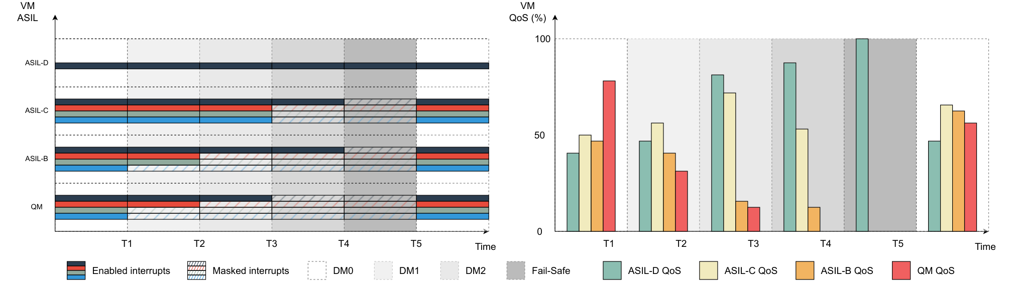
Figure 5 provides an illustrative example of the IRQ Coloring inner works. The setup comprises four VMs, with one representing a highly critical system (ASIL-D), two others simulating intermediate critical systems (ASIL-C and ASIL-B), and a non-critical system (QM). At the initial instant (T0-T1), four interrupts are assigned to each intermediate and lower criticality VM, and one interrupt is assigned to the higher criticality system, all of which are active.
After a given time interval, the hypervisor collects a series of events () that enable the computation of the QoS of each VM, which allows calculating the effect of interference (). Based on this value, the degradation mode is updated, masking two interruptions of the lower criticality VM. However, applying this degradation mode alone is insufficient to guarantee the requirements of the most critical VMs. Thus, the degradation mode is updated after another time period(T2). This process repeats until a fail-safe mode is reached (T4-T5), which involves suspending all non-critical VMs. Once the requirements of the most critical VM (ASIL-D) are satisfied, the interrupts of the medium and low critical VMs become active again. However, it’s important to note that this process must be carried out progressively, as explained earlier.
IV Implementation
Hardware Implementation We implemented and deployed the IRQ Coloring RTM on a Xilinx ZCU102 board featuring an Ultrascale+ ZU7EV SoC. The system has a quad-core Arm Cortex-A53 processor operating at 1.2GHz. CPUs have separate 32KiB L1 instruction and data caches and a shared 1MiB L2 cache. The cluster features the GIC-400 (GICv2). Nevertheless, it is possible to port the IRQ Coloring to a newer version of GIC, such as GICv3, since most of the IRQ Coloring RTM’s functionality relies on the GICD, which is also available in GICv3. However, some changes may be necessary as although the and registers exist in both GICv2 and GICv3, there are subtle differences in their register layout and functionality.
Software Implementation The implementation of the IRQ Coloring RTM consists of a thin layer of software that sits between the distributor and the CPU interfaces, built on top of the Bao hypervisor. The RTM uses two hardware components to track the performance of VMs and employs a time-based control system. The first component is the PMU of each CPU, which collects specific metrics to assess the QoS of each VM. The second component is the Generic Timer, which provides a time reference for the system and controls interrupt masking based on the established IRQ Coloring policy. To implement the IRQ Coloring, we assume a 1-1 mapping of virtual to physical CPUs. Therefore, each PMU collects the microarchitectural events of a single VM. PMU events, accessed via the MRS and MSR instructions, are used to compute the stages of the IRQ Coloring RTM. Once the computation is complete, all VMs mask the corresponding IRQs by manipulating the and registers from the GIC to set and clear interrupts.
The configurability of the IRQ Coloring RTM is crucial for its effectiveness, adaptability, and scalability. Thus, it is key to provide an easy-to-configure interface; however, the configuration process is not limited to the interface, as the IRQ Coloring masking policy also plays a vital role in ensuring proper distribution of interrupts among the VMs. The masking policy must be carefully configured, taking into account the varying performance requirements of the VMs, to ensure that critical interrupts are not delayed or lost. Moreover, the IRQ Coloring mechanism offers configurability in several hyperparameters. These include (i) the actuation period, which determines the frequency of actuation of the mechanism, (ii) the weight assigned to each PMU event, and (iii) the expected behavior of each VM (e.g., the optimal number of cache misses that match the native execution of the VM). While the fine-tuning of these parameters can further enhance the mechanism’s effectiveness in mitigating interference, the incorrect definition of these parameters, on the other hand, can lead to an incorrect actuation of the IRQ Coloring RTM. In order to refine the IRQ Coloring parameters, it is imperative to use a profiling tool that (i) enables the selection of microarchitectural events that better reflects the characteristics of the applications under consideration, (ii) as well as suggests the appropriate value for each reference parameter.
V Evaluation
In this section we describe the evaluation setup and present and discuss the evaluation results.
| ASIL-D | ASIL-C | ASIL-B | QM | |||||||||||
| IRQ | IRQ 0 | IRQ 1 | IRQ 2 | IRQ 3 | IRQ 0 | IRQ 1 | IRQ 2 | IRQ 3 | IRQ 0 | IRQ 1 | IRQ 2 | IRQ 3 | ||
| Dual-VM | Degradation Mode 0 | |||||||||||||
| Degradation Mode 1 | ||||||||||||||
| Degradation Mode 2 | ||||||||||||||
| Fail-Safe Strategy | ||||||||||||||
| Quad-VM Setup 1 | Degradation Mode 0 | |||||||||||||
| Degradation Mode 1 | ||||||||||||||
| Degradation Mode 2 | ||||||||||||||
| Fail-Safe Strategy | ||||||||||||||
| Quad-VM Setup 2 | Degradation Mode 0 | |||||||||||||
| Degradation Mode 1 | ||||||||||||||
| Degradation Mode 2 | ||||||||||||||
| Fail-Safe Strategy | ||||||||||||||
| Enabled IRQ | Masked IRQ | N.A. IRQ | ||||||||||||
V-A Methodology
Evaluation Setup. To assess the effectiveness of the IRQ Coloring RTM, the evaluation comprises two different use cases. The first use case involves two VM, each assigned one CPU. The first VM runs on a Linux OS and executes various suites of the Mibench benchmark. The second VM is intended for memory-intensive applications and aims to create contention at the last-level cache and system bus. This VM comprises four tasks, each triggered by a different interrupt generated by a hardware module deployed on the PL of the ZCU102. The second use case expands the evaluation to four VM - 1 CPU assigned to each VM. The critical VM runs a synthetic application that mimics the behavior of the MiBench Benchmark33 3 The evaluation was conducted targeting an (emulated) automotive use case, using Erika3 to set up the evaluation environment. At the time of this writing, we could not find a fully functional Mibench AICS Suite port for Erika3 RTOS. Thus, we could not use the original Mibench AICS Suite, which is ready-to-use for Linux. Therefore, an adaptation of the benchmark was required to make it compatible with Erika3. To achieve this, we performed a benchmark profiling process by collecting microarchitectural events, such as L2 cache accesses and bus accesses, during the execution of each benchmark. Based on this profiling, we reconstructed the benchmark so that the application would perform load and store operations to replicate the behavior of the original benchmark. We called this suite the ”Synthetic Mibench AICS Suite”., while the other three run memory-intensive applications. The objective is to measure the impact of increased number of irq-driven workloads on the performance of the higher criticality VMs and, in parallel, understand the intermediate guarantees of the IRQ Coloring RTM mechanism on the medium criticality VMs.
VM Workload. In our assessment of the IRQ Coloring RTM, we employed the well-established MiBench Automotive and Industrial Control System (AICS) Suite in the critical VM. This subset includes three of the most memory-intensive benchmarks, namely qsort, susan corners, and susan edges (Figure 1). We chose these benchmarks based on the observed profiling, i.e., these benchmarks are more susceptible to interference arising from cache and memory contention. In order to create interference among the VM (VMs), we deployed a baremetal application that continuously writes into a buffer equivalent in size to the last-level cache (LLC) (i.e., 1 MiB). Each VM is assigned four distinct interrupts, each of which activates a workload that writes to different segments of the buffer. To assess the impact of different workloads on the system’s performance, we divided the buffer into four sections: a 512KiB partition (equivalent to 50% of the LLC), a 256KiB partition (equivalent to 25% of the LLC), and two partitions of 128KiB each (equivalent to 12.5% of the LLC).
Measurement Tools. We use the Arm PMU to collect microarchitectural events to profile the benchmark execution. The chosen events comprise the number of L2 cache accesses and the number of bus accesses. Additionally, we leverage the ”perf” tool on the Linux operating system to measure the execution time of each benchmark.
IRQ Coloring RTM Configuration. To ensure the optimal performance of the IRQ Coloring RTM in mitigating interrupt interference, we made the following assumptions during our evaluation:
- 1.
The weights assigned to each microarchitectural event are equally distributed (50/50).
- 2.
- 3.
The interrupt masking on intermediate and non-critical VMs is based on the profile of each task, and the masking maps applied to each setup used in the Evaluation section are presented in Table I.
V-B IRQ Coloring RTM Microbenchmark
Figure 6 illustrates the IRQ Coloring RTM microbenchmark, which comprises the seven measuring points detailed in Table II. The first measuring point corresponds to the ”PMU Sampling”, which represents the time taken by the processor to collect performance data using the PMU. The next two measuring points correspond to different stages of the mechanism, with Stage 0 encompassing the QoS computation for each VM and Stage 1 corresponding to the decoding of the QoS value. The next three measuring points correspond to Stage 2, which involves different VMs synchronization, reference update, and interrupt masking operations. These stages are key for the IRQ Coloring RTM overall performance, and any inefficiencies or delays at this stage can significantly impact the overall system’s performance. The profiling results of the IRQ Coloring RTM indicate that the mechanism’s average execution time is 0.365 microseconds. However, due to the need to synchronize the different VMs, the maximum execution time observed is 0.782 microseconds. To put this into perspective, if the actuation period is 10 microseconds, the expected performance impact is 7.81%. In fact, the performance impact becomes negligible for sampling periods above 100 microseconds, resulting in a performance impact value below 0.8%, as depicted in Figure 7. Therefore, sampling the system at a frequency of 10 kHz would not have a significant performance impact.

|
Description | ||
|---|---|---|---|
| 1 | Time taken by the RTM for the PMU sampling. | ||
| 2 |
| ||
| 3 | Time taken by the RTM to decode the VM QoS values. | ||
| 4 |
| ||
| 5 |
| ||
| 6 |
| ||
| 7 |
|
V-C Results with Mibench Benchmaks - Dual-VM
We start by assessing the impact of interference mitigation on the high-criticality VM. The setup consists of two VMs running atop of hypervisor: (i) a Linux-based VM running the MiBench AICS Suite and (ii) a low-criticality (e.g., ASIL-QM) running a synthetic benchmark to create contention at the LLC. The evaluation process consists of comparing the execution of the MiBench AICS Suite benchmarks for six different system configurations: (i) solo benchmark execution (solo); (ii) solo benchmark execution with cache coloring enabled (solo+cc); (iii) solo benchmark execution with IRQ coloring enabled (solo+irqc); (iv) benchmark execution under interference (interf); (v) benchmark execution under interference with cache coloring enabled (interf+cc); and (vi) benchmark execution under interference with IRQ coloring enabled (interf+irqc).
Interference Mitigation Effect. The average results for 1000 runs are presented in Figure 8, and they are normalized to the native execution, where higher values indicate poorer performance. The empirical results demonstrate that memory-intensive applications, such as susan-c small, susan-e small, and q-sort small, can be significantly impacted by over 65% due to contention arising from the sharing of microarchitectural resources like the LLC and system bus. In the worst-case scenario, which is susan-c small, the execution time increases from 1.53ms to 3.27ms (2.13x when compared to the native execution). However, using interference mitigation techniques such as cache partitioning can help reduce the interference effect. By allocating 50% of the LLC to each VM, cache partitioning can significantly reduce interference and decrease the relative performance overhead to 1.62x for susan-c small, which is the most memory-intensive application, reducing the execution time to 2.48ms.
Furthermore, empirical results show that IRQ coloring is generally more effective in mitigating interference than the cache coloring technique, especially when the interference is very high, e.g., susan-c small, where the performance degradation is reduced from 2.13x to 1.02x, reducing the execution time from 3.27ms to 1.57ms. However, there are three cases where IRQ coloring is not as effective as cache coloring, i.e., basicmath-large, bitcount-small, and qsort-large. We investigated and we concluded that it is related to two major factors: (i) the profile of the benchmark, i.e., no memory-intensive and small execution time (few milliseconds); (ii) the weights of the control equation, i.e., 50-50, where the real benchmark has considerable more cache accesses than bus accesses (90-10).
Performance Impact. Leveraging techniques such as cache coloring can effectively reduce interference on multicore platforms. However, it is important to note that the performance degradation resulting from employing cache coloring due to LLC fragmentation is not negligible. For the susan-c small benchmark using cache coloring incurs an impact of 1.32x, increasing the execution time from 1.53ms to 2.02ms. In contrast, the IRQ coloring technique for the solo case has a near-negligible overhead ( 1.01x). Only for the qsort-small and susanc-small benchmarks is the overhead near 1.02x-1.03x, which in the case of the susanc-small results in an increase in the execution time from 1.53ms to 1.57ms. Overall, this results from the reduced execution time, as discussed in Section V.B.
V-D Results with Mibench Benchmaks - Quad-VM
We will now focus on evaluating the intermediate guarantees offered by the IRQ Coloring mechanism. Many interference mitigation techniques on multicore platforms, such as memory throttling, rely on suspending a CPU, which halts its activity along with the corresponding VM. IRQ Coloring aims at providing intermediate guarantees to medium-critical VMs by gradually reducing their workload to minimize interference with higher-critical VMs. To gather evidence on the intermediate guarantees provided by IRQ Coloring, we deployed two different systems, each with four VMs. During a 10-second period, we ran the workloads of each VM and counted the number of times each task was completed. With that, we compute the availability of each VM based on the number of completed tasks. For each setup, we assessed the throughput of each VM by collecting their execution alone with the different active tasks (solo), their execution over interference with the four VMs (interf), and the interference scenario with IRQ Coloring (interf+irqc).
Setup 1. The first setup encompasses four VMs, each assigned to one CPU. This setup emulates a realistic automotive use case, with ASIL-D and ASIL-C VMs running Erika RTOS and automotive-related benchmarks. In this case, due to the absence of baremetal support from the original MiBench AICS Suite, we ran the synthetic MiBench Suite. The ASIL-B and QM VMs intended to emulate memory-intensive applications and create contention at the last-level cache and system bus. These VMs comprise four tasks, each triggered by a different interrupt generated by a hardware module deployed on the PL of the ZCU102. Figure 9-(a) presents the workload bandwidth for the high-criticality VM, i.e., ASIL-D VM, and intermediate VMs, i.e., ASIL-C VM and ASIL-B VM. It is worth noting that no workload is completely stopped for both ASIL-C and ASIL-B VMs. For the ASIL-D and ASIL-C VMs, we highlight the additional bandwidth for both workloads (benchmarks) compared to the scenario under interference.
Setup 2. The second setup is an extension of Setup 1, designed to expand the workload of the ASIL-C VM. ASIL-D and ASIL-C VMs run Erika RTOS and the (synthetic) MiBench Suite. In this case, ASIL-C VM runs four benchmarks instead of two. The ASIL-B and QM VMs still consist of four tasks, each triggered by a different interrupt generated by the hardware module. Figure 9-(b) presents the workload bandwidth for the high-criticality VM, i.e., ASIL-D VM, and intermediate VMs, i.e., ASIL-C VM and ASIL-B VM. It is worth noting that, compared to the results of Figure 9-(a), the increased workload in the ASIL-C VM leads to a scenario where one of the benchmarks (susanc-small) presents less bandwidth than the scenario under interference.
VI Discussion
IRQ Coloring RTM QoS Calculation. The RTM calculates the QoS of each VM by taking a weighted average of only two microarchitectural events: L2 cache accesses and bus access cycles. However, it is vital to understand the optimal weight of each event for better control logic, as observed in the evaluation of benchmarks. Adding other microarchitectural events to the control equation logic may impact the performance overhead and interference mitigation effectiveness; thus, it would be interesting to perform such a study in the near future. Furthermore, another potential optimization would be the use of a static look-up table calculated by the IRQ DTT instead of a weighted sum in the control logic.
IRQ Coloring RTM QoS Reference Values. The IRQ Coloring RTM QoS reference values are static and unique (single) per VM. However, workload behavior can change significantly during execution (as we observe while reconstructing the synthetic MiBench AICS Suite). To address this, having a vector of reference values per VM per execution period would be beneficial. This means having multiple reference values per QoS element per workload period; however, this poses additional challenges in synchronization. Investigating the impact of vector length on performance overhead and intermediate guarantees would also be interesting.
IRQ Coloring RTM Actuation Period. The IRQ Coloring RTM Actuation Period is crucial for performance overhead and interference mitigation effectiveness, which affects intermediate guarantees. To determine the actuation period, we considered the benchmark profile and interference mitigation effectiveness from the preliminary set of experiments. To be conservative, we set the actuation period ten times smaller than the execution period of the smallest application of the most critical VM, following the Nyquist-Shannon sampling theorem. However, this period may not be optimal for intermediate VMs when the high-criticality VM is idle. Dynamic set options for the RTM actuation period should be explored.
Portability of IRQ Coloring. IRQ Coloring is implemented for Armv8-A platforms. However, it can be adapted to other platforms, including new Arm real-time processors (Cortex-R52) and RISC-V application processors (e.g., CVA6). Evaluating the effectiveness of the technique on these platforms would be valuable, especially for Cortex-R52, which lacks hardware primitives for cache partitioning, and for RISC-V, which presents hardware-software co-design opportunities.
VII Related work
Several memory interference mitigation mechanisms have been put forth by the real-time research community. Those COTS-applicable mainly focus on shared LLC or DRAM bank partitioning, regulating memory bandwidth, or co-scheduling. Although mainly designed for OSs, these techniques have also been applied in hypervisors, but none leverage interrupt masking to achieve their end-goals.
Cache Partitioning. Cache partitioning [25] consists of assigning subsets of the LLC to a specific workload and can be implemented in two main ways. Cache locking requires hardware assistance to restrict the eviction of selected cache lines, while cache coloring leverages virtual page number and cache index overlap to partition cache sets. Colored Lockdown [26] combines coloring and locking. Other works have proposed dynamic re-coloring schemes [27, 28, 29]. Cache coloring has been implemented in several hypervisors such as Bao [4], Jailhouse [13], and XVisor [14].
DRAM Bank Partitioning This technique leverages the parallelism in DRAM bank access to avoid contention among different workloads. PALLOC [16] proposes an OS-level DRAM bank-aware memory allocator to avoid bank sharing among cores. In [13], authors combine DRAM bank and cache coloring into a single allocator at the hypervisor level. Similar ideas have been transposed to low-end microcontrollers [30].
Memory Bandwidth Regulation. By limiting the memory bandwidth of partitions, one can ensure bandwidth guarantees for higher-criticality workloads. Memguard [31] throttles cores based on a memory bandwidth budget allocation, using performance monitoring counters to measure memory accesses and trigger the mechanism. In [14], authors apply Memguard at the hypervisor level, and Crespo et al. [32] follow a similar line by applying control theory to implement a feedback control scheme. Others have analyzed the efficacy of QoS regulators in minimizing IO-originated DRAM contention [33, 19].
Co-scheduling. The main insight of this approach is to co-schedule workloads in such a way that minimizes interference. RT-Gang [34] proposes a novel gang-scheduling policy combined with memory bandwidth regulation. The PRedictable Execution Model (PREM) [35] divides tasks into memory access and compute phases and co-schedules them accordingly so that the former do not overlap for critical workloads. Kloda et al. [13] apply this idea at the hypervisor level.
VIII Conclusion
In this paper, we presented the design, implementation, and evaluation of IRQ coloring. This mechanism aims to minimize interrupt-generated interference and provide intermediate guarantees for medium-criticality workloads. The core concept consists of deactivating ”colored” interrupts if the QoS of critical workloads drops below a specific threshold. The prototype was evaluated on a high-performance multicore platform (Xilinx ZCU102). Results demonstrated negligible performance overhead, i.e., 1% for a sampling period of 100 microseconds, and reasonable throughput guarantees for medium-critical workloads. We believe that IRQ coloring is orthogonal to other state-of-art techniques, presents predictability and intermediate guarantees advantages, and can be implemented in the new generation of real-time Arm processors (e.g., Cortex-R52).
Acknowledgment
This work has been supported by Huawei Pisa Research Center and by FCT - Fundação para a Ciência e Tecnologia grants 2022.13378.BD, 2020.04585.BD, SFRH/BD/138660/2018. This work has also been partially supported by FCT within the R&D Units Project Scope UIDB/00319/2020.
References
- [1] J. P. Cerrolaza et al., “Multi-core devices for safety-critical systems: A survey,” in ACM CSUR, vol. 53, no. 4, 2020.
- [2] S. Pinto et al., “LTZVisor: TrustZone is the Key,” in ECRTS, vol. 76, 2017.
- [3] G. Gracioli et al., “Designing Mixed Criticality Applications on Modern Heterogeneous MPSoC Platforms,” in ECRTS, vol. 133, 2019.
- [4] J. Martins et al., “Bao: A Lightweight Static Partitioning Hypervisor for Modern Multi-Core Embedded Systems,” in Workshop on NG-RES, vol. 77, 2020.
- [5] R. Ramsauer et al., “Look Mum, no VM Exits! (Almost),” in Workshop on OSPERT, 2017.
- [6] P. Burgio et al., “A software stack for next-generation automotive systems on many-core heterogeneous platforms,” in Microprocessors and Microsystems, vol. 52. Elsevier, 2017.
- [7] R. Mancuso et al., “Real-time cache management framework for multi-core architectures,” in RTAS, 2013.
- [8] J. Abella et al., “WCET analysis methods: Pitfalls and challenges on their trustworthiness,” in SIES, 2015.
- [9] F. J. Cazorla et al., “Probabilistic worst-case timing analysis: Taxonomy and comprehensive survey,” in ACM CSUR, vol. 52, no. 1, 2019.
- [10] F. J. Cazorla et al., “Proartis: Probabilistically analyzable real-time systems,” in ACM TECS, vol. 12, no. 2s, 2013.
- [11] J. Martins et al., “Shedding Light on Static Partitioning Hypervisors for Arm-based Mixed-Criticality Systems,” in RTAS, 2023.
- [12] M. Bechtel et al., “Denial-of-service attacks on shared cache in multicore: Analysis and prevention,” in RTAS, 2019.
- [13] T. Kloda et al., “Deterministic memory hierarchy and virtualization for modern multi-core embedded systems,” in RTAS, 2019.
- [14] P. Modica et al., “Supporting temporal and spatial isolation in a hypervisor for arm multicore platforms,” in ICIT, 2018.
- [15] H. Kim et al., “Predictable shared cache management for multi-core real-time virtualization,” ACM TECS, vol. volume 17, 2017.
- [16] H. Yun et al., “PALLOC: Dram bank-aware memory allocator for performance isolation on multicore platforms,” in RTAS, 2014.
- [17] H. Yun et al., “Memory access control in multiprocessor for real-time systems with mixed criticality,” in ECRTS, 2012.
- [18] F. Farshchi et al., “BRU: Bandwidth Regulation Unit for Real-Time Multicore Processors,” in RTAS, 2020.
- [19] M. Zini et al., “Profiling and controlling I/O-related memory contention in COTS heterogeneous platforms,” in Software: Practice and Experience, vol. 52, no. 5, 2022.
- [20] A. Gordon et al., “ELI: Bare-metal performance for I/O virtualization,” in ACM SIGPLAN Notices, vol. 47, no. 4, 2012.
- [21] D. Costa et al., “IRQ Coloring: Mitigating Interrupt-Generated Interference on ARM Multicore Platforms,” in Workshop on NG-RES, 2023.
- [22] M. R. Guthaus and Rothers, “Mibench: A free, commercially representative embedded benchmark suite,” in IEEE WWC-4, 2001, pp. 3–14.
- [23] H. Nyquist, “Certain topics in telegraph transmission theory,” in Transactions of the American Institute of Electrical Engineers, vol. 47, no. 2, 1928.
- [24] C. E. Shannon, “Communication in the presence of noise,” in Proceedings of the Institute of Radio Engineers, vol. 37, no. 1, 1949.
- [25] G. Gracioli et al., “A Survey on Cache Management Mechanisms for Real-Time Embedded Systems,” in ACM CSUR., vol. 48, no. 2, 2015.
- [26] R. Mancuso et al., “Real-time cache management framework for multi-core architectures,” in RTAS, 2013.
- [27] Y. Ye et al., “COLORIS: A dynamic cache partitioning system using page coloring,” in PACT, 2014, pp. 381–392.
- [28] M. Xu et al., “vCAT: Dynamic Cache Management Using CAT Virtualization,” in RTAS, 2017, pp. 211–222.
- [29] S. Roozkhosh et al., “The Potential of Programmable Logic in the Middle: Cache Bleaching,” in RTAS, 2020.
- [30] S. Pinto et al., “Virtualization on TrustZone-enabled Microcontrollers? Voilà!” in RTAS, 2019.
- [31] H. Yun et al., “MemGuard: Memory bandwidth reservation system for efficient performance isolation in multi-core platforms,” in RTAS, 2013.
- [32] A. Crespo et al., “Hypervisor-Based Multicore Feedback Control of Mixed-Criticality Systems,” in IEEE Access, vol. 6, 2018.
- [33] A. Serrano-Cases et al., “Leveraging Hardware QoS to Control Contention in the Xilinx Zynq UltraScale+ MPSoC,” in ECRTS, 2021.
- [34] W. Ali et al., “RT-Gang: Real-Time Gang Scheduling Framework for Safety-Critical Systems,” in RTAS, 2019.
- [35] R. Pellizzoni et al., “A Predictable Execution Model for COTS-Based Embedded Systems,” in RTAS, 2011.
