Unified Adversarial Patch for Visible-Infrared Cross-modal Attacks in the Physical World
Abstract
Physical adversarial attacks have put a severe threat to DNN-based object detectors. To enhance security, a combination of visible and infrared sensors is deployed in various scenarios, which has proven effective in disabling existing single-modal physical attacks. To further demonstrate the potential risks in such cases, we design a unified adversarial patch that can perform cross-modal physical attacks, achieving evasion in both modalities simultaneously with a single patch. Given the different imaging mechanisms of visible and infrared sensors, our work manipulates patches’ shape features, which can be captured in different modalities when they undergo changes. To deal with challenges, we propose a novel boundary-limited shape optimization approach that aims to achieve compact and smooth shapes for the adversarial patch, making it easy to implement in the physical world. And a score-aware iterative evaluation method is also introduced to balance the fooling degree between visible and infrared detectors during optimization, which guides the adversarial patch to iteratively reduce the predicted scores of the multi-modal sensors. Furthermore, we propose an Affine-Transformation-based enhancement strategy that makes the learnable shape robust to various angles, thus mitigating the issue of shape deformation caused by different shooting angles in the real world. Our method is evaluated against several state-of-the-art object detectors, achieving an Attack Success Rate (ASR) of over 80%. We also demonstrate the effectiveness of our approach in physical-world scenarios under various settings, including different angles, distances, postures, and scenes for both visible and infrared sensors.
Index Terms:
Adversarial examples, Cross-modal attack, Visible-Infrared, Shape optimization, Adversarial patches, Physical world.I Introduction
With the found vulnerability of Deep Neural Networks (DNNs) against adversarial examples [1], DNNs’ security has become a serious problem, which may cause target evasion in the physical world[2, 3, 4, 5]. Leveraging this property, researchers develop stealth technology to evaluate how robust DNNs are in real-world systems through physical attacks. In real life, many safety-critical tasks such as security monitoring, autonomous driving, etc., use both visible light sensors and thermal infrared sensors to perform object detection. The round-the-clock application is made possible by the combination[6, 7], which provides detailed texture information during the day under the visual modality and the target’s thermal distribution at night under the infrared modality. Therefore, creating a cross-modal physical attack to trick both visible and infrared object detectors simultaneously is a critical step for robustness evaluation in such multi-modal imaging circumstances.
However, existing physical attacks are generally restricted to single modality. Some studies[8, 9, 10, 11, 12] can circumvent detection in the optical modality, while some studies[4, 5, 13, 14] achieve evasion under infrared object detectors. Those physical attacks cannot fool multi-modal object detectors at the same time due to different imaging mechanisms. In particular, infrared sensors cannot capture the perturbations generated in the optical modality, and vice versa, the imaging of visible light domain is unaffected by changes in the object’s thermal radiation. In the digital world, there also exist some cross-modal attacks[15, 16, 17], but their methods mainly focus on altering the image pixels or point clouds data after sensors’ imaging and ignore the imaging process of diverse mechanisms across sensors, which causes limited effectiveness in the physical world.

Based on the above discussions, a unified cross-modal attack in the physical world with the consideration of imaging differences is developed in this paper to fill in the gap of this field, as shown in Table I. In general, the root cause of limited accessibility of cross-modal physical attacks is the absence of properties that may function in several modalities. Inspired by[13] and [18], we utilize adversarial patches [19] with shape optimization to conduct attacks. The changes of patches’ shape can be effectively captured by both visible and infrared sensors as a universal characteristic for diverse imaging mechanisms and thus, this shape-based method is suitable for performing cross-modal attacks. However, three core challenges still remains to meet our goal: (1) The current shape models are either heteromorphic [18] or change-limited [13], leading to difficult physical implementation or poor attacks because of finite searching space and possible deviations. So how to design a flexible shape optimization method while keeping shapes’ smoothness is the first challenge. (2) During the original optimization for the unified shape, the detection scores usually drop at an inconsistent rate, which may lead to significantly effective performances in one modality but fail in another. Therefore, how to balance the performance of the two object detectors from different domains is the second challenge. (3) When capturing the patch in the real world, a large shooting angle of the camera may lead to a shape deformation of the patch in the photo, which will degrade the performance of our shape-based physical attacks. Thus, how to optimize a robust shape to various angles is the third challenge.
| Digital world | Physical world | |
|---|---|---|
| Single-modal | [20],[21],[22],[23], | [4],[5],[14], |
| [24],[25], etc. | [26], [27], [28], etc. | |
| Cross-modal | [15],[16], etc. | Ours |
To address these issues, firstly, a novel boundary-limited shape optimization method is designed to generate compact and smooth shapes that are simple to execute in the real world, meanwhile it can provide a wider search space to flexibly find the optimal shape for a successful cross-modal attack. Secondly, we introduce a score-aware iterative evaluation mechanism that can direct the patch to iteratively reduce the predicted scores of the multi-modal sensors with concurrent validity, in order to balance the fooling degree of visible and infrared detectors during shape optimization process. Thirdly, to mitigate the issue of shape deformation due to different shooting angles, we propose an Affine-Transformation-based enhancement strategy to simulate the various patch shape’s deformations along with the camera angles’ change, and then search for the optimal shape that has the least drop of the attack performance under different deformations. We finally demonstrate the effectiveness of our cross-modal adversarial patch against visible and infrared pedestrian detectors in Figure 1, where we only need to print and crop the simulated results in the digital world with insulation materials for patches in the physical world. The implementation is simple and convenient. The code can be found in https://github.com/Aries-iai/Cross-modal_Patch_Attack.
In summary, the contributions of this paper are as follows:
- •
We propose a unified adversarial patch to perform cross-modal attacks. To the best of our knowledge, it is the first work to simultaneously evade visible detectors and infrared detectors in the physical world.
- •
We design two novel techniques: boundary-limited shape optimization and score-aware iterative evaluation, to generate feasible patches in the digital world that can balance the multi-modal object detectors. Moreover, our framework is scalable and can be easily integrated with the patch’s position for a joint optimization.
- •
We mitigate the issue of shape deformation due to different shooting angles in the physical world and propose an Affine-Transformation-based enhancement strategy to make the learnable shape robust to various angles.
- •
We evaluate our unified cross-modal adversarial patches on the pedestrian detection task in both the digital and physical worlds. Experimental results demonstrate that our unified cross-modal adversarial patches can perform well under various angles, distances, postures, and scenes. We also apply our method to the vehicle detection task to show its good generalization ability.
This journal paper is an extended version of our ICCV paper [29]. Compared with the conference version, we have made significant improvements and extensions in this version versus the following aspects: (1) We further analyze the challenge of applying shape-based attacks in the physical world, and find that shape deformation will happen in the photo when meeting large shooting angles of the camera, which will degrade the performance of physical attacks. For that, we design an Affine-Transformation-based enhancement strategy to mitigate this issue. The technical details are introduced in Section III-D1, and the corresponding experiments are given in Section IV-B2. (2) We show that our shape-based attack method is easy to combine the patch’s position to jointly improve the attack performance, which verifies the good flexibility of our framework. The technical details are introduced in Section III-C4, and the corresponding experiments are given in Section IV-A4. (3) Except for pedestrian detection, we extend our method to attack vehicle detection task in Section IV-B3, which demonstrates the good generalization ability of our method. (4) We add new experiments about parameter tuning, comparisons with SOTA methods, attacking various object detectors in Section IV-A1, Section IV-A5, Section IV-A6, respectively. (5) We polish the whole paper and add or rewrite some sections (like Sections I, II-B, II-C, IV, etc.) to make the paper easy to understand. We believe these modifications can significantly improve the paper’s quality.
The rest of this paper is structured as follows: Section 2 reviews the related works. Section 3 describes the detailed method for our unified adversarial patch. Section 4 presents and analyzes the experimental results. Section 5 concludes the paper.
II Related Works
II-A Adversarial Attacks in the Physical World
Since Kurakin et al. [24] prove the feasibility of adversarial attacks in the real world, numerous physical attack methods for various purposes have been proposed. In the visible domain, Sharif et al. [26] design adversarial glasses to deceive face recognition systems, Eykholt et al. [30] create adversarial graffiti to mislead automatic driving tasks, and Xu et al. [3] develop adversarial T-shirts to evade person detectors. Different from traditional Lp-norm based attacks which need to constrain the perturbation magnitude, these methods are based on adversarial patches [31]. In the infrared domain, Zhu et al. propose adversarial bulbs [4] and invisible clothes [5] to attack infrared pedestrian detectors, respectively using extra heat sources and QR code patterns. The two methods are effective but very complex to implement in the real world. For this reason, Wei et al. [14] propose a convenient adversarial infrared patch with learnable shapes and positions, it has good generalization, which can not only attack pedestrian detectors but also vehicle detectors.
However, these methods only focus on single modality, and cannot work well for cross-modality physical attacks.
II-B Shape Optimization in Adversarial Attacks
Given the attack feasibility of early adversarial patches with fixed common shapes, some studies have looked further into patch’s shape for adversarial attacks. Chen et al. [18], for instance, propose a deformable patch representation determined by a central point and multiple rays, making the deformable shape overly harsh and unnatural. Their work only focuses on image classification tasks and patch’s content optimization is still required. Then, Wei et al. [13] suggest a hotcold block based on Warming Paste and Colding Paste to attack infrared object detectors, but the deformation is limited by the manually set nine-square-grid states, which significantly decreases the search space of shape and attack performances for challenging attack goals. Besides, it relies on too much blocks, some of which are at unstable positions and may cause performance degradation. In adversarial infrared patches [14], their shape modeling is essentially determined by a designed aggregation regularization. Although this method has made a good trade-off between the attack effect and shape’s physical feasibility compared to the previous two methods, we still find that it overlooks the edge smoothing of infrared patches, and thus poses bad effects on physical implementation to some extent.
Unlike previous methods that use either nine-square-grid states [13] or polygonal shapes with a central point and rays [18], we propose a novel approach that uses multiple anchor points and spline interpolation to generate smooth and flexible shape edges. This enables us to explore a larger search space and achieve better performance in the cross-modal physical attacks.
II-C Cross-modal Adversarial Attacks
Some studies have explored cross-modal attacks on multi-modal detection systems, which are mainly for autonomous vehicles based on RGB cameras and LiDAR sensors for perception, using 2D image data and 3D point clouds. For example, Abelfattah et al.[15] propose a cross-modal and physically realizable attack that places an adversarial 3D object on top of a car in a 3D scene and renders it to both point clouds and RGB images using differentiable renderers, as shown in Figure 2 (top row). The object’s shape and texture are trainable parameters that can be manipulated adversarially. Tu et al.[16] also propose a cross-modal and physically realizable attack that inserts a textured mesh onto the car’s roof, perturbing both shape and texture information for both RGB images and point clouds, as shown in Figure 2 (bottom row). They claim that such placement can be realized in the real world.


But the existing methods only claim to be “physically realizable”, which have not been tested in the real world. They only demonstrate their methods in a simulated 3D environment, and rely on the consistency of adversarial 3D objects across modalities to prove their physical realizability. However, such adversarial 3D objects are difficult to produce and impractical to place over a vehicle. Therefore, “physically realizable” only means theoretically feasible, not actually applicable.
In contrast to the existing methods that only ensure “physically realizable” attacks in simulation, we present the first cross-modal physical attack that actually works on the object in the real world. Moreover, we target visible-infrared cross-modal attacks, while [15] and [16] target visible-LiDAR cross-modal attacks, which is another major difference between our work and theirs. To the best of our knowledge, none of the previous methods can simultaneously attack both visible and infrared modalities in reality.
III Methodology
In this section, we choose pedestrian detection as the target task to introduce the details of our method.
III-A Problem Formulation
In the pedestrian detection task, given a clean visible image and a clean infrared image , the goal of a unified cross-modal adversarial attack is to make the visible detector and infrared detector simultaneously unable to detect the pedestrian in the perturbed visible image and perturbed infrared image . The formulation can be expressed as follows:
| (1) |
where and represent the confidence scores of detected pedestrians in the visible modality and infrared modality, and is a pre-defined threshold.
The perturbed visible image and the perturbed infrared image with the unified adversarial patch can be generated as Eq.(2) and Eq.(3):
| (2) |
| (3) |
where is Hadamard product, is a mask matrix used to constrain the shape and location of the cross-modal patches on the target object, denotes a cover image used to manipulate , denotes a cover image used to manipulate . The values of these two cover images are obtained by the visible sensor and infrared sensor shooting the unified insulation material in the physical world. The unified patches can be described as all the regions where .
In the real application, we use the aerogel material to implement our unified adversarial patch. When infrared sensor shoots, it will show good insulation effects, and thus can change the thermal distribution of the target pedestrian. When visible sensor shoots, its color is white and can show a difference with the pedestrian. Based on this, our method optimizes a cross-modal to learn an adversarial shape, finally working well in both modalities.
III-B Shape Representation
To model a shape, we need to determine the shape representation. For that, we first define some points as the basic elements. Then we connect these anchor points to construct the contour, representing our shape. Here are the details.
Multi-anchor Representation: Unlike Chen et al. [18] using a central point and corresponding rays to form a polygon contour, we only use points, distributing multiple anchor points on the patch contour. Then, we can directly adapt the patch contour’s shape by changing the coordinates of the points. Owing to the design of multi-anchor representation, we can have more flexible shape variations and a broader search space.
We illustrate this process in Figure 4 (a), where points in the dotted line denote the initialized location. The arrows show the changed direction for some points. We can adjust the coordinates of the points to control the movement of each point and thus, the direction of our points’ movement will not be limited.

Smooth Spline Connection: To ensure shapes’ naturalness, we use centripetal Catmull–Rom spline [32] to connect such anchor points. The process of spline can be formulated as follows:
As shown in Figure 4 (b), to generate a curve segment between and , we will use four anchor points and a centripetal Catmull-Rom spline function [32]. With the centripetal Catmull-Rom spline function, first, we can ensure that a loop or self-intersection doesn’t exist within a curve segment. Second, a cusp will never occur within a curve segment. Finally, it can also follow the anchor points more tightly. can be formulated as follows:
| (4) |
When curve segments are combined, the patch contour can be written as:
| (5) |
With being closed, we can easily obtain :
| (6) |
After Eq.(6), we can represent the patch’s shape. The detailed formula for this process can be found in Supplementary Material.

III-C Shape Optimization for Cross-modal Attacks
In practice, the details of and are usually unknown to the adversary, so it is intractable to optimize the anchor points via a gradient-based optimization method. Considering this background, we carry out a score-based black-box attack by querying the object detector to obtain the confidence scores of detected pedestrians. From the above, we formulate the whole unified cross-modal attacks into the Differential Evolution (DE) framework[33].
III-C1 Formulation Overview Using DE
The Differential Evolution (DE) consists of four parts: starting from an initial population, using the crossover and mutation to generate the offspring population, making the fittest survive according to the fitness function, and finding the appropriate solution in the iterative evolution process.
In our case, a population represents the anchor points . Given the population size , the -th generation solutions is represented as:
| (7) |
where is the -th patch’s shape, and represents the -th anchor point of in the -th generation. and together make up the feasible region , which is the moving range of the -th anchor point in each patch shape.
In the generation of DE, the solution is achieved via crossover, mutation, and selection based on . A fitness function is applied on to evaluate its attack effectiveness. During this process, the fitness function only utilizes the confidence scores of object detectors, therefore, we can conduct score-based black-box attacks. We will give the detailed definition of feasible region in Section III-C2, and fitness function in Section III-C3.
III-C2 Boundary-limited Shape Optimization
Obviously, if there is no boundary restriction for the anchor points during the crossover and mutation, some bad situations will occur during shape optimization, as shown in Figure 5 (d, e, f), such as boundary line crossings (d), anchor points stuck in narrow places (e), and anchor points outside the human body region (f). To address these issues, we propose a novel boundary-limited shape optimization, which not only provides sufficient transformation space, but also ensures the effectiveness of each shape.
As shown in Figure 5 (b), the shaded part is exactly the feasible region of the anchor point . Specifically, the two adjacent equidistant lines, the inner circle’s edge and the outer border together make up of its boundary. Figure 5 (c) presents us with an example of effective deformation. Next, we will give how to construct the boundary and the method of judging whether a point is inside or not.
We first divide a circle with a given radius and a circle center into sharp-angled sectors by equidistant lines . equal points are the intersection of equidistant lines and the circle, and as shown in Figure 5 (b), the anchor point is the midpoint of and , which can be formulated as follows:
| (8) |
For the anchor point , it lies in the sharp-angled sector region wrapped by two adjacent lines and . and represent the directed distance from the anchor point to the line and shown in the Figure 5 (a). Therefore, with the line function and , we can formulate and as follows:
| (9) |
where and are the denominators of the point-to-line distance formula.
From the Figure 5 (b), we can vividly find that since the anchor point ’s feasible region is a sharp-angled sector, if is inside its own region, for the angle between them is obtuse, while if is outside its own region or exactly on the boundary line, . With inside its own region, we can effectively avoid boundary line crossings in Figure 5 (d) caused by spline interpolation’s need for a given order.
Then, to prevent points from falling into narrow places as Figure 5 (e), we set an inner circle with a given radius inside the initial circle, and anchor points are not allowed to move into the inner circle. Specifically, we can judge by the distance from the anchor point to the center . When , the anchor point will not be inside the inner circle. The is computed as follows:
| (10) |
After that, we still need to ensure that the generated patch is not outside the effective area of the human body as shown in Figure 5 (f), so we scale the detection box output in a certain proportion as the outer border. The region inside the outer border can be represented as follows:
| (11) |
where are outer border’s vertex coordinates.
Finally, we combine the above limits as follows:
| (12) |
where means that the anchor point is inside the feasible region and means the anchor point is outside .
III-C3 Score-aware Iterative Evaluation
In cross-modal attacks, a good attack effect of a single modality is ineffective, while it is common to have unbalanced attack effects in the two modalities. If this situation is not improved, it may give the attacker false signals about the progress of the attack. Thus, to balance the fooling degree between visible detector and infrared detector during the optimization process, we propose a score-aware iterative evaluation, guiding the adversarial patch to iteratively reduce predicted scores of the multi-modal sensors.
For the sake of simplicity of expression, here we denote as . To evaluate the fitness value of , we first use methods in Section III-B to transform into a patch mask , then , are produced based on Eq.(2), Eq.(3). The fitness funtion can be formed as follows:
| (13) |
where is a weighted factor, reflect the current progress towards the success of attack (the larger, the closer to success). can be formalized as:
| (14) |
| (15) |
where is the confidence score of in the visible pedestrian detector, is the confidence score of in the infrared pedestrian detector. and are similar to and .
From Eq.(14) and Eq.(15), we can easily know and measure the progress to success of the cross-modal patch attack in the visible and infrared modality respectively. Both of them can help patches evolve in the corresponding modality. However, if we only make use of a single one, it will be certain to cause unbalanced phenomena, not an effective cross-modal attack. To solve this issue, we use Eq.(13) to combine and . Based on our , the good performance only in a single modality will not achieve a high value of fitness because we take the worse one of and as a standard. Additionally, considering the difference of attack difficulty in the initial stage and later stage, we use instead of a linear function. Based on the above settings, we will eventually encourage it to iteratively evolve in the direction of reducing confidence scores as much as possible while maintaining the balance of cross-modalities.
III-C4 Combined with Position Optimization
In the previous section of shape representation, a patch’s shape is determined by anchor points, which can be directly adapted by changing coordinates of those points, while the initial coordinates and feasible regions of the anchor points still depend on a pre-set central point and in this way, it will determine the final pasting position of the whole patch. However, according to Wei et al. [11], the optimized patch with the fixed position tends to be the best only in the current local part, and there may exist a more effective region in the global. Thus, it is also necessary to verify the position factor to our unified adversarial patch.
In our case, since position is also one of the major parameters on the patch attack, it is natural to think of optimizing anchor points’ positions along with the initial central point, achieving simultaneous optimization of patch’s shape and position. Different from Wei et al. [13]’s method, which performs adjustment by gradient, we only need to add the horizontal and vertical coordinates of the central point to the set of the point coordinates of the characterized individual. Taking the individual as an example, we denote in the previous definition, then we combine the central point with the point set to represent the new individual . At this moment, is denoted as follows:
| (16) |
Finally, we successfully take the exploration of patch’s position into account and achieve joint optimization under the cross-modal DE algorithm. Designed comparison experiments prove that adding the attribute “position” into the optimization process can truly improve the final attack performance and the specific results are shown in Section IV-A4.
The overall algorithms for cross-modal attacks and unified patches’ generation are summarized in Algorithm 1, 2, and the whole illustration for this framework is given in Figure 3.

III-D Transfer to the Physical World
III-D1 Affine-Transformation-based Enhancement Strategy
Considering that when camera shoots the patch with a large shooting angle, the patch’s shape will show a deformation, we need to ensure the versatility of the unified adversarial patch for multiple angles. In other words, our patch should explore the shape with good attack retention under some deformations. Towards this goal, we combine perspective transformation with human pose estimation to obtain objects with patches at different angles, and then utilize such multi-angle data to optimize our patch.
Specifically, in the first step, to perform a more accurate perspective transformation, we need to find relatively fixed reference points, which can help us compute the better homography matrix used in the transformation. Fortunately, due to the objects being pedestrians, keypoints of human body can greatly meet our requirements. So, we take human pose estimation[34] to extract such keypoints. Specifically, this method first trains a face detector to localize the human body based on the observation that the strongest signal of the neural network at the torso position is the face. Next, it predicts the midpoint of a person’s hip, the radius of the outer circle of the whole person, and the tilt angle of the line connecting the midpoint of the shoulder and hip to locate 33 keypoints from the nose to the left foot, which well represents a human body structure.
After obtaining the source keypoints and the target keypoints , we could utilize such point pairs to estimate the homography matrix . However, if not all of the point pairs (source keypoints, target keypoints) fit the rigid perspective transformation, which means that there exist some outliers, this initial estimate will be poor. So, we use the RANSAC [35] method to select the best subset from the point pairs for the initial estimation. To be detailed, the method RANSAC tries many different random subsets of the corresponding point pairs (four pairs each), estimates the homography matrix using this subset and then computes the quality of the computed homography, which is the number of inliers. The criteria for outliers are as follows:
| (17) |
where is a function to convert points from homogeneous coordinates back to Euclidean coordinates and is a pre-set threshold for distinguishing outliers and inliers in the RANSAC method [35].
With a good initial estimation, we then approximate the by minimizing the back-projection error rate. can be formulated as follows:
| (18) |
Then, the back-projection error is computed like below:
| (19) |
Next, we can use such an optimal homography matrix to transform a frontal mask into an at different angles as:
| (20) |
Finally, according to Eq.(2) and Eq.(3), adversarial samples with patches under different angles can be generated. Taking the adversarial samples in a left-skewed view as an example, they can be represented as follows:
| (21) |
| (22) |
where is a transformed mask at a left-skewed angle. ’s generation is similar to .
After obtaining new multi-angle adversarial samples, we can design a joint fitness function like Eq.(13) to enhance our unified patches’ multi-angle attack performance in the physical world. With the individual , the joint fitness function can be formulated as follows:
| (23) |
where is a set of the current progress towards the attack success in multiple angles. With representing adversarial samples generated based on the individual , can be represented as follows:
| (24) |
For simplicity, we here only add two additional angles, actually, multiple different angles can be considered to augment the set .
III-D2 Physical Implementation
After obtaining the optimal shape, we start to transform algorithm-generated digital patches into physical patches with the aerogel material. Specifically, we first scale the obtained patch according to its size in the real world and print it. Then, we use scissors to equally cut out the optimal shape on the material. And in the last, we use the velcro sticker to fix it at corresponding position of the human body for performing a physical attack. The whole process is demonstrated in Figure 7.

IV Experiments
IV-A Simulation of Physical Attacks
Dataset: We conduct experiments using the LLVIP dataset [36] to simulate physical attacks. The LLVIP dataset provides perfectly synchronized images in both visible and infrared modalities, and we customize the parts containing pedestrians in the images, following the approach used in [4] and [5]. The dataset consists of 3,784 images in the training set and 1,220 images in the test set. We select 120 images from the test set that the target model could recognize with high accuracy as the final samples to be attacked, resulting in a baseline clean Average Precision (AP) of 100%.
Target detector: To evaluate the effectiveness of our proposed approach for pedestrian detection, we select several mainstream detectors, including YOLOv3 [37], YOLOv5, YOLOv7[38], Faster RCNN [39], EfficientDet[40], and RetinaNet[41]. For each detector, we use the officially pre-trained weights as the initialized weights and then retrain the model on the training dataset. These models are then used as the target models in our attack process.
Metrics: We use Attack Success Rate (ASR) and Average Precision drop (AP drop) as the metrics to evaluate the performance of our physical attacks. To highlight the effectiveness of simultaneously attacking two modalities, we adopt a unique cross-modal ASR, which measures the ratio of successfully attacked images under both visible and infrared modalities out of all the test images. The AP drop metric is used to show the variation in Average Precision before and after the attacks.
Implementation: As we use the DE algorithm, we set the number of the initial population as , and the epochs of evolution as . All hyperparameters are verified on the validation set.
IV-A1 Hyperparameter Tuning
In this section, we tune hyperparameters against YOLOv3 model.
Patch number. As one of the most directly adjustable hyperparameters, patch number may have an impact on the attack performance. Therefore, we need to explore whether and how it is related to the attack performance. Figure 8 (a) vividly shows that as the number of patches rises, both ASR and AP drop increase with our expectation. However, considering that our attack method has achieved acceptable results with two patches, and three patches would bring more occlusion, we finally decide to choose the patch number 2 as the main evaluation option.

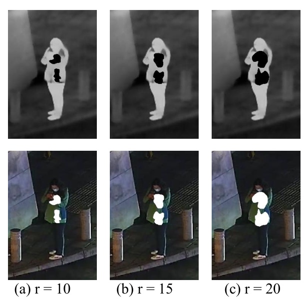
Patch size. In our method, the radius of the initial circle affects the size of the patch to some extent. To explore the impact of patch size on attack performance, we set 10, 15 and 30 for . The corresponding quantitative results are shown in Figure 8 (b), where we can see that though the ASR goes up as the patch size increases, our method can still achieve a competitive result with a small patch area, like an ASR of 66.67% with the radius . Additionally, we measure the percentage of patches in the pedestrian area i.e. “Occlusion Rate”. The higher the occlusion rate, the easier it is to cover non-effective areas, such as the human head region, as seen in Figure 9 (c). Therefore, to get a trade-off between attack performance and feasibility, we finally choose a radius of . Some examples of different patch sizes are shown in Figure 9.
Epochs. The epochs represent the maximum number of evolution to a single image. Thus, to explore the sensitivity of our method to time, we set epochs as 150, 200, 300. As Figure 8 (c) shows, though increasing evolution times can help unified adversarial patches improve themselves, its time efficiency (i.e. the countdown of time cost) has rapidly decreased. For example, when we compare the phase of [200, 300] with the phase of [150, 200], we use nearly two times extra epochs but only obtain a similar increase in ASR. Therefore, to make a trade-off between the effect and the time efficiency, we finally determine the number of epochs as 200.
Population Number. The number of populations affects the population diversity. A small number of populations means that the populations do not differ much and are easy to fall into the local optimal solution, but this does not mean that a larger number of populations is better. Actually, the larger the number of populations, the more difficult it is to converge and the lower the time efficiency. From Figure 8 (d), we can know that when the population number increases from to , the attack performance has an improvement of 6.66%, while the improvement decreases to 2.50% when the population increases from to . Therefore, considering the insignificant growth and low time efficiency after , we decide the population number to be .
Hyperparameter . The in Eq.(13) affects the variability of the final fitness of the individual, the larger the , the greater the difference between different individuals, but this does not mean that the greater the difference, the better the attack effects. As shown in Figure 8 (e), the attack effectiveness of cross-modal patches increases when equals from 1 to 2, but drops dramatically when equals 3. As a result, we set to obtain the optimal effect.
Differential Weight . In the process of Differential Evolution, we use crossover and mutation between random individuals and inbreeding of superior individuals to generate candidate populations . The can be formulated as follows:
| (25) |
where is the -th individual in the -th candidate population. are random numbers . and . is the differential weight and is a clipping operation to keep individuals within the range.
The differential weight represents the degree of population variation and also affects the convergence speed, the larger the the slower the convergence speed. Therefore, when given a fixed number of epochs, we need to adjust the to ensure the attack performance. From Figure 8 (f), we can find that the attack effectiveness of cross-modal patches increases when equals from 0.4 to 0.6, but drops dramatically when equals 0.8, which may be accounted for lack of enough epochs to achieve the convergence. As a result, we set to obtain the optimal effect.
IV-A2 Effects of Boundary-limited Shape Optimization

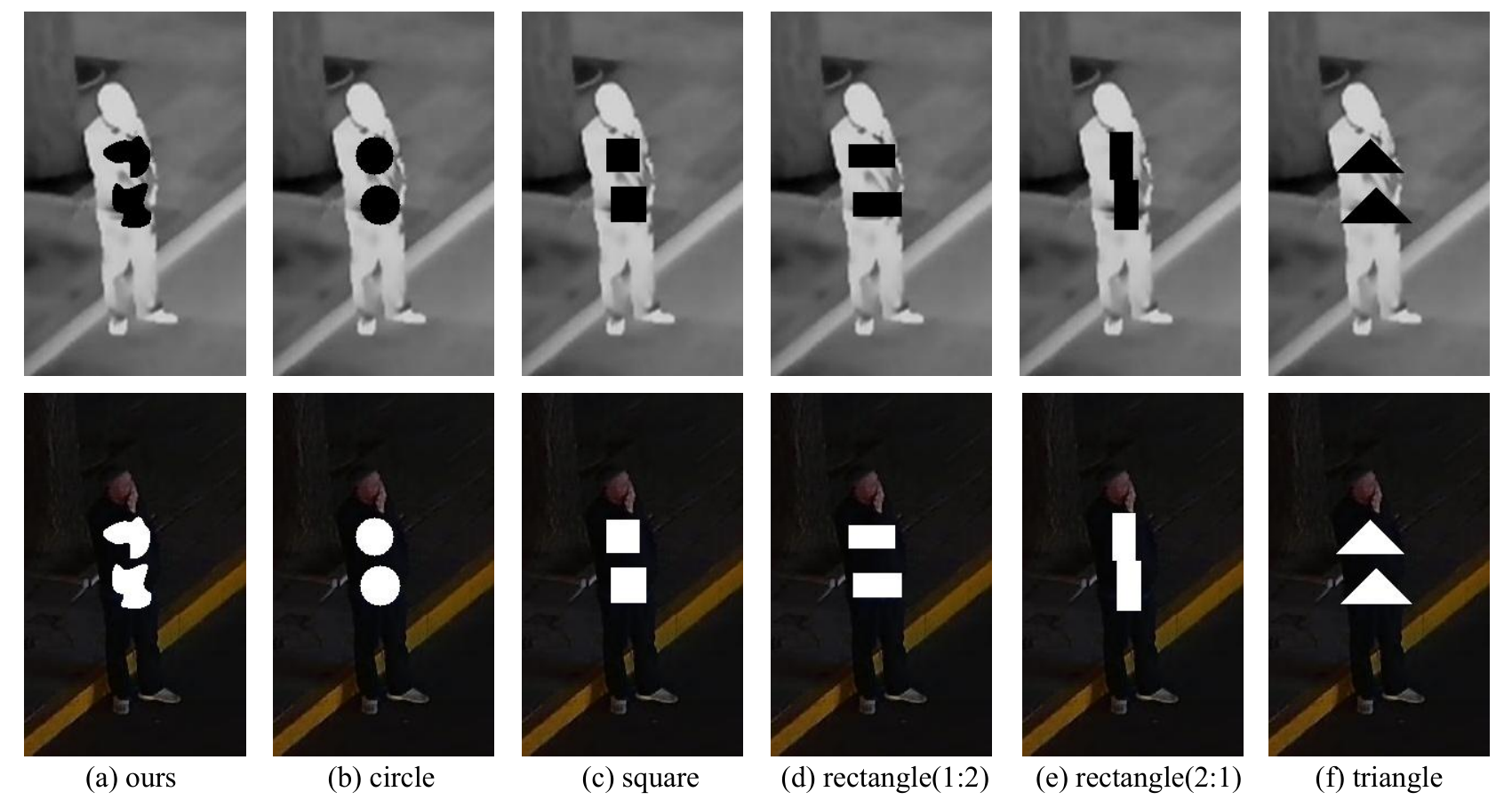
Here, we provide the ablation study to investigate the outcomes of our optimized shapes. Specifically, we first generate cross-modal adversarial patches to achieve the optimal shapes for a given pedestrian. Some examples of the optimal shapes in the digital world are shown in Figure 10. Then, we fix the patches’ locations and sizes while changing their shapes into basic shapes. These basic shapes can be circles, squares, rectangles and triangles, which are presented at Figure 11. Then we compute the ASR and AP drop under these five shapes. This setting verifies the effectiveness of our optimal shapes on the attacks. The results are listed in Table II, where we see that compared with our optimal shapes, basic shapes barely work with an average ASR of 5.23%, an average AP drop of 20.73% in the visible modality and 11.65% in the infrared modality.
| Shape | ASR | AP drop(Visible) | AP drop(Infrared) |
|---|---|---|---|
| Circle | 15.00% | 26.83% | 42.28% |
| Square | 2.50% | 22.76% | 4.07% |
| Rectangle(1:2) | 0.00% | 17.07% | 0.81% |
| Rectangle(2:1) | 3.33% | 31.71% | 8.94% |
| Triangle | 5.83% | 26.02% | 13.82% |
| Average | 5.23% | 20.73% | 11.65% |
| Ours | 73.33% | 99.19% | 74.31% |
IV-A3 Effects of Score-aware Iterative Evaluation
To verify the impact of the Cross-modal Fitness Function, we design a set of comparative experiments. As mentioned in Section III-C3, our method can combine the visible modality and infrared modality into a whole, which helps balance attack performances between different modalities. Here, we use a direct sum of Eq.(14) and Eq.(15) instead of Eq.(13) as the not-combined fitness function.
| Fitness Function | Ours | Direct Sum |
|---|---|---|
| ASR | 73.33% | 50.83% |
| AP drop (Visible) | 99.19% | 85.37% |
| AP drop (Infrared) | 74.31% | 66.99% |
From Table III, we can find that although a direct sum fitness function can have an AP decrease of 85.37% in the visible modality and 66.99% in the infrared modality, it suffers an obvious decline in ASR under a cross-modal standard.
Then, to further demonstrate the effectiveness of our method, we visualize their specific optimization processes. As shown in Figure 12, with and representing the current progress towards the success of attack in the corresponding modality (Eq.(14)-Eq.(15) in the paper, the larger, the closer to success), our method balances the differences between two modalities and achieves simultaneous progress for both, whereas a simple sum tends to focus on a single easy-to-attack modality, such as the infrared modality in Figure 12 (b).

IV-A4 Effects of Integrating with Position
As position may also be an important attribute to the attack performance, we conduct a comparison experiment to quantify the effect of combining the shape with the position. The results listed in Table IV show that, the ASR of joint optimization of shape and position has reached 83.33% with an increase of 10%, which confirms the necessity to consider the position attribute.
| Optimization attributes | Shape | Shape + Position |
|---|---|---|
| ASR | 73.33% | 83.33% |
| AP drop (Visible) | 99.19% | 94.31% |
| AP drop (Infrared) | 74.31% | 88.30% |
IV-A5 Compared with Other Shape Optimization Methods

Wei et al.[13] propose a shape optimization of utilizing nine-square-grid shapes to attack infrared detectors (called as hotcold block). Since their method is also a black-box attack, we can easily combine Wei et al.[13]’s shape modeling manner with our score-aware iterative function to conduct the comparison. We ensure to use the same patch number and patch size for these two methods. From Table V, we can see that the hotcold block only has an ASR of 30.83%, which supports our belief that the search space of such nine-square-grid shapes is greatly limited. Moreover, as Figure 13 (b) shows, some hotcold block’s optimized positions may not be possible for patches to fix at, causing the difficulty and instability of physical implementation.
We also compare our method with deformable shape [18].We give a visualization comparison for the optimized shapes between [18] and ours in Figure 13 , where we can see that the deformable patches are heteromorphic as shown in Figure 13 (c), not easy to implement accompanied by potentially greater implementation errors in the physical world. In contrast, our shape in Figure 13 (a) is more natural, and thus is easy-to-implement to attach on the pedestrian to achieve an effective physical attack. Besides, [18] aims to attack image classifiers in the visible domain, while ours aims to attack object detectors in both the visible and infrared domains, which is another difference between the two methods.

Moreover, we utilize the latest shape optimization method in Wei et al.[14] and adapt their attack loss into the two-modality form like our fitness evaluation to perform a comparison. As Figure 13 (d) shows, despite its competitive naturalness with [13] and [35], it still has slight sawtooth on the edge. As for the quantitative attack performance of the above methods, Table V significantly shows our method’s best performance among the four, achieving an ASR of 83.33%, an AP drop of 94.31% in the visible modality and 88.30% in the infrared modality, while the other three have poorer attack performances obviously.
| Detectors | YOLOv3 | YOLOv5 | YOLOv7 | Faster RCNN | EfficientDet | RetinaNet |
|---|---|---|---|---|---|---|
| ASR | 83.33% | 71.67% | 80.00% | 69.17% | 67.50% | 68.33% |
| AP drop (Visible) | 94.31% | 82.11% | 89.66% | 89.38% | 76.48% | 82.11% |
| AP drop (Infrared) | 88.30% | 87.18% | 93.84% | 83.94% | 84.77% | 71.06% |
IV-A6 Attack Performances against Various Object Detectors
Considering the differences between detection systems, we first verify our method in six typical and mainstream detectors: YOLOv3, YOLOv5, YOLOv7, Faster RCNN, EfficientDet and RetinaNet. We use ASR and AP drop to evaluate the attack performance. The results are shown in Table VI.
From the above results, we can see that our method is equally useful despite the distinctions between the one-stage and two-stage detection models. For the typical one-stage detection models of the YOLO series, we first achieve an ASR of 83.33%, an AP drop of 94.31% in the visible modality and 88.30% in the infrared modality for the classic model YOLOv3, then for the upgraded detectors YOLOv5 and YOLOv7, we still achieve good performances. In the meantime, for the two-stage detection model Faster RCNN, we achieve an ASR of 69.17%, an AP drop of 89.38% in the visible modality and 83.94% in the infrared modality. As for EfficientDet and RetinaNet, our method can achieve similar results to Faster RCNN on these high-performance detectors, which confirms our method’s generality across different detection systems.

Then, we also try to test our attack against the latest CLIP-based detectors, like VL-PLM[42]. For the target modality, due to CLIP-based detectors’ custom usage in the visible modality, we follow it and select the visible light domain. For the attack method, because our method is a score-based black-box attack, faced with the single modality, we can also use the confidence scores to perform single-modality attacks. The corresponding ASR is 75.83%, which shows that the current visual-language models are also vulnerable to our method. Figure 15 shows the visualized attack effects on VL-PLM. Compared the two examples, we can observe that with our adversarial patches, this model with high-precision target detection (and even segmentation) capabilities has also lost its powerful function.
IV-A7 Robustness to Implementation Errors
Since the patch is in general generated digitally by considering the optimal shape and fixed location, when it is applied to real scenarios, it is natural to see how sensitive it would be to the attack success rate if we do not cut and paste the patch in 100% exact shape and location on the clothes. Therefore, we simulate possible position shifts and clipping errors when conducting physical experiments. Table VII demonstrates our cross-modal patches’ robustness to translation errors and incompleteness.
| Translation | Incompleteness | |||||||||||
| 3pix | 5pix | 5% | 10% | |||||||||
| ASR |
|
|
|
| ||||||||

IV-B Attacks in the physical world
IV-B1 Physical Attacks against Pedestrian Detector
To verify the effectiveness of unified adversarial patches in various physical settings, we design numerous scenarios for conducting physical attacks and capture videos to compute the ASR. By default, we make recordings of interior scenes at a distance of 4 meters from a standing person in the frontal view (). For each situation, we shoot for 20 seconds at ten frames per second (about 200 frames in total) and compute the ASR versus the captured video. The pedestrian detection threshold is set at 0.7 according to [5].
For the angle problem, we change the angles with , . For distance, we move the camera to 6 meters from the default 4 meters. For posture, we change the pedestrian’s posture from the default standing pose to the sitting pose. As for the scene, we change to outdoor from the default indoor. The visual examples of these situations are listed in Figure 14. During the shooting process, the pedestrian is asked to move the body within the range of of the current posture to take videos. Table VIII lists the quantitative results. It can be seen that our infrared patches achieve a high ASR (73.50%) in the frontal view. When the shooting angle changes, the ASR still maintains a high value (67.00% and 46.50%). When changing the distance from 4 meters to 6 meters, the ASR decreases to 71.00%. When changing the posture from standing to sitting, the ASR decreases to 61.50%, and ASR decreases to 57.00% when the scene is changed to outdoor. These results show that the impact of different shooting situations is relatively small to the cross-modal patches. In other words, as long as the shape of our cross-modal patch on the object can be generally captured by the camera, the effects of adversarial attacks can be maintained.
| Setting | dist. | pos. | outdoor | |||
|---|---|---|---|---|---|---|
| ASR | 73.50% | 67.00% | 46.50% | 71.00% | 61.50% | 57.00% |
IV-B2 Affine-Transformation-based Enhancement Strategy
Considering that pedestrians always have different angular deflections under object detectors when moving, we aim to generate more robust shapes that can be fully detected at multiple angles with a stronger adversarial effect. Specifically, we use the multi-angle joint optimization method proposed in Section III-D1 to obtain the optimal patches’ shapes that are more applicable for multi-angle situations, and the visualization results of the attack performances compared with the clean target is shown in Figure 16. Then, we contrast the enhanced version with the normal version and the quantitative results are also given in Figure 16, where we can see that with the proposed enhancement strategy, the attack success rate has generally increased by a significant average ASR of 30%. Besides, compared with Figure 14, we can intuitively observe that patch generation that takes angle factor into account may tend to learn a bilateral distribution as shown in Figure 16 rather than a relatively centralized one. This could be interpreted by the fact that patches located in the middle area of the object may be detected as a narrow strip at a large deflection angle, which will lose attack performance in the physical world.
IV-B3 Physical Attacks against Vehicle Detector

Besides the pedestrian detection task, our unified adversarial patch can also be applied to other tasks. In this section, we conduct the experiments of physical attacks against vehicle detection based on YOLOv3. Like the pedestrian detection task, we record the vehicle video (200 frames per distance) captured at different distances (1m, 2m, 3m, 4m, 5m) and different angles(-30∘, -15∘, 0∘, +15∘, +30∘), and then compute the ratio of successfully attacked video frames out of all the frames as the ASR.
The specific results are given in Figure 17, where the left denotes the qualitative examples and the right denotes the quantitative ASR against different distances and angles. To give a clear comparison, we list two vehicle images of the same modality in one row, where the vehicle attached by the unified adversarial patch cannot be detected but the clean vehicle is successfully detected. Additionally, we see the patch’ size is small versus the vehicle, but it indeed performs successful adversarial attacks, which proves the vulnerability of vehicle detector against the unified adversarial patch. The right quantitative results show the high attack performance versus different distances (96.50% at 1m, 93.50% at 2m, 94.50% at 3m, 91.50% at 4m, 83.50% at 5m) and different angles (81.5% at -30∘, 86.50% at -15∘, 93.50% at 0∘, 85.00% at +15∘, 80.50% at +30∘). It shows the similar trends with the pedestrian detection task.
IV-C Defenses against Unified Adversarial Patches
| Defense Methods | ASR | Error |
|---|---|---|
| No Defense | 73.33% | 0.00% |
| Spatial Smoothing [43] | 64.17% | 9.16% |
| Adversarial Training [23] | 50.00% | 23.33% |
We test two typical methods to defend our attack method in the digital world. One is pre-processing defense: spatial smoothing [3], and another is adversarial training [23]. The defense results are given in Table IX, where we see that: (1) After spatial smoothing, the ASR only drops 9.16%. This is reasonable because the cover image in our method has the same value, the smooth operation cannot change the distribution. (2) After adversarial training, the ASR drops 23.33%, which is still acceptable. It shows the robustness of our unified adversarial patches.
V Conclusion
In this paper, we proposed a unified adversarial patch in the physical world. For that, we uncovered the property that could react both in the visible and infrared modalities: shape. Then, combining the boundary-limited shape optimization with the score-aware iterative fitness evaluation, we guaranteed an efficient exploration of the adversarial shape and the balance between different modalities. We also proposed an Affine-Transformation-based enhancement strategy to cope with the shape deformation caused by different shooting angles in the real world. Experiments on the pedestrian detection and vehicle detection tasks in the digital world and physical world verified the effectiveness of our proposed method. In the future, we will apply our method on more visual tasks to demonstrate its good generalization.
References
- [1] C. Szegedy, W. Zaremba, I. Sutskever, J. Bruna, D. Erhan, I. Goodfellow, and R. Fergus, “Intriguing properties of neural networks,” arXiv preprint arXiv:1312.6199, 2013.
- [2] X. Wei, B. Pu, J. Lu, and B. Wu, “Visually adversarial attacks and defenses in the physical world: A survey,” arXiv:2211.01671, 2023.
- [3] K. Xu, G. Zhang, S. Liu, Q. Fan, M. Sun, H. Chen, P.-Y. Chen, Y. Wang, and X. Lin, “Adversarial t-shirt! evading person detectors in a physical world,” in Computer Vision–ECCV 2020: 16th European Conference, Glasgow, UK, August 23–28, 2020, Proceedings, Part V 16. Springer, 2020, pp. 665–681.
- [4] X. Zhu, X. Li, J. Li, Z. Wang, and X. Hu, “Fooling thermal infrared pedestrian detectors in real world using small bulbs,” in Proceedings of the AAAI Conference on Artificial Intelligence, vol. 35, no. 4, 2021, pp. 3616–3624.
- [5] X. Zhu, Z. Hu, S. Huang, J. Li, and X. Hu, “Infrared invisible clothing: Hiding from infrared detectors at multiple angles in real world,” in Proceedings of the IEEE/CVF Conference on Computer Vision and Pattern Recognition, 2022, pp. 13 317–13 326.
- [6] M. Yuan and X. Wei, “C2former: Calibrated and complementary transformer for rgb-infrared object detection,” arXiv preprint:2306.16175, 2023.
- [7] X. Wei, Z. Tao, C. Zhang, and X. Cao, “Structured saliency fusion based on dempster–shafer theory,” IEEE Signal Processing Letters, vol. 22, no. 9, pp. 1345–1349, 2015.
- [8] S. Liang, B. Wu, Y. Fan, X. Wei, and X. Cao, “Parallel rectangle flip attack: A query-based black-box attack against object detection,” in 2021 IEEE/CVF International Conference on Computer Vision (ICCV). IEEE, 2021, pp. 7677–7687.
- [9] Y. Dong, S. Ruan, H. Su, C. Kang, X. Wei, and J. Zhu, “Viewfool: Evaluating the robustness of visual recognition to adversarial viewpoints,” in Advances in Neural Information Processing Systems (NeurIPS), 2023.
- [10] S. Thys, W. Van Ranst, and T. Goedemé, “Fooling automated surveillance cameras: adversarial patches to attack person detection,” in Proceedings of the IEEE/CVF conference on computer vision and pattern recognition workshops, 2019, pp. 0–0.
- [11] X. Wei, Y. Guo, J. Yu, and B. Zhang, “Simultaneously optimizing perturbations and positions for black-box adversarial patch attacks,” IEEE Transactions on Pattern Analysis and Machine Intelligence, 2022.
- [12] Y. Dong, C. Kang, J. Zhang, Z. Zhu, Y. Wang, X. Yang, H. Su, X. Wei, and J. Zhu, “Benchmarking robustness of 3d object detection to common corruptions,” in Proceedings of the IEEE/CVF Conference on Computer Vision and Pattern Recognition, 2023, pp. 1022–1032.
- [13] H. Wei, Z. Wang, X. Jia, Y. Zheng, H. Tang, S. Satoh, and Z. Wang, “Hotcold block: Fooling thermal infrared detectors with a novel wearable design,” AAAI, 2023.
- [14] X. Wei, J. Yu, and Y. Huang, “Physically adversarial infrared patches with learnable shapes and locations,” in IEEE Conference on Computer Vision and Pattern Recognition, 2023, pp. 12 334–12 342.
- [15] M. Abdelfattah, K. Yuan, Z. J. Wang, and R. Ward, “Adversarial attacks on camera-lidar models for 3d car detection,” in 2021 IEEE/RSJ International Conference on Intelligent Robots and Systems, 2021, pp. 2189–2194.
- [16] J. Tu, H. Li, X. Yan, M. Ren, Y. Chen, M. Liang, E. Bitar, E. Yumer, and R. Urtasun, “Exploring adversarial robustness of multi-sensor perception systems in self driving,” arXiv preprint arXiv:2101.06784, 2021.
- [17] S. Wang, T. Wu, A. Chakrabarti, and Y. Vorobeychik, “Adversarial robustness of deep sensor fusion models,” in IEEE Winter Conference on Applications of Computer Vision, 2022, pp. 2387–2396.
- [18] Z. Chen, B. Li, S. Wu, J. Xu, S. Ding, and W. Zhang, “Shape matters: deformable patch attack,” in European Conference on Computer Vision. Springer, 2022, pp. 529–548.
- [19] T. B. Brown, D. Mané, A. Roy, M. Abadi, and J. Gilmer, “Adversarial patch,” arXiv preprint arXiv:1712.09665, 2017.
- [20] C. Szegedy, W. Zaremba, I. Sutskever, J. Bruna, D. Erhan, I. Goodfellow, and R. Fergus, “Intriguing properties of neural networks,” in 2nd International Conference on Learning Representations, ICLR 2014, 2014.
- [21] N. Carlini and D. Wagner, “Towards evaluating the robustness of neural networks,” in 2017 ieee symposium on security and privacy (sp). Ieee, 2017, pp. 39–57.
- [22] S.-M. Moosavi-Dezfooli, A. Fawzi, and P. Frossard, “Deepfool: a simple and accurate method to fool deep neural networks,” in Proceedings of the IEEE conference on computer vision and pattern recognition, 2016, pp. 2574–2582.
- [23] I. J. Goodfellow, J. Shlens, and C. Szegedy, “Explaining and harnessing adversarial examples,” arXiv preprint arXiv:1412.6572, 2014.
- [24] A. Kurakin, I. Goodfellow, and S. Bengio, “Adversarial machine learning at scale,” arXiv preprint arXiv:1611.01236, 2016.
- [25] A. Madry, A. Makelov, L. Schmidt, D. Tsipras, and A. Vladu, “Towards deep learning models resistant to adversarial attacks,” arXiv preprint arXiv:1706.06083, 2017.
- [26] M. Sharif, S. Bhagavatula, L. Bauer, and M. K. Reiter, “Accessorize to a crime: Real and stealthy attacks on state-of-the-art face recognition,” in Proceedings of the 2016 acm sigsac conference on computer and communications security, 2016, pp. 1528–1540.
- [27] S. Komkov and A. Petiushko, “Advhat: Real-world adversarial attack on arcface face id system,” in 2020 25th International Conference on Pattern Recognition (ICPR). IEEE, 2021, pp. 819–826.
- [28] X. Wei, Y. Guo, and J. Yu, “Adversarial sticker: A stealthy attack method in the physical world,” IEEE Transactions on Pattern Analysis and Machine Intelligence, 2022.
- [29] X. Wei, Y. Huang, Y. Sun, and J. Yu, “Unified adversarial patch for cross-modal attacks in the physcial world,” in International Conference on Computer Vision, ICCV 2023, 2023.
- [30] K. Eykholt, I. Evtimov, E. Fernandes, B. Li, A. Rahmati, C. Xiao, A. Prakash, T. Kohno, and D. Song, “Robust physical-world attacks on deep learning visual classification,” in Proceedings of the IEEE conference on computer vision and pattern recognition, 2018, pp. 1625–1634.
- [31] T. B. Brown, D. Mané, A. Roy, M. Abadi, and J. Gilmer, “Adversarial patch,” arXiv preprint arXiv:1712.09665, 2017.
- [32] C. Twigg, “Catmull-rom splines,” Computer, vol. 41, no. 6, pp. 4–6, 2003.
- [33] K. Price, R. M. Storn, and J. A. Lampinen, Differential evolution: a practical approach to global optimization, 2006.
- [34] V. Bazarevsky and I. Grishchenko, “On-device, real-time body pose tracking with mediapipe blazepose,” Google AI Blog, 2020.
- [35] M. A. Fischler and R. C. Bolles, “Random sample consensus: a paradigm for model fitting with applications to image analysis and automated cartography,” Communications of the ACM, vol. 24, pp. 381–395, 1981.
- [36] X. Jia, C. Zhu, M. Li, W. Tang, and W. Zhou, “Llvip: A visible-infrared paired dataset for low-light vision,” in Proceedings of the IEEE/CVF International Conference on Computer Vision, 2021, pp. 3496–3504.
- [37] J. Redmon and A. Farhadi, “Yolov3: An incremental improvement,” arXiv preprint arXiv:1804.02767, 2018.
- [38] C.-Y. Wang, A. Bochkovskiy, and H.-Y. M. Liao, “Yolov7: Trainable bag-of-freebies sets new state-of-the-art for real-time object detectors,” arXiv preprint arXiv:2207.02696, 2022.
- [39] S. Ren, K. He, R. Girshick, and J. Sun, “Faster r-cnn: Towards real-time object detection with region proposal networks,” Advances in neural information processing systems, vol. 28, 2015.
- [40] M. Tan, R. Pang, and Q. V. Le, “Efficientdet: Scalable and efficient object detection,” in Proceedings of the IEEE/CVF conference on computer vision and pattern recognition, 2020, pp. 10 781–10 790.
- [41] T.-Y. Lin, P. Goyal, R. Girshick, K. He, and P. Dollár, “Focal loss for dense object detection,” in Proceedings of the IEEE international conference on computer vision, 2017, pp. 2980–2988.
- [42] S. Zhao, Z. Zhang, S. Schulter, L. Zhao, B. Vijay Kumar, A. Stathopoulos, M. Chandraker, and D. N. Metaxas, “Exploiting unlabeled data with vision and language models for object detection,” in ECCV, 2022, pp. 159–175.
- [43] W. Xu, D. Evans, and Y. Qi, “Feature squeezing: Detecting adversarial examples in deep neural networks,” arXiv preprint:1704.01155, 2017.
