Multiplication of the orbital angular momentum of phonon polaritons via sublinear dispersion
Abstract
Optical vortices (OVs) promise to greatly enhance optical information capacity via orbital angular momentum (OAM) multiplexing. The need for on-chip integration of OAM technologies has prompted research into subwavelength-confined polaritonic OVs. However, the topological order imprinted by the structure used for the transduction from free-space beams to surface polaritons is inherently fixed after fabrication. Here, we overcome this limitation via dispersion-driven topological charge multiplication. We switch the OV topological charge within a small frequency range by leveraging the strong sublinear dispersion of low-loss surface phonon polaritons (SPhP) on silicon carbide membranes. Applying the Huygens principle we quantitatively evaluate the topological order of the experimental OVs detected by near-field imaging. We further explore the deuterogenic effect, which predicts the coexistence of multiple topological charges in higher-order polaritonic OVs. Our work demonstrates a viable method to manipulate the topological charge of polaritonic OVs, paving the way for the exploration of novel OAM-enabled light-matter interactions at mid-infrared frequencies.
1 Introduction
Vortices with defined topological features are an ubiquitous phenomenon in physics, appearing in different systems including superconductors Abrikosov 1957, superfluids Lounasmaa and Thuneberg 1999, exciton polaritons Lagoudakis et al. 2008; Lerario et al. 2017 and magnetic materials Lin et al. 2014; Chmiel et al. 2018. Recently, propagating vortex beams characterized by twisted helical wavefronts carrying intrinsic orbital angular momentum (OAM) have been realized with electrons Uchida and Tonomura 2010; Verbeeck et al. 2010, neutrons Clark et al. 2015; Sarenac et al. 2022 and helium atoms Luski et al. 2021, providing a new emerging tool for the investigation of fundamental particles and interactions Ivanov 2022. Optical vortices (OVs), the photon counterpart of such beams, constitute a theoretically unbounded set of orthogonal OAM modes, promising enhanced optical Wang et al. 2012; Yan et al. 2014; Willner et al. 2015 and quantum Mair et al. 2001; Nagali et al. 2009; Fickler et al. 2014 information processing via OAM multiplexing. Pioneered by Allen Allen et al. 1992, OVs are most usually generated by spiral phase plates Yan et al. 2014, spatial light modulators (SLM) Wang et al. 2012, and more recently with metasurfaces Pu et al. 2015; Devlin et al. 2017; Dorrah et al. 2021; Ren and Maier 2022; de Oliveira et al. 2022; Ahmed et al. 2022. Regardless of the method, the minimum size of free-space OVs is fundamentally limited by the diffraction limit of light, while reduction of the OVs footprint is required for on-chip integration Genevet et al. 2012; Ren et al. 2016; Yue et al. 2018; Ji et al. 2020; Ren et al. 2021 and unveiling of new light-matter interaction regimes Machado et al. 2018; Konzelmann et al. 2019; Ni et al. 2021.
A route for realizing subwavelength OVs is via coupling optical beams into highly confined surface states such as surface plasmon polaritons (SPPs) Maier 2007; Kim et al. 2010; David et al. 2015; David et al. 2016; Spektor et al. 2017; Yang et al. 2020; Spektor et al. 2021; Frischwasser et al. 2021; Bai et al. 2022; Prinz et al. 2023 and surface phonon polaritons (SPhPs) Caldwell et al. 2015; Xiong et al. 2021; Wang et al. 2022 through spin-orbit interactions Bliokh et al. 2015. However, the topological charge offered by the surface structure used for launching polaritonic OVs is always a fixed quantity after device fabrication. The imprinted topological charge due to propagation phase-delay is proportional to the polariton momentum , and can be then varied by multiplication of the wavevector by an integer factor (see Supplementary Note ).
The required frequency variation to achieve a certain momentum shift is governed by the dispersion, a general property of waves governing the propagation and light-matter interactions of electromagnetic fields. As the dispersion of light in free-space is linear, doubling the momentum requires a frequency increase, making this approach impractical for most applications (Fig. 1a, blue line). In contrast, the required frequency variation for polaritonic OVs is significantly reduced due to their deeply sublinear dispersion (Fig. 1a, red curve). This small frequency change opens the possibility of flexible manipulation of the topological charge of polaritonic OVs. Even though the SPPs dispersion departs from the linear behavior, this occurs only in the region of high material losses Maier 2007; Khurgin 2015. SPhPs are characterized by low losses even in the deeply sublinear dispersion regime due to the reduced phonon-phonon scattering rate Caldwell et al. 2015. As such, SPhPs vortices have recently been realized in a hexagonal boron nitride film on gold Wang et al. 2022, however the measured OVs near-field profiles were distorted due to tilted illumination, obscuring a clear evaluation of the topological order.
Here we demonstrate dispersion-driven OAM multiplication in highly confined SPhP vortices based on suspended thick silicon carbide (SiC) membranes Mancini et al. 2022. We realize the multiplication of polaritonic topological orders based on different surface structures with only a small variation in the excitation frequency (Fig. 1b). By introducing a set of reference functions accounting for material losses, we quantitatively determine the topological order of the experimental SPhP vortices mapped via a normal-incidence transmission-type near-field microscope (Fig. 1c). We precisely track the evolution of the SPhP OVs with high mode purity through a small frequency tuning. Furthermore, we investigate the deuterogenic effect predicting the coexistence of multiple OAM modes in surface structures producing higher order polaritonic OVs Yang et al. 2020. As a result, our demonstration presents a viable approach to flexible manipulation of the topological charge of polaritonic OVs, paving the way for the exploration of novel OAM-enabled light-matter interactions at the subwavelength scale.
2 Results

In polar thin films, hybridization between the individual SPhPs supported by the top and bottom interfaces occurs when the film thickness becomes comparable to the material skin depth Mancini et al. 2022. In this regime splitting of the SPhP dispersion is observed, with the two modes characterized by symmetric and anti-symmetric out-of plane electric field distributions Dionne et al. 2005. In this paper we focus on the anti-symmetric mode as it features lower losses and longer propagation lengths (see Supplementary Note ). The dispersion relation for the anti-symmetric mode of a SiC membrane calculated through the transfer-matrix approach Passler and Paarmann 2017 is shown in Fig. 1d.
We show the dispersion-driven multiplication of a SPhP OV topological order by simulating its out-of plane electric field component through the Huygens principle Teperik et al. 2009; Tsesses et al. 2019 (see Supplementary Note ). Multiple point sources are arranged in the shape of a vortex generator (VG) (see Supplementary Note ) defined by the SPhP wavelength , the topological order and its minimum radius . A VG with and designed at (where the predicted SPhP wavelength is ) is used for the simulations shown in Fig. 1d. Only the phase of the calculated electric field is shown. We use the convention that anti-clockwise rotation is associated with a , while clockwise rotation with a sign. The SPhP phase profile under circularly polarized excitation is shown in Fig. 1d at , and where the SPhP wavelength is and , corresponding to a multiplication of by a factor of and . The total OAM of the polaritonic OV at the design wavelength is given by , where and are the OAM and spin states of the incident beam. In the rest of the paper we only consider cases where the exciting beam carries no OAM, so that . The SPhP vortex OAM is , and , as the geometrical phase delay imprinted by the VG changes from at to at .
To quantitatively assess the purity of the obtained polaritonic OVs, an overlap integral between the simulated or experimental data with a set of reference functions is commonly used Yang et al. 2020; de Oliveira et al. 2022. While for free-space OAM beams Laguerre-Gaussian (LG) modes are employed as reference, these are not suited to represent the characteristic spiral phase pattern appearing in polaritonic OVs, which is a result of material losses. We calculate from an integral approach the of a SPhP vortex at various , constituting a set of suitable basis functions (see Supplementary Note ). The overlap integral can be computed as a function of both the topological order and of the frequency (see Supplementary Note ). In Fig. 1e-g the overlap spectra for the simulated maps reported in Fig. 1d are shown. The spectrum in Fig. 1g shows the high purity of the simulated vortex. The purity decreases in Fig.1f, e, but the spectra clearly peak at and , as expected. The overlap integral evaluated at fixed as a function of frequency is shown in Fig.1h-j. A clear peak can be observed for at , for at and for at . Intriguingly, these plots demonstrate that from theoretical simulations a single fixed VG can lead to the creation of vortices with different topological orders. By leveraging the strong sublinear SPhP dispersion, a slight tuning of the incident frequency is sufficient to multiply the polaritonic vortex order.
To experimentally demonstrate the creation of SPhP vortexes, we map the near-field pattern of the polaritonic OVs by employing a transmission scattering-scanning near-field optical microscope (sSNOM) as sketched in Fig. 1c. Transmission sSNOM has the advantage of normal incidence excitation and reduced tip-sample interaction, and has been the method of choice to investigate complex SPP patterns David et al. 2015; David et al. 2016; Tsesses et al. 2018; Tsesses et al. 2019 and resonating plasmonic nanoantennas Schnell et al. 2009; Schnell et al. 2010; Alonso-Gonzalez et al. 2011; Bohn et al. 2015. We avoid using reflection sSNOM, where light is focused on the tip at a tilted angle, as this inevitably distorts the OVs pattern for multiple reasons. First, the VG design assumes excitation with a normal-incident plane wave; and second, the edge-launched SPhP fringes periodicity in reflection sSNOM depends on the relative angle between the incident beam k-vector and the edge in-plane normal direction Kaltenecker et al. 2020; Sternbach et al. 2020; Mancini et al. 2022; Luan et al. 2022, which varies along the VG geometry. In the experiments, right (RCP) or left (LCP) circularly polarized light impinges from below the sample at normal incidence. SPhP are launched by a thin Chromium (Cr) VG fabricated by standard electron beam lithography on a SiC membrane. The near-field from the OVs is scattered by a metallic AFM tip, which oscillates at for background suppression obtained by demodulation of the signal at with . The width of the VG arms is chosen to be , which we confirm is appropriate for efficient SPhP launching (see Supplementary Note ).
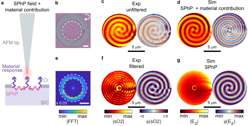
As sketched in Fig.2a, the sSNOM signal is composed by the interference between the SPhP field and the bare response of the material, also called material contrast Tamagnone et al. 2018. As a consequence, the raw sSNOM signal is qualitatively different from the expected SPhP OV profile. In Fig. 2b we report a SEM image of a VG with and , designed at and fabricated on top of a SiC membrane. The VG is excited with LCP light at the design frequency, and the measurements are shown for the circular region indicated by the white dashed line. Experimental amplitude and phase maps demodulated at are shown in Fig. 2c. The data are clipped and corrected as detailed in Supplementary Note . The resulting vortex is deeply subwavelength as at this frequency. We demonstrate a maximum SPhP vortex confinement of at , corresponding to as reported in Supplementary Note . The spiral pattern in the vortex amplitude can be attributed to the interference with the material background. At the same time the phase jumps along the SPhP propagation direction are expected to go from to , while we measure smaller oscillations. To reproduce the experimental maps, it is sufficient to add a constant complex material background to the simulated SPhP field. By choosing appropriate values of and , we obtain good agreement with the experimental maps as shown in Fig. 2d. The position-independent material contribution can be removed by filtering the 2-dimensional fast fourier transform (FFT) of the experimental data as shown in Fig. 2e. Only a region around the value of the predicted is retained by multiplication with a mask that is outside the region highlighted by the white dashed lines in Fig. 2e, and inside. In Fig. 2e the region to be masked is multiplied by to show the dominant central peak associated with the material contrast. By inverse FFT, the bare SPhP contribution can be retrieved as shown in Fig. 2f. The corresponding simulated SPhP field is shown in Fig. 2g, demonstrating good agreement with the retrieved experimental maps. We evaluate the purity of the filtered experimental data in Fig. 2f to be (see Supplementary Note ), demonstrating the high accuracy of the generated and measured SPhP OV, allowing a clear evaluation the topological charge.

To experimentally confirm the dispersion-driven OAM multiplication, we quantitatively assess the topological order of a SPhP vortex when changing the excitation frequency. In Fig. 3a, we report the simulated integral overlap for a VG designed at with and excited by RCP light. We show the obtained spectra for and with purple and orange curves, respectively. A peak at the design frequency for can be seen in Fig. 3a labeled as (i). The spectrum for instead shows a peak at indicated by (v), where and is the SPhP wavelength at the design frequency. In Fig. 3b we report a false-color SEM image of the fabricated VG. We carry out experiments at five different frequencies, , , , and , labeled from (i) to (v) in Fig. 3. For each wavelength we report in Fig. 3c the FFT filtered phase map along with the experimental overlap integral. We indicate with purple bars the contribution at and with orange bars the one at . The simulated values of the overlap integrals at the measured frequencies are highlighted by purple and orange arrows for and , respectively. The experimental data are in excellent agreement with the simulations, as we can track the gradual change from to while also quantifying intermediate states given by a superposition of both vortex modes.

In Fig. 3 we demonstrated experimentally the OAM multiplication for . We explore by simulations the same phenomena for different VGs excited by LCP light with and in Fig. 4. We report the data as a table, where the rows indicate the different investigated VGs. In of Fig. 4a we show sketches of the VGs. In Fig. 4b, c and d we report the simulated amplitude and phase maps at frequencies , and , at which the SPhP momentum is doubled and tripled with respect to the one at . For each VG we calculate the overlap integral as a function of both frequency and topological order as shown in of Fig. 4e. The overlap integral peaks for all VGs at the three frequencies and . The OAM multiplication operation can be observed by noticing that in Fig. 4e adjacent maxima in are spaced exactly by . Therefore, the OAM multiplication can be applied in principle for any value of .

In Fig. 4 we showed that very high OAM orders can be obtained through the multiplication procedure, as for the case we obtain a maximum order of for . We demonstrate that we can create and effectively measure these high order OVs. In particular we look into the coexistence of multiple OAM orders in polariton OVs, which has been recently shown to occur for SPPs Yang et al. 2020. This phenomena has been referred to as the ”deuterogenic effect” to indicate the presence of secondary OVs as a consequence of the VG geometry used for the vortices creation. According to this principle, the total OAM order of a polariton OV is given by Yang et al. 2020:
| (1) |
with and and the OAM and spin states of the excitation beam. In Fig. 5a-c we report amplitude and phase near-field maps for vortices of order , and respectively. The measurements are performed at with RCP excitation. As the footprint of higher order vortices is larger, we use here for the definition of the VGs. In Fig. 5d-f we report filtered amplitude and phase maps, together with the corresponding simulations shown in Fig. 5g-i. We calculate the associated overlap integrals as displayed in Fig. 5j-l together with false-color SEM images of the Cr ridges used for SPhP launching. We observe that for higher the mode purity decreases. In Fig. 5j, k we detect the coexistence of modes and with the order, as predicted from eq. (1) for and . The modes associated with the deuterogenic effect are indicated by gray bars. For the vortex we can also observe a strong peak at order , which is again expected from eq. (1) for , and . While the deuterogenic effect for has been observed for SPP Yang et al. 2020, we report here the first experimental detection of a contribution, indicating that further terms in eq. (1) have to be considered to properly describe the generated polaritonic OV.
Intuitively, the generation of the central vortex can be associated with the SPhP launched by the corners of the VG arms, which overall constitute a circle of emitting dipoles. In this case there is no additional phase delay from the structure, and the vortex is equal to the sum of the SAM and OAM of the incident beam. This effect can be attenuated by reducing the number of arms of the VG and increasing the phase delay imprinted by each section of the VG (see Supplementary Note ). A balance between attenuation of the central lobe and the azimuthal distortion due to propagation losses has to be found depending on the application.
3 Discussion
We leverage the strong sublinear SPhP dispersion to obtain vortices with multiplied topological orders by a small increase of the incident frequency of around . This value can be further reduced by operating at higher frequencies where the group velocity is smaller. In comparison, an approximately increase in the operation frequency for free-space beams and SPPs Bai et al. 2022 is required. As SPPs are sufficiently low-loss only when the dispersion is close to the light line, the smaller SPhP dissipation is a necessary ingredient to exploit in a practical way the dispersion-driven OAM multiplication mechanism. We experimentally demonstrated this tuning mechanism through near-field mapping of mid-IR SPhP vortex in SiC suspended membranes by transmission sSNOM. While reconfigurable polaritonic OVs can be always obtained by tuning the OAM order of the exciting beam, SLM are not readily available at mid-IR frequencies Peng et al. 2015; Fan et al. 2017, making our result particularly relevant for mid-IR technologies. Moreover, varying the incident beam OAM inevitably results in a reduced SPhP launching efficiency due to the diminished overlap between the surface structure and the high intensity part of the beam, which can be optimized only for a specific OAM value. The SiC membranes employed in this work are commercially available as millimeter scale chips and are obtained through CMOS-compatible fabrication, making this platform readily available for different applications.
We find that the measured SPhP OVs agree with simulations, finding a mode purity for a vortex with . Thanks to the high quality of the measured SPhP vortices, we are able to investigate high OAM states with up to . We also detect the coexistence of multiple OAM states for high order vortices as predicted by the deuterogenic effect Yang et al. 2020. The generation and precise control of highly pure SPhP vortices with high topological order paves the way for applications in structured thermal emission Overvig et al. 2021 and explorations of dipolar-forbidden transitions by highly confined electromagnetic fields carrying OAM Machado et al. 2018; Konzelmann et al. 2019.
4 Methods
Sample fabrication
The suspended SiC films were purchased from Silson Ltd., UK. The spiral ridges were fabricated with standard electron-beam lithography followed by electron-beam deposition. First, the substrates were cleaned with O2 plasma and spin-coated with of 950K PMMA. Subsequently, the masks were fabricated under electron-beam exposure. After post-exposure development of the masks, the substrate was descummed with O2 plasma prior to the electron-beam deposition of of Cr. The structures were finally realized by lifting off the PMMA masks in acetone for several hours.
Transmission sSNOM
Near-field spectra are obtained with a commercial sSNOM set-up (Neaspec) equipped with a pseudo-heterodyne interferometer to obtain amplitude and phase resolved images. The light source used in the experiments is an OPO laser (Stuttgart Instruments) powered by a pump laser at with repetition rate and pulses. The MIR output is obtained by DFG in a nonlinear crystal between the signal and idler outputs of the OPO and its frequency bandwidth reduced using a monochromator. A quarter-waveplate (Optogama) specifically designed to cover the SiC Reststrahlen band ( or ) is used to convert the linear polarized output of the mid-infrared (IR) laser source (Stuttgart Instruments) to RCP and LCP light. The beam is loosely focused at normal incidence by a parabolic mirror positioned below the sample. The near-field signal is scattered by a metal-coated (Pt/Ir) atomic force microscope tip (Arrow-NCPt, Nanoworld) oscillating at a frequency , and collected by a second off-axis parabolic mirror positioned above the sample. The tapping amplitude was set to and the signal demodulated at the second harmonic for background suppression. Before focusing, half of the light is redirected towards a pseudo-heterodyne interferometer used to retrieve both amplitude and phase of the signal. The light scattered by the tip is recombined with the interferometer reference arm by a second beam-splitter and directed towards a nitrogen-cooled mercury cadmium telluride infrared detector.
4.1 Simulations
The simulated vortex maps are obtained with a custom-written MATLAB code by using the Huygens principle (see Supplementary note ). For each simulation at least individual sources are used. The dielectric function of SiC if modeled as follows:
| (2) |
with , , and . The value of is somewhat higher than what recently estimated in SiC membranes Mancini et al. 2022, but we use it as it better reproduces the experimental data. The SPhP wavevector in the SiC membranes is calculated numerically from the implicit equation for the anti-symmetric mode in polaritonic isotropic thin films Mancini et al. 2022.
4.2 Acknowledgments
S.A.M. acknowledges the Deutsche Forschungsgemeinschaft (MA 4699/7-1 and MA 4699/9-1), the Australian Research Council (DP220102152), and the Lee Lucas Chair in Physics. R.B. acknowledges the National Council for Scientific and Technological Development (CNPq, PDJ 2019—150393/2020-2). H.R. acknowledges the funding support from the Australian Research Council (DECRA Project DE220101085). This work was performed in part at the Melbourne Centre for Nanofabrication (MCN) in the Victorian Node of the Australian National Fabrication Facility (ANFF).
References
- Abrikosov (1957) Abrikosov, A. A. The magnetic properties of superconducting alloys. Journal of Physics and Chemistry of Solids 1957, 2, 199–208.
- Lounasmaa and Thuneberg (1999) Lounasmaa, O. V.; Thuneberg, E. Vortices in rotating superfluid 3He. Proceedings of the National Academy of Sciences 1999, 96, 7760–7767.
- Lagoudakis et al. (2008) Lagoudakis, K. G.; Wouters, M.; Richard, M.; Baas, A.; Carusotto, I.; André, R.; Dang, L. S.; Deveaud-Plédran, B. Quantized vortices in an exciton–polariton condensate. Nature physics 2008, 4, 706–710.
- Lerario et al. (2017) Lerario, G.; Fieramosca, A.; Barachati, F.; Ballarini, D.; Daskalakis, K. S.; Dominici, L.; De Giorgi, M.; Maier, S. A.; Gigli, G.; Kéna-Cohen, S., et al. Room-temperature superfluidity in a polariton condensate. Nature Physics 2017, 13, 837–841.
- Lin et al. (2014) Lin, S.-Z.; Wang, X.; Kamiya, Y.; Chern, G.-W.; Fan, F.; Fan, D.; Casas, B.; Liu, Y.; Kiryukhin, V.; Zurek, W. H., et al. Topological defects as relics of emergent continuous symmetry and Higgs condensation of disorder in ferroelectrics. Nature Physics 2014, 10, 970–977.
- Chmiel et al. (2018) Chmiel, F. P.; Waterfield Price, N.; Johnson, R. D.; Lamirand, A. D.; Schad, J.; van der Laan, G.; Harris, D. T.; Irwin, J.; Rzchowski, M. S.; Eom, C.-B., et al. Observation of magnetic vortex pairs at room temperature in a planar -Fe2O3/Co heterostructure. Nature Materials 2018, 17, 581–585.
- Uchida and Tonomura (2010) Uchida, M.; Tonomura, A. Generation of electron beams carrying orbital angular momentum. nature 2010, 464, 737–739.
- Verbeeck et al. (2010) Verbeeck, J.; Tian, H.; Schattschneider, P. Production and application of electron vortex beams. Nature 2010, 467, 301–304.
- Clark et al. (2015) Clark, C. W.; Barankov, R.; Huber, M. G.; Arif, M.; Cory, D. G.; Pushin, D. A. Controlling neutron orbital angular momentum. Nature 2015, 525, 504–506.
- Sarenac et al. (2022) Sarenac, D.; Henderson, M. E.; Ekinci, H.; Clark, C. W.; Cory, D. G.; DeBeer-Schmitt, L.; Huber, M. G.; Kapahi, C.; Pushin, D. A. Experimental realization of neutron helical waves. Science Advances 2022, 8, eadd2002.
- Luski et al. (2021) Luski, A.; Segev, Y.; David, R.; Bitton, O.; Nadler, H.; Barnea, A. R.; Gorlach, A.; Cheshnovsky, O.; Kaminer, I.; Narevicius, E. Vortex beams of atoms and molecules. Science 2021, 373, 1105–1109.
- Ivanov (2022) Ivanov, I. P. Promises and challenges of high-energy vortex states collisions. Progress in Particle and Nuclear Physics 2022, 103987.
- Wang et al. (2012) Wang, J.; Yang, J.-Y.; Fazal, I. M.; Ahmed, N.; Yan, Y.; Huang, H.; Ren, Y.; Yue, Y.; Dolinar, S.; Tur, M., et al. Terabit free-space data transmission employing orbital angular momentum multiplexing. Nature photonics 2012, 6, 488–496.
- Yan et al. (2014) Yan, Y.; Xie, G.; Lavery, M. P.; Huang, H.; Ahmed, N.; Bao, C.; Ren, Y.; Cao, Y.; Li, L.; Zhao, Z., et al. High-capacity millimetre-wave communications with orbital angular momentum multiplexing. Nature communications 2014, 5, 4876.
- Willner et al. (2015) Willner, A. E.; Huang, H.; Yan, Y.; Ren, Y.; Ahmed, N.; Xie, G.; Bao, C.; Li, L.; Cao, Y.; Zhao, Z., et al. Optical communications using orbital angular momentum beams. Advances in optics and photonics 2015, 7, 66–106.
- Mair et al. (2001) Mair, A.; Vaziri, A.; Weihs, G.; Zeilinger, A. Entanglement of the orbital angular momentum states of photons. Nature 2001, 412, 313–316.
- Nagali et al. (2009) Nagali, E.; Sciarrino, F.; De Martini, F.; Marrucci, L.; Piccirillo, B.; Karimi, E.; Santamato, E. Quantum information transfer from spin to orbital angular momentum of photons. Physical review letters 2009, 103, 013601.
- Fickler et al. (2014) Fickler, R.; Lapkiewicz, R.; Huber, M.; Lavery, M. P.; Padgett, M. J.; Zeilinger, A. Interface between path and orbital angular momentum entanglement for high-dimensional photonic quantum information. Nature communications 2014, 5, 4502.
- Allen et al. (1992) Allen, L.; Beijersbergen, M. W.; Spreeuw, R.; Woerdman, J. Orbital angular momentum of light and the transformation of Laguerre-Gaussian laser modes. Physical review A 1992, 45, 8185.
- Pu et al. (2015) Pu, M.; Li, X.; Ma, X.; Wang, Y.; Zhao, Z.; Wang, C.; Hu, C.; Gao, P.; Huang, C.; Ren, H., et al. Catenary optics for achromatic generation of perfect optical angular momentum. Science Advances 2015, 1, e1500396.
- Devlin et al. (2017) Devlin, R. C.; Ambrosio, A.; Rubin, N. A.; Mueller, J. B.; Capasso, F. Arbitrary spin-to–orbital angular momentum conversion of light. Science 2017, 358, 896–901.
- Dorrah et al. (2021) Dorrah, A. H.; Rubin, N. A.; Tamagnone, M.; Zaidi, A.; Capasso, F. Structuring total angular momentum of light along the propagation direction with polarization-controlled meta-optics. Nature communications 2021, 12, 6249.
- Ren and Maier (2022) Ren, H.; Maier, S. A. Nanophotonic Materials for Twisted-Light Manipulation. Advanced Materials 2022, 2106692.
- de Oliveira et al. (2022) de Oliveira, M.; Piccardo, M.; Eslami, S.; Aglieri, V.; Toma, A.; Ambrosio, A. Radially and azimuthally pure vortex beams from phase-amplitude metasurfaces. ACS Photonics 2022,
- Ahmed et al. (2022) Ahmed, H.; Kim, H.; Zhang, Y.; Intaravanne, Y.; Jang, J.; Rho, J.; Chen, S.; Chen, X. Optical metasurfaces for generating and manipulating optical vortex beams. Nanophotonics 2022, 11, 941–956.
- Genevet et al. (2012) Genevet, P.; Lin, J.; Kats, M. A.; Capasso, F. Holographic detection of the orbital angular momentum of light with plasmonic photodiodes. Nature communications 2012, 3, 1–5.
- Ren et al. (2016) Ren, H.; Li, X.; Zhang, Q.; Gu, M. On-chip noninterference angular momentum multiplexing of broadband light. Science 2016, 352, 805–809.
- Yue et al. (2018) Yue, Z.; Ren, H.; Wei, S.; Lin, J.; Gu, M. Angular-momentum nanometrology in an ultrathin plasmonic topological insulator film. Nature Communications 2018, 9, 4413.
- Ji et al. (2020) Ji, Z.; Liu, W.; Krylyuk, S.; Fan, X.; Zhang, Z.; Pan, A.; Feng, L.; Davydov, A.; Agarwal, R. Photocurrent detection of the orbital angular momentum of light. Science 2020, 368, 763–767.
- Ren et al. (2021) Ren, H.; Wang, X.; Li, C.; He, C.; Wang, Y.; Pan, A.; Maier, S. A. Orbital-angular-momentum-controlled hybrid nanowire circuit. Nano Letters 2021, 21, 6220–6227.
- Machado et al. (2018) Machado, F.; Rivera, N.; Buljan, H.; Soljačić, M.; Kaminer, I. Shaping polaritons to reshape selection rules. ACS Photonics 2018, 5, 3064–3072.
- Konzelmann et al. (2019) Konzelmann, A. M.; Krüger, S. O.; Giessen, H. Interaction of orbital angular momentum light with Rydberg excitons: Modifying dipole selection rules. Physical Review B 2019, 100, 115308.
- Ni et al. (2021) Ni, J.; Liu, S.; Wu, D.; Lao, Z.; Wang, Z.; Huang, K.; Ji, S.; Li, J.; Huang, Z.; Xiong, Q., et al. Gigantic vortical differential scattering as a monochromatic probe for multiscale chiral structures. Proceedings of the National Academy of Sciences 2021, 118, e2020055118.
- Maier (2007) Maier, S. A. Plasmonics: fundamentals and applications; Springer, 2007; Vol. 1.
- Kim et al. (2010) Kim, H.; Park, J.; Cho, S.-W.; Lee, S.-Y.; Kang, M.; Lee, B. Synthesis and dynamic switching of surface plasmon vortices with plasmonic vortex lens. Nano letters 2010, 10, 529–536.
- David et al. (2015) David, A.; Gjonaj, B.; Blau, Y.; Dolev, S.; Bartal, G. Nanoscale shaping and focusing of visible light in planar metal–oxide–silicon waveguides. Optica 2015, 2, 1045–1048.
- David et al. (2016) David, A.; Gjonaj, B.; Bartal, G. Two-dimensional optical nanovortices at visible light. Physical Review B 2016, 93, 121302.
- Spektor et al. (2017) Spektor, G.; Kilbane, D.; Mahro, A.; Frank, B.; Ristok, S.; Gal, L.; Kahl, P.; Podbiel, D.; Mathias, S.; Giessen, H., et al. Revealing the subfemtosecond dynamics of orbital angular momentum in nanoplasmonic vortices. Science 2017, 355, 1187–1191.
- Yang et al. (2020) Yang, Y.; Wu, L.; Liu, Y.; Xie, D.; Jin, Z.; Li, J.; Hu, G.; Qiu, C.-W. Deuterogenic plasmonic vortices. Nano Letters 2020, 20, 6774–6779.
- Spektor et al. (2021) Spektor, G.; Prinz, E.; Hartelt, M.; Mahro, A.-K.; Aeschlimann, M.; Orenstein, M. Orbital angular momentum multiplication in plasmonic vortex cavities. Science Advances 2021, 7, eabg5571.
- Frischwasser et al. (2021) Frischwasser, K.; Cohen, K.; Kher-Alden, J.; Dolev, S.; Tsesses, S.; Bartal, G. Real-time sub-wavelength imaging of surface waves with nonlinear near-field optical microscopy. Nature Photonics 2021, 15, 442–448.
- Bai et al. (2022) Bai, Y.; Yan, J.; Lv, H.; Yang, Y. Plasmonic vortices: a review. Journal of Optics 2022,
- Prinz et al. (2023) Prinz, E.; Hartelt, M.; Spektor, G.; Orenstein, M.; Aeschlimann, M. Orbital Angular Momentum in Nanoplasmonic Vortices. ACS Photonics 2023,
- Caldwell et al. (2015) Caldwell, J. D.; Lindsay, L.; Giannini, V.; Vurgaftman, I.; Reinecke, T. L.; Maier, S. A.; Glembocki, O. J. Low-loss, infrared and terahertz nanophotonics using surface phonon polaritons. Nanophotonics 2015, 4, 44–68.
- Xiong et al. (2021) Xiong, L.; Li, Y.; Halbertal, D.; Sammon, M.; Sun, Z.; Liu, S.; Edgar, J. H.; Low, T.; Fogler, M. M.; Dean, C. R., et al. Polaritonic vortices with a half-integer charge. Nano letters 2021, 21, 9256–9261.
- Wang et al. (2022) Wang, M.; Hu, G.; Chand, S.; Cotrufo, M.; Abate, Y.; Watanabe, K.; Taniguchi, T.; Grosso, G.; Qiu, C.-W.; Alù, A. Spin-orbit-locked hyperbolic polariton vortices carrying reconfigurable topological charges. eLight 2022, 2, 1–11.
- Bliokh et al. (2015) Bliokh, K. Y.; Rodríguez-Fortuño, F. J.; Nori, F.; Zayats, A. V. Spin–orbit interactions of light. Nature Photonics 2015, 9, 796–808.
- Khurgin (2015) Khurgin, J. B. How to deal with the loss in plasmonics and metamaterials. Nature nanotechnology 2015, 10, 2–6.
- Mancini et al. (2022) Mancini, A.; Nan, L.; Wendisch, F. J.; Berté, R.; Ren, H.; Cortés, E.; Maier, S. A. Near-Field Retrieval of the Surface Phonon Polariton Dispersion in Free-Standing Silicon Carbide Thin Films. ACS Photonics 2022, 9, 3696–3704.
- Dionne et al. (2005) Dionne, J.; Sweatlock, L.; Atwater, H.; Polman, A. Planar metal plasmon waveguides: frequency-dependent dispersion, propagation, localization, and loss beyond the free electron model. Physical Review B 2005, 72, 075405.
- Passler and Paarmann (2017) Passler, N. C.; Paarmann, A. Generalized 4 4 matrix formalism for light propagation in anisotropic stratified media: study of surface phonon polaritons in polar dielectric heterostructures. JOSA B 2017, 34, 2128–2139.
- Teperik et al. (2009) Teperik, T.; Archambault, A.; Marquier, F.; Greffet, J.-J. Huygens-Fresnel principle for surface plasmons. Optics express 2009, 17, 17483–17490.
- Tsesses et al. (2019) Tsesses, S.; Cohen, K.; Ostrovsky, E.; Gjonaj, B.; Bartal, G. Spin–orbit interaction of light in plasmonic lattices. Nano letters 2019, 19, 4010–4016.
- Tsesses et al. (2018) Tsesses, S.; Ostrovsky, E.; Cohen, K.; Gjonaj, B.; Lindner, N.; Bartal, G. Optical skyrmion lattice in evanescent electromagnetic fields. Science 2018, 361, 993–996.
- Schnell et al. (2009) Schnell, M.; García-Etxarri, A.; Huber, A.; Crozier, K.; Aizpurua, J.; Hillenbrand, R. Controlling the near-field oscillations of loaded plasmonic nanoantennas. Nature Photonics 2009, 3, 287–291.
- Schnell et al. (2010) Schnell, M.; Garcia-Etxarri, A.; Alkorta, J.; Aizpurua, J.; Hillenbrand, R. Phase-resolved mapping of the near-field vector and polarization state in nanoscale antenna gaps. Nano letters 2010, 10, 3524–3528.
- Alonso-Gonzalez et al. (2011) Alonso-Gonzalez, P.; Schnell, M.; Sarriugarte, P.; Sobhani, H.; Wu, C.; Arju, N.; Khanikaev, A.; Golmar, F.; Albella, P.; Arzubiaga, L., et al. Real-space mapping of Fano interference in plasmonic metamolecules. Nano letters 2011, 11, 3922–3926.
- Bohn et al. (2015) Bohn, B. J.; Schnell, M.; Kats, M. A.; Aieta, F.; Hillenbrand, R.; Capasso, F. Near-field imaging of phased array metasurfaces. Nano letters 2015, 15, 3851–3858.
- Kaltenecker et al. (2020) Kaltenecker, K. J.; Krauss, E.; Casses, L.; Geisler, M.; Hecht, B.; Mortensen, N. A.; Jepsen, P. U.; Stenger, N. Mono-crystalline gold platelets: a high-quality platform for surface plasmon polaritons. Nanophotonics 2020, 9, 509–522.
- Sternbach et al. (2020) Sternbach, A. J.; Latini, S.; Chae, S.; Hübener, H.; De Giovannini, U.; Shao, Y.; Xiong, L.; Sun, Z.; Shi, N.; Kissin, P., et al. Femtosecond exciton dynamics in WSe2 optical waveguides. Nature communications 2020, 11, 1–6.
- Luan et al. (2022) Luan, Y.; Zobeiri, H.; Wang, X.; Sutter, E.; Sutter, P.; Fei, Z. Imaging Anisotropic Waveguide Exciton Polaritons in Tin Sulfide. Nano Letters 2022, 22, 1497–1503.
- Tamagnone et al. (2018) Tamagnone, M.; Ambrosio, A.; Chaudhary, K.; Jauregui, L. A.; Kim, P.; Wilson, W. L.; Capasso, F. Ultra-confined mid-infrared resonant phonon polaritons in van der Waals nanostructures. Science advances 2018, 4, eaat7189.
- Bai et al. (2022) Bai, Y.; Zhang, Q.; Yang, Y. Generation of Tunable Plasmonic Vortices by Varying Wavelength of Incident Light. Photonics. 2022; p 809.
- Peng et al. (2015) Peng, F.; Chen, H.; Tripathi, S.; Twieg, R. J.; Wu, S.-T. Fast-response IR spatial light modulators with a polymer network liquid crystal. Emerging Liquid Crystal Technologies X. 2015; pp 91–98.
- Fan et al. (2017) Fan, K.; Suen, J. Y.; Padilla, W. J. Graphene metamaterial spatial light modulator for infrared single pixel imaging. Optics express 2017, 25, 25318–25325.
- Overvig et al. (2021) Overvig, A. C.; Mann, S. A.; Alù, A. Thermal metasurfaces: complete emission control by combining local and nonlocal light-matter interactions. Physical Review X 2021, 11, 021050.