Distributed Multi-Agent Deep Q-Learning for Fast Roaming in IEEE 802.11ax Wi-Fi Systems
Abstract
The innovation of Wi-Fi 6, IEEE 802.11ax, was be approved as the next sixth-generation (6G) technology of wireless local area networks (WLANs) by improving the fundamental performance of latency, throughput, and so on. The main technical feature of orthogonal frequency division multiple access (OFDMA) supports multi-users to transmit respective data concurrently via the corresponding access points (APs). However, the conventional IEEE 802.11 protocol for Wi-Fi roaming selects the target AP only depending on received signal strength indication (RSSI) which is obtained by the received Response frame from the APs. In the long term, it may lead to congestion in a single channel under the scenarios of dense users further increasing the association delay and packet drop rate, even reducing the quality of service (QoS) of the overall system. In this paper, we propose a multi-agent deep Q-learning for fast roaming (MADAR) algorithm to effectively minimize the latency during the station roaming for Smart Warehouse in Wi-Fi 6 system. The MADAR algorithm considers not only RSSI but also channel state information (CSI), and through online neural network learning and weighting adjustments to maximize the reward of the action selected from Epsilon-Greedy. Compared to existing benchmark methods, the MADAR algorithm has been demonstrated for improved roaming latency by analyzing the simulation result and realistic dataset.
I Introduction
The rapid advancements in Wi-Fi technology have been identified as a key enabler for the large-scale deployment of the Internet of Things (IoT), paving the way for an intelligent information society[1]. As Wi-Fi is anticipated to facilitate emerging services and applications, the increased usage of Wi-Fi devices raises concerns about network congestion[1, 2]. Moreover, the COVID-19 pandemic has accelerated the adoption of unmanned intelligent technologies across various sectors, consequently increasing the demand for wireless data services in scenarios such as Smart Warehouses, self-service stores, and automated guided vehicles (AGVs).
As the global population and the number of Wi-Fi devices continue to grow, the demand for low latency and quality of service (QoS) in 6G wireless communication networks has intensified [3]. Traditional standards and techniques primarily focus on enhancing throughput and optimizing resource allocation using convex optimization or other mathematical analysis methods [4, 5]. Recent studies have explored Wi-Fi roaming systems and commercial smart warehouse applications to improve efficiency in commercial settings [6, 7]. However, these works do not address channel contention and the time complexity arising from extensive calculations.
Uplink OFDMA-based random access (UORA) contention mechanisms have been analyzed in [8, 9, 10, 11], revealing their potential to support multi-user transmissions simultaneously in Wi-Fi 6 scenarios. Despite this, UORA still faces issues with high collision probability, low efficiency, and increased transmission packet delays during the roaming process under high contention. Existing standards like IEEE 802.11k/v/r have aimed to minimize interruptions when Wi-Fi stations (STAs) switch between access points (APs) in the network [12, 13]. However, many commercial devices do not support these standards due to hardware limitations, thereby reducing their overall impact. Furthermore, 802.11k/v/r relies on a centralized algorithm design, concentrating control schemes on the AP side and increasing the operational burden on APs. As a result, distributed multi-agent schemes and deep Q-networks (DQNs) have shown potential in dynamically addressing these issues[14, 15].

In recent years, learning methods have been proposed to alleviate the high complexity optimization required in conventional wireless communication methods [16, 17, 18, 19, 20]. Reinforcement learning (RL) is one such model that optimizes learning weights based on environmental outcomes[21]. However, traditional RL may not be suitable for high-dimensional and high-speed systems[22]. Therefore, we propose using DQN approaches, which combine deep learning (DL) and RL, to expedite the extraction of valuable information from channel state information (CSI) and facilitate learning the best strategy. Unlike centralized methods and existing 802.11 standards, this approach aims to provide high efficiency and low latency, which have not been jointly considered in the existing literature [6, 7, 12, 13]. The main contributions of this paper are summarized as follows.
- •
We utilize the ns-3 network simulator with varying numbers of STAs and operating channels to emulate real-time Wi-Fi channel scanning and roaming based on the 802.11ax standard. Additionally, we collect CSI, including received signal strength indicator (RSSI), signal-to-noise ratio (SNR), and throughput, by receiving ProbeResponse frames from APs during each channel scan procedure, aiming to minimize latency during association.
- •
In adherence to the IEEE 802.11ax protocol, we design a distributed multi-agent deep Q-Learning for fast roaming (MADAR) algorithm, which learns to choose the best target AP for roaming. The distributed agents consist of collaborative macro-agents for STAs and competitive micro-agents for individual resources such as channels, resource units (RUs), and power. Our proposed MADAR scheme progressively learns the optimal strategy for AP assignment based solely on latency feedback.
- •
We evaluate the performance of the proposed MADAR scheme by simulating various numbers of serving STAs and operating APs in a Wi-Fi 6 scenario. By referencing practical datasets, we enhance the authenticity of the simulations. The MADAR scheme, in comparison to those in the open literature, demonstrates compatibility with operating channels across different transmission frequency bands and benefits from resilient allocation. Moreover, our proposed algorithm predicts a target AP that achieves low latency during STA association.
The remainder of this paper is organized as follows. Section II details the system model deployed by IEEE 802.11ax and formulates the problem of a roaming system. Section III elaborates on the proposed MADAR scheme, including epsilon-greedy and deep Q-learning algorithms, while Section IV presents performance evaluations. Finally, Section V draws the conclusions of this paper.
II System Model and Problem Formulation

II-A System Model
As depicted in Fig. 2, we consider a multi-STA network consisting of desired APs deployed with grid widths of in an environment using the 802.11ax standard. We assume that channels with bandwidth are available for these APs to scan. In the channel scanning phase, where the channel employs the OFDMA technique, the process of active scanning starts with the station initializing the frame, which includes the broadcast destination address, service set identifier (SSID), supported rate, and other details. The stations scan each channel, represented as , sequentially from the current operating channel and send a frame to inquire about available APs on that channel. We then set two probe timers, and , to be and milliseconds, respectively. After the -th station sends a management frame on the channel and waits for a frame, we observe the following:
- •
If no AP responds within , the station switches to the next channel and starts a new round of probing available APs.
- •
If the station receives any within , the station waits to confirm whether there are other APs that have not responded until the end of .
Note that the probe timers and are fixed in the system. The procedure is repeated until all channel scans are completed. By receiving the frame from the simulated network, we can obtain RSSI and SNR of the -th channel and -th AP regarding the received frame signal quality from the physical layer. We then calculate the throughput of the -th scanning channel after potential association and authentication, theoretically expressed by [23] as
| (1) |
where denotes the payload information in a timeslot of the -th channel, is the length of a slot time, and is the achievable upper bound of Shannon capacity, which can be represented as
| (2) |
where is an indicator for the selected channel , is the transmission power for the selected channel , is the channel gain derived from transmit power and collected RSSI, is the noisy signal power including interference and noise power, and is the available operating bandwidth.
Moreover, we consider the overall handover delay formulated as , and is the channel scanning time for channels, which can be represented as [7]
| (3) | ||||
where denotes probe request time on channel . denotes the probe response waiting time, where is the minimum required response time of the -th channel even with no existing AP, and is the maximum waiting time for all AP responses of the -th channel on channel . denotes the switching time between channels. is the roaming time, which can be formulated as
| (4) |
where denotes association delay and denotes authentication delay. In 802.11ax uplink, we need to implement UORA to contend for RUs. Then, is the average contention delay for a station that successfully contends for the RUs, which can be expressed as
| (5) |
where
| (6) | ||||
| (7) |
where means the number of stages elapsed until successful contention. is the STA transmit probability. is the interval frame space; when the channel is idle, it will wait for a while before detecting whether the channel is still idle. means the sender will wait for a random backoff time after the channel is idle. means the minimum contention window size. is the maximum backoff stage. is the successful contention probability of at least one station successfully contending. is the transmission probability that an STA transmits a frame at the given UORA channel access contention. is the probability that at least one of the remaining stations transmit in the selected RU, where is the number of associated STAs contending to access RUs.
II-B Problem Formulation
Our objective aims to minimize the total latency by considering channel scanning time , roaming time , and contention delay . The optimization problem can be formulated as
| (8a) | ||||||
| (8b) | ||||||
| (8c) | ||||||
| (8d) | ||||||
| (8e) | ||||||
| (8f) | ||||||
| (8g) | ||||||
In (8b) and (8c), we optimize the scanned channel AP rate requirement and scanned signal quality, respectively. To guarantee QoS, in (8d), we constrain the per-STA packet error rate (PER). (8f) are generic binary set constraints, which represent AP association limitations and, when combined with (8g), ensure that only a single channel can be selected to choose a target AP on the channel. In the following section, we intend to develop a deep Q Network model to minimize the total latency.
III Proposed Distributed Multi-Agent Deep Q-Learning for Fast Roaming Scheme (MADAR)
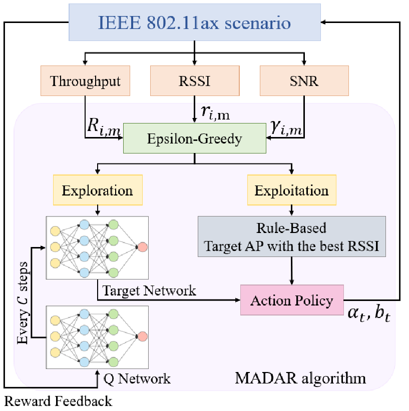
According to existing literature, machine learning techniques are often used to predict channel state information, enabling flexible and dynamic associations with potential APs. RL is a type of machine learning in which an agent learns a task through a trial-and-error method by interacting with a dynamic environment. The proposed MADAR scheme employs a multi-agent DQN architecture, which is designed based on macro-agents of STAs and micro-agents of states. Notably, unlike the general state-driven RL, we use epsilon-greedy to select actions, taking advantage of exploitation and exploration during the training phase.
As illustrated in Fig. 3, we collect the state from a real-time 802.11ax scenario. Note that is a matrix representing the information of each candidate AP. In the action selection phase, we deploy epsilon-greedy using the parameter . An epsilon-greedy agent may select an action with a sub-optimal state for low latency. Since our goal is to minimize delay, we allow this action to be learned by our network. Note that is the number of nodes in the candidate AP, and is the operating channel of the target AP. As time passes and epsilon changes, we expect the action policy to gradually transition to the DQN after a converged training. In the learning phase, we consider four deep neural network (DNN) layers as our hidden layers with neurons, and we select as our activation function in DNN layers. We fit the current state , next state , action , and reward into the DQN. Next, the gradient approach for the DQN optimizes the weight , which is calculated as
| (9) |
The mean-square error (MSE) is selected as a loss function for the DQN expressed as
| (10) |
where is a probability distribution over sequence , and
| (11) |
is the target reward in DQN. To determine which action yields the maximum reward, an agent must define the value of taking each action. The concrete procedure of MADAR scheme is demonstrated in Algorithm 1.
IV Performance Evaluations
We evaluate the proposed MADAR algorithm by using ns-3 simulations to verify our proposed system model, we deploy five channels in different frequencies with three APs. With standard IEEE 802.11ax, we consider a Wi-Fi 6 network as specified in Table I, with three APs in different operating channels and STAs, such that each STA is scattered randomly in area. The STA needs to background active scan intervals is ms. Note that the channel scan processdure and the handoff threshold is dB based on [24]. The handoff process will be mandatory implement when the current link quality of the associated AP is less than handoff threshold. Because we need STAs to be able to move under different AP transmission ranges, we set the maximum transmission range of the AP to meters, and the distance between each AP is set to meters.
| System Parameter | Value |
| Frequency | GHz, GHz |
| Number of channels () | |
| Number of AP () | |
| Channel bandwidth () | MHz |
| Distance between APs | meters |
| Propagation max range | meters |
| Interval of background active scan | ms |
| MinChannelTime () | ms |
| MaxChannelTime () | ms |
| Association timeout | ms |
| Learning rate () | |
| Exploration rate () | |
| Handoff threshold | dB |
| Packet error rate () |


In Figs. 4 and 4, we evaluate the association delays of the experiment using realistic AP setting (ERA), ns-3 network simulator (default 802.11ax protocol), epsilon-greedy, and our proposed MADAR scheme in different frequencies with STAs. Both the 802.11ax simulation and the ERA serve as our baseline, closely approximating real-world conditions. Once the neural network converges in our proposed scheme, we observe a higher tendency to select actions predicted by DQN rather than random selection. Note that the contention delay is included in each packet transmission time. As shown in Table III(b), our simulated Wi-Fi system in ns-3 closely resembles the delay obtained from ERA. We compare this scenario with other benchmark methods. From the data in the table, we can see that although Epsilon-Greedy effectively reduces the association delay, its random selection during exploration may still choose the worst-performing AP. On average, if extreme values exist, the delay improvement may not be significant. In contrast, our proposed MADAR scheme uses the neural network model for prediction during target AP exploration, avoiding extreme values and yielding better delay reduction than conventional 802.11 and other methods.
| Benchmark | ERA | 802.11ax | Epsilon-Greedy | MADAR |
| Max | 0.175 | 0.205 | 0.188 | 0.1375 |
| Min | 0.1052 | 0.1151 | 0.1145 | 0.1016 |
| Avg | 0.1387 | 0.148 | 0.1466 | 0.1178 |
| Benchmark | ERA | 802.11ax | Epsilon-Greedy | MADAR |
| Max | 0.2818 | 0.2754 | 0.2106 | 0.178 |
| Min | 0.112 | 0 .1005 | 0.1135 | 0.059 |
| Avg | 0.1492 | 0.1545 | 0.147 | 0.1105 |

Fig. 5 shows the maximum contention STAs comparison for the proposed MADAR scheme and conventional 802.11ax under different numbers of STAs with . Conventionally, the target AP selection is based solely on RSSI, which potentially leads to channel congestion and increased packet collision probability if most STAs choose the AP with the best RSSI. Our proposed MADAR method dynamically learns from the delayed reward and CSI returned by the Wi-Fi system, effectively achieving network load balancing and reducing channel contention-induced delays.

Fig. 6 displays the average data rate for the proposed MADAR scheme, benchmarked against the Epsilon-Greedy method [25] and conventional 802.11ax scheme. The Epsilon-Greedy method often chooses random APs, resulting in variable data rates in environments with a large number of STAs. Conventional 802.11ax has the worst performance in both frequency bands. Performance of MADAR varies with different epsilon values, as the epsilon parameter determines the proportion of DQN exploration (neural network) and exploitation (RSSI-based) at its early stage, eventually transitioning to full-DQN prediction. If epsilon is too small, useful actions may not be learned, leading to degraded results; if epsilon is too large, the learned features become random, which is similar to RSSI-based actions.

Fig. 7 demonstrates the performance comparison for the proposed MADAR scheme with varying epsilon and the conventional roaming method under different numbers of STAs. In cases with a large number of STAs, channel congestion and a high probability of packet collision arise due to too many STAs in the same channel. As a result, association request must be retransmitted multiple times for successful roaming, which results in increasing association delay. The advantages of the proposed MADAR scheme can be observed, as it strikes a balance in loading between operating channels.
V Conclusions
We have proposed the MADAR algorithm, which employs the deep Q-learning approach in an IEEE 802.11ax scenario to enhance Wi-Fi 6 roaming latency and rate through a decentralized control method. The MADAR-agent is designed to integrate the DQN and epsilon-greedy strategies, striking a compelling balance between exploration and exploitation by choosing between up-to-date and historical policies. Simulation results have demonstrated the potential benefits of the proposed MADAR algorithm in terms of network load balancing, packet error rate, and collision probability. By reducing dependence on APs or controllers, the MADAR algorithm, from the perspective of STA, is compatible with more devices supporting different standards and can enhance the potential benefits in the next-generation IEEE 802.11be standard, i.e., Wi-Fi 7.
References
- [1] Wi-Fi Alilance, “The Economic Value of Wi-Fi: A Global View (2021–2025),” Sept. 2021.
- [2] Z. Zhang, Y. Xiao, Z. Ma, M. Xiao, Z. Ding, X. Lei, G. K. Karagiannidis, and P. Fan, “6G Wireless Networks: Vision, Requirements, Architecture, and Key Technologies,” IEEE Vehicular Technology Magazine, vol. 14, no. 3, pp. 28–41, 2019.
- [3] L.-H. Shen, K.-T. Feng, and L. Hanzo, “Five Facets of 6G: Research Challenges and Opportunities,” ACM Computing Surveys, vol. 55, no. 11, pp. 1–39, 2023.
- [4] S. Bhattarai, G. Naik, and J.-M. J. Park, “Uplink Resource Allocation in IEEE 802.11ax,” in Proc. IEEE International Conference on Communications (ICC), 2019, pp. 1–6.
- [5] K.-H. Lee, “Using OFDMA for MU-MIMO User Selection in 802.11ax-Based WiFi Networks,” IEEE Access, vol. 7, pp. 186 041–186 055, 2019.
- [6] A. Mishra, M. Shin, and W. Arbaugh, “An Empirical Analysis of the IEEE 802.11 MAC Layer Handoff Process,” ACM SIGCOMM Computer Communication Review, vol. 33, no. 2, pp. 93–102, 2003.
- [7] L. Hao, B. Ng, and Y. Qu, “Self-optimizing Scanning Parameters for Seamless Handover in IEEE 802.11 c,” in Proc. IEEE Conference on Local Computer Networks (LCN), 2018, pp. 335–342.
- [8] D.-J. Deng, Y.-P. Lin, X. Yang, J. Zhu, Y.-B. Li, J. Luo, and K.-C. Chen, “IEEE 802.11ax: Highly Efficient WLANs for Intelligent Information Infrastructure,” IEEE Communications Magazine, vol. 55, no. 12, pp. 52–59, 2017.
- [9] K.-H. Lee, “Using OFDMA for MU-MIMO User Selection in 802.11ax-Based WiFi Networks,” IEEE Access, vol. 7, pp. 186 041–186 055, 2019.
- [10] K. Kosek-Szott and K. Domino, “An Efficient Backoff Procedure for IEEE 802.11ax Uplink OFDMA-Based Random Access,” IEEE Access, vol. 10, pp. 8855–8863, 2022.
- [11] L.-H. Shen, K.-H. Liao, and K.-T. Feng, “Queue-Aware Uplink Arbitration-based Contention and Downlink Resource Allocation for Multi-APs for IEEE 802.11ax WLANs,” in Proc. IEEE Wireless Communications and Networking Conference (WCNC), 2022, pp. 1755–1760.
- [12] M. I. Sanchez and A. Boukerche, “On IEEE 802.11k/r/v amendments: Do they have a real impact?” in IEEE Wireless Communications, vol. 23, 2016, pp. 48–55.
- [13] A. Fink, R. S. Mogensen, I. Rodriguez, T. Kolding, A. Karstensena, and G. Pocovi, “Empirical Performance Evaluation of Enterprise Wi-Fi for IIoT Applications Requiring Mobility,” in Proc. IEEE European Wireless Conference, 2021, pp. 1–8.
- [14] Z. Lin, Z. Ni, L. Kuang, C. Jiang, and Z. Huang, “Dynamic Beam Pattern and Bandwidth Allocation Based on Multi-Agent Deep Reinforcement Learning for Beam Hopping Satellite Systems,” IEEE Transactions on Vehicular Technology, vol. 71, no. 4, pp. 3917–3930, 2022.
- [15] F. Wilhelmi, B. Bellalta, C. Cano, and A. Jonsson, “Implications of Decentralized Q-Learning Resource Allocation in Wireless Networks,” in arXiv:1705.10508 [cs.NI], 2017.
- [16] P. V. Klaine, M. A. Imran, O. Onireti, and R. D. Souza, “A Survey of Machine Learning Techniques Applied to Self-Organizing Cellular Networks,” IEEE Communications Surveys & Tutorials, vol. 19, no. 4, pp. 2392–2431, 2017.
- [17] Q. Mao, F. Hu, and Q. Hao, “Deep Learning for Intelligent Wireless Networks: A Comprehensive Survey,” IEEE Communications Surveys & Tutorials, vol. 20, no. 4, pp. 2595–2621, 2018.
- [18] N. C. Luong, D. T. Hoang, S. Gong, D. Niyato, P. Wang, Y.-C. Liang, and D. I. Kim, “Applications of Deep Reinforcement Learning in Communications and Networking: A Survey,” IEEE Communications Surveys & Tutorials, vol. 21, no. 4, pp. 3133–3174, 2019.
- [19] L.-H. Shen, T.-W. Chang, K.-T. Feng, and P.-T. Huang, “Design and Implementation for Deep Learning Based Adjustable Beamforming Training for Millimeter Wave Communication Systems,” IEEE Transactions on Vehicular Technology, vol. 70, no. 3, pp. 2413–2427, 2021.
- [20] T.-W. Chang, L.-H. Shen, and K.-T. Feng, “Learning-Based Beam Training Algorithms for IEEE802.11ad/ay Networks,” in Proc. IEEE Vehicular Technology Conference (VTC-Spring), 2019, pp. 1–5.
- [21] R. Ahmad, M. D. Soltani, M. Safari, A. Srivastava, and A. Das, “Reinforcement Learning Based Load Balancing for Hybrid LiFi WiFi Networks,” IEEE Access, vol. 8, pp. 132 273–132 284, 2020.
- [22] V. Aruna, L. Anjaneyulu, and C. Bhar, “Deep-Q Reinforcement Learning based Resource Allocation in Wireless Communication Networks,” in Proc. IEEE International Symposium on Smart Electronic Systems (iSES), 2022, pp. 66–72.
- [23] H. Wu, S. Cheng, Y. Peng, K. Long, and J. Ma, “IEEE 802.11 Distributed Coordination Function (DCF): Analysis and Enhancement,” in Proc. IEEE International Conference on Communications (ICC), vol. 1, 2002, pp. 605–609 vol.1.
- [24] J. Teng, C. Xu, W. Jia, and D. Xuan, “D-Scan: Enabling Fast and Smooth Handoffs in AP-Dense 802.11 Wireless Networks,” in Proc. IEEE International Conference on Computer Communications (INFOCOM), 2009, pp. 2616–2620.
- [25] A. Idris, A. Samaon, and M. S. Idris, “Performance Analysis of Resource Allocation Downlink for MIMO-OFDMA System using Greedy Algorithm,” in Proc. IEEE International Conference on Control System, Computing and Engineering (ICCSCE), 2016, pp. 157–162.