Inducing or suppressing the anisotropy in multilayers based on CoFeBPreprint: AIP/123-QED
Abstract
Controlling the uniaxial magnetic anisotropy is of practical interest to a wide variety of applications. We study Co40Fe40B20 single films grown on various crystalline orientations of LiNbO3 substrates and on oxidized silicon. We identify the annealing conditions that are appropriate to induce or suppress uniaxial anisotropy. Anisotropy fields can be increased by annealing up to 11 mT when using substrates with anisotropic surfaces. They can be decreased to below 1 mT when using isotropic surfaces. In the first case, the observed increase of the anisotropy originates from the biaxial strain in the film caused by the anisotropic thermal contraction of the substrate when back at room temperature after strain relaxation during annealing. In the second case, anisotropy is progressively removed by applying successive orthogonal fields that are assumed to progressively suppress any chemical ordering within the magnetic film. The method can be applied to CoFeB/Ru/CoFeB synthetic antiferromagnets but the tuning of the anisotropy comes with a decrease of the interlayer exchange coupling and a drastic change of the exchange stiffness.
I Introduction
The control of the anisotropy of a given magnetic material is very often required in the applications of magnetism Hirohata et al. 2020. The amorphous metallic CoFeB films are widely used in spintronics, both when very soft properties are desired such as in flux guides Smith et al. 1991, or in contrast when a well defined uniaxial anisotropy is wanted as in the free layers of magnetoresistive field sensors Hirohata et al. 2020. Depending on the targeted applications, a very same material platform can even be sometimes used with opposite requirements for anisotropy. This is the case of artificial multiferroics composed of ferromagnetic films and piezoelectric layers. When meant for instance for energy harvesting, they require a well defined anisotropy Roy et al. 2011 while when meant for racetrack applications isotropic properties are welcomeLei et al. 2013. Tailoring the uniaxial anisotropy –both inducing and suppressing– is thus an important challenge of technological interest.
Various knobs can be employed to tune the magnetic anisotropy. Interface engineering can be used in ultrathin filmsO’Handley 1999; Chappert et al. 1998. In bulk materials one can either rely (i) on some sort of chemical ordering van de Riet et al. 1997 or, (ii) on the induction of anisotropic strain in magnetostrictive materials Mathews and Prestigiacomo 2023.
In the first case, one use generally saturates the magnetization using a strong magnetic field, and then provide thermal energy (hence atomic mobility) to let the structure of the material evolve towards a new state compatible with the desired magnetization orientation Chikazumi 2009. In metallic glass like CoFeB, the anisotropy is related to some degree of alignment of the Boron atoms within the material and this can be effectively tuned and reoriented by in-field annealing van de Riet et al. 1997. For the same reason, magnetic anisotropy can already be induced during deposition if done under an applied field West 1964.
The second case applies to magnetostrictive materials only. There, if an appropriate choice of the substrate influences the growth (e.g. epitaxy or strain relaxation) the resulting anisotropic strain leads to magnetic anisotropy Mathews and Prestigiacomo 2023. This elastic coupling between the magnetic film and the substrate is systematically desired in SAW-FMR devices Weiler et al. 2011; Kuszewski et al. 2018; Rovillain et al. 2022 and magneto-acoustics Küß et al. 2022 when one harnesses the interaction between a surface acoustic wave (SAW) hosted by a piezoelectric substrate and the ferromagnetic resonance (FMR) of the magnetic film. Note that this situation fundamentally entails a dilemma when isotropic properties (meaning often stress-free layers) are desired in addition to a tight elastic coupling between film and substrate. This dilemma is significant in SAW-FMR of synthetic antiferromagnets (SAFs) since in this case a vanishing anisotropy is required for resonant coupling between the SAWs and the spin wavesVerba et al. 2019. Unfortunately it is difficult to obtain quasi-isotropic SAFs, one typically is left with uniaxial anisotropy fields that remain above a couple of mT Hindmarch et al. 2008; Rushforth et al. 2008; González-Guerrero et al. 2007; Chang et al. 2021.
In this paper, we study how to tailor (increase or suppress) the magnetic anisotropy of magnetostrictive layers grown on piezoelectric substrates. We develop our method on Co40Fe40B20 single layer films on LiNbO3 single crystals that are very adequate for rf acoustical waves. We show that our method is applicable to SAFs. The paper is organized as follows. We initially quantify the uniaxial anisotropy in CoFeB and show how to control it through appropriate annealing and substrate choice. The surface orientation of LiNbO3 strongly impacts how the annealing alters the anisotropy of the magnetic material. A well designed procedure can lead to quasi-isotropic CoFeB layers, and can be extend to CoFeB/Ru/CoFeB SAFs. However, spin wave spectroscopy experiments show that the tailoring of the anisotropy of the SAF comes together with an evolution of the exchange stiffness and of the interlayer exchange coupling.
II Experiments

II.1 Films
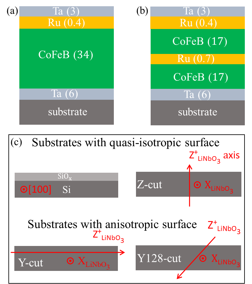
Fig. 1 depicts our material systems. The magnetic stacks are : Ta(6, buffer)/CoFeB(34)/Ru(0.4)/Ta(3, cap) (short name: single CoFeB) and Ta(6, buffer)/CoFeB(17)/Ru(0.7)/CoFeB(17)/Ru(0.4)/Ta(3, cap) (short name: CoFeB/Ru/CoFeB) SAF. All thicknesses are given in nm. The CoFeB layer was deposited from a Co40Fe40B20 (at. %) target. The deposition is done at room temperature by dc-magnetron sputtering at pressure of argon of mbar and base pressure below mbar. No intentional magnetic field is applied during growth. The thickness of the Ru(0.7) spacer of the SAF is chosen to maximize the interlayer exchange coupling Mouhoub et al. 2022.
II.2 Substrates
The depositions were done on several substrates ranging from naturally oxidized silicon wafers (to be referred as Si/SiO) to LiNbO3 single crystals of various surface orientation (Z-, Y- and Y128-cut) Kushibiki et al. 2002. Since the properties of the magnetic materials can be impacted by the stress induced by the underlying substrateBartasyte et al. 2012, we cast the substrates in two categories. The first category gathers the substrates whose surface expands in a quasi-isotropic manner upon annealing. For the second category the thermal expansion is anisotropic at the surface, as illustrated in Fig. 1(c).
II.3 Post-growth annealing conditions
In order to unravel the respective roles of substrate induced applied stress, applied field, and Boron diffusion onto the annealing-induced evolution of the magnetic properties, we have annealed our material systems using 4 different procedures:
- •
without any applied magnetic field.
- •
with a 70 mT applied in a given direction in a 1 step manner. We will see that the field direction (i.e., along or orthogonal to the initial anisotropy axis) shall not influence the final result.
- •
With a 70 mT field applied in 2 successive steps: the sample is first annealed with a field oriented at some randomly chosen in-plane direction, then at along an orthogonal direction.
- •
In a 30 mT field rotating at 5 rpm in the sample plane.
The annealing temperature ranges from 100 to 200 °C, above which systematic crystallization is expected for our Boron content You et al. 2008; Conca et al. 2014; Devolder et al. 2018; Sriram et al. 2022. The annealing time is set to 4 min on a hot plate for (i), (ii) and (iii). The annealing in rotating field (iv) is done in vacuum for 10 h. In all cases the field is applied while ramping up and down the temperature and is strong enough to saturate the magnetization.
II.4 Magnetic characterizations
The magnetic characterization of samples was performed by vibrating sample magnetometry (VSM) and Vector Network Analyzer ferromagnetic resonance Bilzer et al. 2007 (VNA-FMR). An in-plane applied field was used, and its direction [see Fig. 2(a)] was varied to access to the sample’s magnetic anisotropy. The resonance spectra (FMR absorption signal) are obtained by measuring the field dependence of the VNA transmission parameter , as plotted in Fig. 2(b). The resonance frequencies (FMR for the single CoFeB or acoustical and optical resonances of the SAF) are defined from the maxima of absorption.
The -dependence of the FMR of single CoFeB films were analyzed in the macrospin approximation using numerical energy minimization and subsequent application the Smit-Beljers equationSmit and Beljers 1995. A fitting procedure allowed to extract independently the values of the uniaxial anisotropy field , the orientation of the easy axis and the saturation magnetization . Fig. 2(c) illustrates this procedure when applied to a single CoFeB film grown on a Y128-cut substrate in the as-grown state. The orientation of the easy axis and the uniaxial character of the anisotropy are systematically consistent with the hysteresis loops.
The and dependence of the acoustical and optical resonances of the SAF were analyzed in the full micromagnetic framework Vansteenkiste et al. 2014 following the method described in ref. Mouhoub et al. 2022. There, it was shown that the competition between the interlayer coupling and the intralayer exchange stiffness results in the existence of a gradient of the magnetization orientation in the growth direction. This gradient renders the curvature of the near very sensitive to the ratio of and , that can thus be deduced reliably. A fitting procedure of can then be used to extract the anisotropy fields, assumed to be exactly the same for the two magnetic layers of the SAF.
III Evolution of the magnetic anisotropy upon annealing
III.1 Results

The main features of the evolution of the magnetic anisotropy upon annealing are illustrated in Fig. 3 and compiled in Table 1. An annealing temperature above 100°C appeared necessary to observe an evolution of the magnetic properties. The atomic mobility within the CoFeB films is likely insufficient below this temperature. For larger annealing temperatures, the magnetic anisotropy evolves in very different ways depending if the substrate has an isotropic or an anisotropic surface, and also on the field applied.
When working on substrates with anisotropic surfaces (Y-cut and Y128-cut LiNbO3), the annealing increases substantially the anisotropy, see Fig. 3(a). The inset compares for instance the angular dependence of the FMR of a CoFeB film on a Y-cut LiNbO3 substrate before and after a 200 °C field-free annealing. Annealing increases the anisotropy field from 3.05 mT to 9.00 mT. This comes with a reorientation of the hard axis towards the X (i.e., = 0 deg. in our convention). The Y128-cut samples follow a similar trend but with a lower increase of the anisotropy. As soon as the anisotropy increases, the hard axis also reorients towards X axis and the easy axis towards the in-plane projection of the Z axis. When working on these substrates with anisotropic surfaces, the magnetic field applied (or not) during the annealing has a minor influence on the evolution of the magnetic anisotropy.
Conversely, the anisotropy can be reduced for the films grown on the substrates with quasi-isotropic surfaces: Z-cut LiNbO3 and oxidized silicon. The inset in Fig. 3(b) shows for instance angular dependence of the FMR before and after a 2 steps annealing procedure in the case of a Z-cut LiNbO3 substrate. This 2-step annealing lowers the anisotropy down to 0.6 mT. Notably, the rate of decrease of the anisotropy depends strongly on the field sequence used during annealing, and the hard axis systematically ends perpendicular to the field applied during the last annealing step.
III.2 Physical origins of the evolution of anisotropy
The previous results can be discussed by considering two thermodynamic phenomena: (i) the interplay between magneto-elasticity and anisotropic strain and, (ii) the chemical ordering within the magnetic material. We recall that for the annealing temperatures studied here, no crystallization of the CoFeB layer is expected. Let us first discuss the magneto-elastic scenario.
| Sub. | Thermal | (mT) | Hard axis | (T) |
| treatment | ||||
| Substrates with quasi-isotropic surface: | ||||
| SiOx | as grown | 3.0 | variable | 1.70 |
| 200∘C, H=0 | 3.1 | variable | 1.72 | |
| 200∘C, rotH | 1.5 | variable | 1.71 | |
| 200∘C 2-step H | 0.9 | to last field | 1.76 | |
| Z | as grown | 2.2 | variable | 1.70 |
| 200∘C, H=0 | 2.8 | variable | 1.71 | |
| 200∘C, rotH | 2.4 | variable | 1.82 | |
| 200∘C 2-step H | 0.6 | to last field | 1.70 | |
| Substrates with anisotropic surface: | ||||
| Y128 | as grown | 3.1 | variable | 1.77 |
| 200∘C, H=0 | 4.3 | X | 1.87 | |
| Y | as grown | 3.0 | variable | 1.70 |
| 200∘C, H=0 | 9.0 | X | 2.00 | |
| 200∘C, rotH | 6.4 | X | 2.00 | |
| 200∘C 2-stepH | 11.4 | X | 2.00 | |
III.2.1 Magneto-elastic scenario
When annealing above 100°C, the atoms within the CoFeB film acquire some mobility, as observed in other soft magnetic materials van de Riet et al. 1997. Being amorphous, the glassy CoFeB film slowly flows, such that after a sufficient delay it reaches a relaxed (stress-free) state at the annealing temperature. Cooling (defining ) to room temperature (RT) quenches suddenly any atomic mobility, while triggering a thermal contraction. Since the CoFeB film is clamped by the much thicker substrate, the in-plane strain of the substrate is imposed to the magnetic film. The natural contraction of an hypothetically free-standing CoFeB film would be isotropic (its thermal expansion coefficient is isotropic). That of the LiNbO3 substrate is not: the thermal expansion coefficient in the X direction is stronger than in the other direction of the substrate plane Bartasyte et al. 2012. As a result the stress within the CoFeB at RT is biaxial and more compressive in the X direction. Defining and as the two directions of the surface of the substrate with X [see Fig. 1(c)], we have:
| (1) |
Whatever the substrate cut, the largest deformation is always along X, see ref. Bartasyte et al. 2012. We have for both the Y-cut case and the Y128-cut case. As the CoFeB has essentially a free surface, its stress is purely biaxial, such that there is no shear strain (i.e., ).
This biaxial strain generates a magnetic anisotropy of CoFeB. Indeed for an in-plane magnetized film, the magneto-elastic energy is , where and are the usual magneto-elastic coefficients. In amorphous materials, they reduce to which amounts to MJ/m3 with the magnetostriction coefficient for Co40Fe40B20 from ref. Masciocchi et al. 2021 and the Young’s modulus GPa, from ref. Peng et al. 2016. Note that , meaning a tensile strain lowers the energy. The CoFeB film being more compressed in the X-direction than in other directions, X will become the hard axis. Using the conservation of the magnetization norm and , we can rewrite this energy in the form of an effective uniaxial anisotropy:
| (2) |
with a magneto-elastic effective anisotropy field of:
| (3) |
that is predicted to be linear with the annealing temperature, which bears some similarity with the experimental results [see Fig. 3(a)] above =100°C.
| Surface | in first direction | along a perp direction |
|---|---|---|
| Y-cut | along X: | along X: |
| Y128-cut | along X: | |
| Z-cut | along X: | along X: |
| Si[001] | along [100]: 0.468 | along [010]: 0.468 |
Using the data of Table 2 with K, Eq. 3 predicts for the Y128-cut case and for the Y-cut case, with hard axes along X in both cases. This magneto-elastic contribution dominates any other contribution to the uniaxial anisotropy, including the one present in the as-grown state and those possibly related to the magnetic field applied during the annealing. This correlates with our finding on the minor influence of the field applied during the annealing of Y-cut and Y128 samples Note that the predicted values of the anisotropy field are slightly marger than our experimental findings. This may indicate that the stress release is incomplete during the annealing, or that the magnetostriction coefficient of the literature Masciocchi et al. 2021 is over estimated.
Another conclusion of our study concerns the evolution of the magnetization upon annealing (Table 1). There is little evolution for the Si/SiO case, but a substantial increase otherwise. For our nominal Boron concentration, bulk crystallisation or stress-induced bulk crystallization are not supposed to occur at our annealing temperatures Trexler and Thadhani 2010 and can therefore not be invoked for the observed increase of the magnetization. However, some compression-induced diffusion of the Boron atoms out of the magnetic films may start to occur, thereby reducing the Boron concentration. The corresponding densification is generally associated with an increase of the magnetization Kim et al. 2022. We indeed observe that the increase of the magnetization after the 200°C annealings seems to correlate with the amount of compression (see Tables 1 and 2).
This anisotropic strain-induced scenario is effective only for the substrates with anisotropic thermal expansion like Y-cut and Y128-cut LiNbO3. Another scenario must thus be invoked for the Z-cut of LiNbO3 and the oxidized silicon cases.
III.2.2 Chemical order scenario
In many magnetic alloys, it is routinely observed that annealing in a magnetic field induces a preferred direction of magnetization O’Handley 1999; Chikazumi 2009. A plausible model often invoked to explain this mechanism is the migration of atoms on a local scale in such a way as to favor magnetization in a given direction. At annealing temperatures leading to some atomic mobility, some atom pairs orient themselves relative to the direction of magnetization set by the field, so as to decrease their magnetic anisotropy energy. Cooling to a temperature where atomic diffusion gets quenched, the anisotropy axis remains along the direction it has acquired during annealing. Metalloids like Boron play an important role in this process thanks to their high mobility and chemical interaction with transition metals van de Riet et al. 1997. In metallic glass like CoFeB the applied field drives an anisotropic distribution of atoms pairs among Co, Fe and B, and this mechanism is active at the time scales used for annealing for the temperatures considered here van de Riet et al. 1997. This process is generally used to induce anisotropy, using a fixed field orientation and a long annealing.
However it is important to figure out that the material evolution is a thermodynamical process: during our first annealing step, the field-induced (energy-minimization-driven) chemical ordering process competes with a temperature-induced (random, entropy-driven) disordering trend. This competition leads to a slow formation of a uniaxial anisotropy. During the subsequent annealing step, the magnetic field orientation is different. As a result, the entropy-driven and energy-driven thermodynamical forces both tend to destroy the previously favored chemical order, and therefore they concur to reduce the anisotropy. Because of this coincidence of the two thermodynamical forces at play, this destruction of the previously set anisotropy is a fast process. The building-up of any uniaxial anisotropy along a new field direction is a much slower process. In practice, it is not seen at the time scales used in our annealings.
This explains how one can progressively reduce the anisotropy by applying successive orthogonal fields during annealing when there is no magneto-elastic contribution at play. Each annealing step with a new field direction statistically breaks pair alignments which results in a progressive randomization of the chemical ordering within the magnetic film and, thus, a decrease of the anisotropy. The effect of annealing under a rotating field is qualitatively similar as a two-step annealing, but their relative efficiency depends on the characteristic time-scales of atomic diffusion versus the field rotation period.
To summarize the discussion so far, the findings presented in Fig. 3 indicate that, with regards to the substrate, different contributions to the uniaxial anisotropy of CoFeB may arise. For surface substrates with anisotropic thermal expansion (Y-cut and Y128-cut LiNbO3), the anisotropy is controlled by anisotropic strain, while for quasi-isotropic surface substrates (Si/SiO and Z-cut LiNbO3), the anisotropy is controlled by the chemical ordering favored or broken by the sequence of applied magnetic fields.
IV Applicability to synthetic antiferromagnets

It is important to investigate whether the conclusions previously established for single CoFeB films can be extended to multilayers. In particular, let us see if one can obtain isotropic CoFeB/Ru/CoFeB synthetic antiferromagnets (SAF) when grown on quasi-isotropic substrates. Fig. 4 shows the results for a SAF grown on Si/SiO in the as-grown state and after annealing in a rotating field. The two lowest order spin wave modes can be detected, the acoustical () and the optical () modes. The value of at low field is known to be very sensitive on the anisotropy fieldDevolder and Ito 2012. The -dependence of [Fig.4(a)] clearly indicates that the annealing procedure defined for the single layer films succeeded also in suppressing the anisotropy of the SAF grown on Si/SiO. As shall be explained later, we can only give a semi-quantitative measurement the anisotropy field of the SAF, but its reduction (see Table 3) is almost complete. The same trend is observed when the growth is performed on Z-cut LiNbO3 (see Table 3).
However this quasi-suppression of the anisotropy is accompanied by an evolution of the other magnetic properties. This can be seen by comparing the frequencies of the experimental and simulated modes using the methodology defined in ref. Mouhoub et al. 2022. Indeed the value of at is essentially set by the interlayer coupling . Annealing obviously reduces it [compare Fig. 4(b) and (c)]. Besides, the curvature of versus is very sensitive to the ratio : annealing obviously strongly affects this ratio.
The values of , that best fit the experimental data for Si/SiO and Z-cut LiNbO3 substrates are listed in Table 3. The experiment-to-micromagnetics agreement is excellent except in the small field region for the acoustical spin wave, where micromagnetics systematically underestimates the frequency of the acoustical mode [Fig. 4(b) and (c)]. The same difficulty arises when attempting to account for the -dependence of with micromagnetic simulations, as shown in Fig. 4(a). The reason for this disagreement was not identified, but we believe that it may arise from a gradient of the magnetic properties in the growth direction which is not taken into account in the simulations. For this reason, we can only give a semi-quantitative measurement the anisotropy field . The anisotropy values in Table 3 are deduced from the sole value of at zero field.
| Substrate | (mT) | (T) | (mJ/m2) | (pJ/m) |
| SiOx, as grown | 4.4 | 1.70 | -1.5 | 14.5 |
| SiOx, 200∘C | 0.8 | 1.71 | -0.9 | 28.3 |
| Z, as grown | 3.8 | 1.70 | -1.7 | 15.5 |
| Z, 200∘C | 0.5 | 1.70 | -1.1 | 21 |
Upon annealing, reduces from -1.5 mJ/m2 to -0.9 mJ/m2 upon annealing, as observed for our SAF grown on Si/SiO. The atomic mobility enabled by the annealing probably reduces the sharpness of the interfaces of the Ru spacer, thereby decreasing . The evolution of the local order within the CoFeB material is also evident from the evolution of its exchange stiffness , which undergoes a very substantial increase from 14.5 pJ/m to 28.3 pJ/m upon annealing. It is noteworthy that the as-grown value of is comparable to literature values in the amorphous state for our composition, which are found to be Mouhoub et al. 2022; Cho et al. 2013; Choi 2020 in the range from 10 to 14 pJ/m. The exchange stiffness is also known to increase substantially when the layer get either crystalline or simply more dense Kim et al. 2022.
V Conclusion
We have studied the impact of annealing on the magnetic properties of CoFeB films and synthetic antiferromagnets. We identified the different contributions to the uniaxial anisotropy in CoFeB single films by performing various in-field thermal treatments for films grown on different substrates. The anisotropy field of CoFeB can be increased when the annealing is performed in samples grown on substrates whose surfaces have an anisotropic thermal expansion. In this case the likely scenario is a full stress relaxation occurring during the annealing, followed by the creation of a biaxial strain in the CoFeB upon cooling, which induces a strong magneto-elastic anisotropy. Anisotropy fields up to 11 mT can be induced when extremely anisotropic substrates like Y-cut LiNbO3 are used. Conversely, the anisotropy field can be decreased to below 1 mT when using substrates whose surface is quasi-isotropic. In this case the anisotropy is controlled by the history of the magnetic field applied during annealing. In particular, sequences of orthogonal fields are very efficient in suppressing the anisotropy. This method was applied to obtain isotropic CoFeB/Ru/CoFeB synthetic antiferromagnets; however the annealing also affects the exchange interactions within the stack.
Acknowledgements.
We acknowledge discussions with S. Margueron and A. Bartasyte. This work was supported by a public grant overseen by the French National Research Agency (ANR) as part of the “Investissements d’Avenir” program (Labex NanoSaclay, reference: ANR-10-LABX-0035, project SPICY). R. L. S and F. M. acknowledge the French National Research Agency (ANR) under Contract No. ANR-20-CE24-0025 (MAXSAW).References
References
- Hirohata et al. (2020) Atsufumi Hirohata, Keisuke Yamada, Yoshinobu Nakatani, Ioan-Lucian Prejbeanu, Bernard Diény, Philipp Pirro, and Burkard Hillebrands, “Review on spintronics: Principles and device applications,” Journal of Magnetism and Magnetic Materials 509, 166711 (2020).
- Smith et al. (1991) Neil Smith, Fred Jeffers, and Jay Freeman, “A high-sensitivity magnetoresistive magnetometer,” Journal of Applied Physics 69, 5082–5084 (1991), https://doi.org/10.1063/1.348130 .
- Roy et al. (2011) Kuntal Roy, Supriyo Bandyopadhyay, and Jayasimha Atulasimha, “Hybrid spintronics and straintronics: A magnetic technology for ultra low energy computing and signal processing,” Applied Physics Letters 99, 063108 (2011), https://doi.org/10.1063/1.3624900 .
- Lei et al. (2013) Na Lei, Thibaut Devolder, Guillaume Agnus, Pascal Aubert, Laurent Daniel, Joo-Von Kim, Weisheng Zhao, Theodossis Trypiniotis, Russell P. Cowburn, Claude Chappert, Dafiné Ravelosona, and Philippe Lecoeur, “Strain-controlled magnetic domain wall propagation in hybrid piezoelectric/ferromagnetic structures,” Nature Communications 4, 064043 (2013).
- O’Handley (1999) R. C. O’Handley, Modern Magnetic Materials: Principles and Applications (Wiley-Interscience, 1999).
- Chappert et al. (1998) C. Chappert, H. Bernas, J. Ferré, V. Kottler, J.-P. Jamet, Y. Chen, E. Cambril, T. Devolder, F. Rousseaux, V. Mathet, and H. Launois, “Planar patterned magnetic media obtained by ion irradiation,” Science 280, 1919–1922 (1998), https://www.science.org/doi/pdf/10.1126/science.280.5371.1919 .
- van de Riet et al. (1997) E. van de Riet, W. Klaassens, and F. Roozeboom, “On the origin of the uniaxial anisotropy in nanocrystalline soft-magnetic materials,” Journal of Applied Physics 81, 806–814 (1997), https://doi.org/10.1063/1.364164 .
- Mathews and Prestigiacomo (2023) Scott A. Mathews and Joseph Prestigiacomo, “Controlling magnetic anisotropy in nickel films on linbo3,” Journal of Magnetism and Magnetic Materials 566, 170314 (2023).
- Chikazumi (2009) S. Chikazumi, Physics of Ferromagnetism, International Series of Monographs on Physics (OUP Oxford, 2009).
- West (1964) Forrest G. West, “Uniaxial anisotropy due to magnetoelastic energy in constrained polycrystalline films,” Journal of Applied Physics 35, 1827–1840 (1964), https://doi.org/10.1063/1.1713750 .
- Weiler et al. (2011) M. Weiler, L. Dreher, C. Heeg, H. Huebl, R. Gross, M. S. Brandt, and S. T. B. Goennenwein, “Elastically driven ferromagnetic resonance in nickel thin films,” Phys. Rev. Lett. 106, 117601 (2011).
- Kuszewski et al. (2018) P. Kuszewski, J.-Y. Duquesne, L. Becerra, A. Lemaître, S. Vincent, S. Majrab, F. Margaillan, C. Gourdon, and L. Thevenard, “Optical probing of rayleigh wave driven magnetoacoustic resonance,” Phys. Rev. Appl. 10, 034036 (2018).
- Rovillain et al. (2022) Pauline Rovillain, Jean-Yves Duquesne, Louis Christienne, Mahmoud Eddrief, Maria Gloria Pini, Angelo Rettori, Silvia Tacchi, and Massimiliano Marangolo, “Impact of spin-wave dispersion on surface-acoustic-wave velocity,” Phys. Rev. Appl. 18, 064043 (2022).
- Küß et al. (2022) M. Küß, M. Albrecht, and M. Weiler, “Chiral magnetoacoustics,” Front. Phys. 10 (2022), https://doi.org/10.3389/fphy.2022.981257.
- Verba et al. (2019) Roman Verba, Vasil Tiberkevich, and Andrei Slavin, “Wide-band nonreciprocity of surface acoustic waves induced by magnetoelastic coupling with a synthetic antiferromagnet,” Phys. Rev. Appl. 12, 054061 (2019).
- Hindmarch et al. (2008) A. T. Hindmarch, C. J. Kinane, M. MacKenzie, J. N. Chapman, M. Henini, D. Taylor, D. A. Arena, J. Dvorak, B. J. Hickey, and C. H. Marrows, “Interface induced uniaxial magnetic anisotropy in amorphous cofeb films on algaas(001),” Phys. Rev. Lett. 100, 117201 (2008).
- Rushforth et al. (2008) A. W. Rushforth, E. De Ranieri, J. Zemen, J. Wunderlich, K. W. Edmonds, C. S. King, E. Ahmad, R. P. Campion, C. T. Foxon, B. L. Gallagher, K. Výborný, J. Kučera, and T. Jungwirth, “Voltage control of magnetocrystalline anisotropy in ferromagnetic-semiconductor-piezoelectric hybrid structures,” Phys. Rev. B 78, 085314 (2008).
- González-Guerrero et al. (2007) Miguel González-Guerrero, José Luis Prieto, David Ciudad, Pedro Sánchez, and Claudio Aroca, “Engineering the magnetic properties of amorphous (fe80co20)80b20 with multilayers of variable anisotropy direction,” Applied Physics Letters 90, 162501 (2007), https://doi.org/10.1063/1.2724752 .
- Chang et al. (2021) H. W. Chang, F. T. Yuan, D. Y. Lin, D. H. Tseng, W. C. Chang, Y. S. Chen, and J. G. Lin, “Large stress-induced anisotropy in soft magnetic films for synthetic spin valves,” Applied Physics Letters 119, 242402 (2021), https://doi.org/10.1063/5.0070033 .
- Mouhoub et al. (2022) A. Mouhoub, F. Millo, C. Chappert, J. V. Kim, J. Létang, A. Solignac, and T. Devolder, “Exchange energies in cofeb/ru/cofeb synthetic antiferromagnets,” (2022).
- Kushibiki et al. (2002) J. Kushibiki, I. Takanaga, S. Komatsuzaki, and T. Ujiie, “Chemical composition dependences of the acoustical physical constants of linbo3 and litao3 single crystals,” Journal of Applied Physics 91, 6341–6349 (2002), https://aip.scitation.org/doi/pdf/10.1063/1.1467608 .
- Bartasyte et al. (2012) A. Bartasyte, V. Plausinaitiene, A. Abrutis, T. Murauskas, P. Boulet, S. Margueron, J. Gleize, S. Robert, V. Kubilius, and Z. Saltyte, “Residual stresses and clamped thermal expansion in linbo3 and litao3 thin films,” Applied Physics Letters 101, 122902 (2012), https://doi.org/10.1063/1.4752448 .
- You et al. (2008) C. Y. You, T. Ohkubo, Y. K. Takahashi, and K. Hono, “Boron segregation in crystallized mgo/amorphous-co40fe40b20 thin films,” Journal of Applied Physics 104, 033517 (2008), https://doi.org/10.1063/1.2963709 .
- Conca et al. (2014) A. Conca, E. Th. Papaioannou, S. Klingler, J. Greser, T. Sebastian, B. Leven, J. Lösch, and B. Hillebrands, “Annealing influence on the gilbert damping parameter and the exchange constant of cofeb thin films,” Applied Physics Letters 104, 182407 (2014), https://doi.org/10.1063/1.4875927 .
- Devolder et al. (2018) Thibaut Devolder, Joo-Von Kim, J. Swerts, S. Couet, S. Rao, W. Kim, S. Mertens, G. Kar, and V. Nikitin, “Material developments and domain wall-based nanosecond-scale switching process in perpendicularly magnetized stt-mram cells,” IEEE Transactions on Magnetics 54, 1–9 (2018).
- Sriram et al. (2022) K. Sriram, Jay Pala, Rohiteswar Mondal, Bibekananda Paikaray, Komal Jain, G. A. Basheed, Arabinda Haldar, and Chandrasekhar Murapaka, “Effect of annealing on magnetization reversal and spin dynamics in co40fe40b20 thin films,” Journal of Superconductivity and Novel Magnetism 36, 155–162 (2022).
- Bilzer et al. (2007) C. Bilzer, T. Devolder, P. Crozat, C. Chappert, S. Cardoso, and P. P. Freitas, “Vector network analyzer ferromagnetic resonance of thin films on coplanar waveguides: Comparison of different evaluation methods,” Journal of Applied Physics 101, 074505 (2007), https://doi.org/10.1063/1.2716995 .
- Smit and Beljers (1995) J. Smit and H. G. Beljers, “Ferromagnetic resonance absorption in, bafe12019, a highly anisotropic crystal,” Philips Res. Rep. 10, 113–130 (1995).
- Vansteenkiste et al. (2014) Arne Vansteenkiste, Jonathan Leliaert, Mykola Dvornik, Mathias Helsen, Felipe Garcia-Sanchez, and Bartel Van Waeyenberge, “The design and verification of MuMax3,” AIP Advances 4, 107133 (2014).
- Masciocchi et al. (2021) Giovanni Masciocchi, Mouad Fattouhi, Andreas Kehlberger, Luis Lopez-Diaz, Maria-Andromachi Syskaki, and Mathias Kläui, “Strain-controlled domain wall injection into nanowires for sensor applications,” Journal of Applied Physics 130, 183903 (2021), https://doi.org/10.1063/5.0069661 .
- Peng et al. (2016) Ren-Ci Peng, Jia-Mian Hu, Kasra Momeni, Jian-Jun Wang, Long-Qing Chen, and Ce-Wen Nan, “Fast 180° magnetization switching in a strain-mediated multiferroic heterostructure driven by a voltage,” Scientific reportsts 6 (2016), 10.1038/srep27561, cited by: 56; All Open Access, Gold Open Access, Green Open Access.
- Trexler and Thadhani (2010) Morgana Martin Trexler and Naresh N. Thadhani, “Mechanical properties of bulk metallic glasses,” Progress in Materials Science 55, 759–839 (2010).
- Kim et al. (2022) Jun-Su Kim, Gukcheon Kim, Jinwon Jung, Kuyoul Jung, Jaehun Cho, Woo-Yeong Kim, and Chun-Yeol You, “Control of crystallization and magnetic properties of cofeb by boron concentration,” Scientific Reports 12 (2022), https://doi.org/10.1038/s41598-022-08407-6.
- Devolder and Ito (2012) T. Devolder and K. Ito, “Spin torque switching and scaling in synthetic antiferromagnet free layers with in-plane magnetization,” Journal of Applied Physics 111, 123914 (2012), https://doi.org/10.1063/1.4729776 .
- Cho et al. (2013) Jaehun Cho, Jinyong Jung, Ka-Eon Kim, Sang-Il Kim, Seung-Young Park, Myung-Hwa Jung, and Chun-Yeol You, “Effects of sputtering ar gas pressure in the exchange stiffness constant of co40fe40b20 thin films,” Journal of Magnetism and Magnetic Materials 339, 36–39 (2013).
- Choi (2020) Gyung-Min Choi, “Exchange stiffness and damping constants of spin waves in cofeb films,” Journal of Magnetism and Magnetic Materials 516, 167335 (2020).