Antiferromagnetic resonances in superconductor-ferromagnet multilayers
Abstract
In this work, we study magnetization dynamics in superconductor-ferromagnet (S-F) thin-film multilayer. Theoretical considerations supported by the broad-band ferromagnetic resonance spectroscopy reveal development of acoustic and optic resonance modes in S-F multilayers at significantly higher frequencies in comparison to the Kittel mode of individual F-layers. These modes are formed due to antiferromagnetic-like interaction between F-layers via shared circulating superconducting currents in S-layers . The gap between resonance modes is determined by the thickness and superconducting penetration depth in S-layers. Overall, rich spectrum of S-F multilayers and its tunability opens wide prospects for application of these multialyers in magnonics as well as in various superconducting hybrid systems.
Introduction. Hybridization of antagonistic superconducting (S) and ferromagnetic (F) orders offers in electronics and spintronics, which have been repeatedly demonstrated in past decades Linder and Robinson 2015. Recently the interest in S-F hybridization has been reinforced by demonstrations of its prospects in relation with the magnetization dynamics phenomena. In particular, interactions between magnetization dynamics and the superconducting vortex lattice allow to form and guide the tunable magnonic band structure Dobrovolskiy et al. 2019, as well as to induce exchange spin waves by the DC electric current Dobrovolskiy et al. 2021. Also, interactions between magnetization dynamics and superconducting Meissner currents in hybrid structures modifies the spin-wave dispersion Golovchanskiy et al. 2018a; Golovchanskiy et al. 2018b, which can be used for creation of magnonic crystals Golovchanskiy et al. 2019 or for gating magnon currents Yu and Bauer 2022. Remarkably, low speed of electromagnetic propagation in superconductor-insulator-superconductor thin-film structures facilitates achievement of the ultra-strong photon-to-magnon coupling in on-chip hybrid devices Golovchanskiy et al. 2021a; Golovchanskiy et al. 2021b aiming for the photon-to-magnon entanglementSilaev 2022a.
A new strong phenomenon in S-F hybrid structures was reported recently in Refs. Li et al. 2018; Jeon et al. 2019; Golovchanskiy et al. 2020 and investigated further in Refs. Golovchanskiy et al. 2023; Silaev 2022b. In superconductor-ferromagnet-superconductor (S-F-S) thin-film structures in the presence of electronic interaction between superconducting and ferromagnetic layers a radical increase in the ferromagnetic resonance (FMR) frequency occurs. The mechanism behind the phenomenon constitutes a formation of one-dimensional superconducting torque via the interplay between the superconducting imaginary conductance and magnetization precession at S-F interfaces, which result in induction of alternating circulating superconducting currents in the opposite phase to the magnetization precession.
In this work, we generalize the problem and consider magnetization dynamics in arbitrary S-F multilayers. Coupling between ferromagnetic layers via superconducting currents allows to induce antiferromagnetic-like interaction between F-layers, which result in acoustic and optic resonances modes. Theoretical considerations supported by the broadband ferromagnetic resonance spectroscopy demonstrate that the spectrum is determined by geometrical characteristics of a multilayer as well as by the superconducting penetration depth in S-layers.
Theory. Following Refs. Silaev 2022b; Kostylev 2009, electrodynamics and magnetization dynamics in S-F multilayers obeys conventional Maxwell equations supplemented by the Ohm law with imaginary conductance in superconducting layers and by the Polder susceptibility in ferromagnetic layers. By neglecting edge effects, the -component of magnetic field as well as -components of electric field and of the current are functions of the transverse coordinate only (see Fig. 1). Derivation of the magnetic field in S- and F-layers from initial Maxwell equations yields following general expressions
| (1) | ||||
where the subscript of coefficients specifies the superconducting layer or the ferromagnetic layer in the stack, is the superconducting penetration depth, and is the ferromagnetic penetration depth, is the conventional electromagnetic penetration depth into a metal with conductivity (typically, in permalloy Ohm-1m-1). The characteristic dimensionless frequency is given by
| (2) |
where is the external field (aligned with the -axis in Fig. 1), is the effective field of the uniaxial anisotropy aligned with the external field, and is the effective magnetization, which accounts the out-of-plane uniaxial anisotropy with the constant . Notice that the conventional Kittel formula for the ferromagnetic resonance in thin films in these notations is provided by . At every S/F interface the following boundary conditions are fulfilled
| (3) | ||||
where is the imaginary conductance in superconducting layers.

For the S-F-S trilayer, depicted schematically in Fig. 1, solution of Eq.3 together with natural boundary conditions at outer surfaces of S-layers, namely, , and in the limit yields the following expression for ferromagnetic resonance frequency:
| (4) |
As example, black and red curves in Fig. 2 compares the dependence of the resonance frequency on the magnetic field , respectively, in a single F-layer and in S-F-S trilayer with the following thicknesses: nm, nm, nm, nm.

Application of the same derivation approach for the symmetric S-F-S-F-S multilayer, depicted schematically in Fig. 3, yields two resonance modes with the in-phase (acoustic mode) and the anti-phase (optic mode) precession of ferromagnetic layers, respectively,
| (5) | ||||
where denotes external superconducting layers (S1 and S3 in Fig. 3), corresponds to the internal superconducting layer (S2 in Fig. 3), and thicknesses of both ferromagnetic layers is considered equal . Blue curves in Fig. 2 show acoustic and optic resonance curves in the multilayer with the same thicknesses as in a single F-layer and in S-F-S trilayer : nm, nm, nm, nm.



It should be noticed that the acoustic mode (Fig. 3a) can be thought as being formed by the global superconducting current, which circulates in external superconducting layers S1 and S3, while the internal S-layer S2 only screens the induced magnetic field in conventional manner. In fact, in the limit the expression for in Eq. 5 meets in Eq.4 with the substitution . The optic mode (Fig. 3b) can be thought as the resonance in S-F-S trilayer with reduced thickness of internal S-layer: the expression for in Eq. 5 meets in Eq. 4 with the substitution . Qualitatively it can be concluded that the optic mode is unaffected by the interaction between F-layers layers, while the acoustic mode gains energy due to the coupling. Interestingly, this qualitative picture is in direct contradiction with magnetization dynamics in exchange-coupled ferromagnetic layers Schmool and Barandiaran 1998; Lindner and Baberschke 2003; Rezende et al. 2019; Golovchanskiy and Stolyarov 2022; Golovchanskiy et al. 2022, where regardless the details of the exchange interaction the acoustic mode corresponds to magnetization dynamics in non-interacting magnetic layers. Also, according to Fig. 2 and Eq. 5 the optic mode is observed at lower frequencies in comparison to the acoustic mode, which characterises the coupling between ferromagnetic layers via superconducting layers as antiferromagnetic. In a way, such interaction between ferromagnetic layers via superconducting currents in adjacent layers reminds interaction of fluxons in superconductor-insulator Josephson junction stacks Holst et al. 1990; Sakai et al. 1993; Ustinov and Kohlstedt 1996.
In the general case, resonance modes of an arbitrary S-F multilayer, which consist of ferromagnetic layers and superconducting layers, can be derived numerically from the set of equations 3 in the matrix form, , by finding frequencies that obey the expression
| (6) |
Experimental details and results. Experimentally magnetization dynamics in S-F multilayers is studied by measuring the ferromagnetic resonance absorption spectrum using the VNA-FMR approach Neudecker et al. 2006; Kalarickal et al. 2006; Chen et al. 2007 and the same chip layout and experimental setup as in Refs Golovchanskiy et al. 2020; Golovchanskiy et al. 2023. A series of niobium-permalloy(Py=Fe20Ni80)-niobium (Nb-Py) multilayered structures are placed directly on top of the central transmission line of superconducting Nb waveguide. Deposition of Nb-Py multilayers is performed in a single vacuum cycle ensuring the electron transparency at Nb-Py interfaces. Thin Si or AlOx spacing layer is deposited between Nb co-planar waveguide and the multialyers in order to ensure electrical insulation of the studied samples from the waveguide. Two test samples have been studied: a sample with two ferromagnetic layers, that consist of Nb-101nm/Py-11nm/Nb-41nm/Py-11nm/Nb-41nm, referred to as SF2 and a sample with three ferromagnetic layers, that consist of Nb-101nm/Py-11nm/Nb-40nm/Py-11nm/Nb-40nm/Py-12nm/Nb-41nm, referred to as SF3 . The SF2 sample is made asymmetric on purpose in order to provide a finite dynamic susceptibility of the optic mode, which otherwise is zero and, thus, does not couple to uniform microwave magnetic field of the transmission line.
Microwave spectroscopy of samples was performed by measuring the transmission characteristics in the closed-cycle cryostat Oxford Instruments Triton (base temperature 1.2 K) equipped with the home-made superconducting solenoid. Spectroscopy was performed in the field range from -0.22 T to 0.22 T, in the frequency range from 0 up to 20 GHz, and in the temperature range from 2 to 11 K. Magnetic field was applied in-plane along the direction of the waveguide (see Ref. Golovchanskiy et al. 2023). FMR spectra at different temperatures were analysed by fitting characteristics at specified and with the Lorentz curve and, thus, obtaining the dependencies of the resonance frequency on magnetic field .
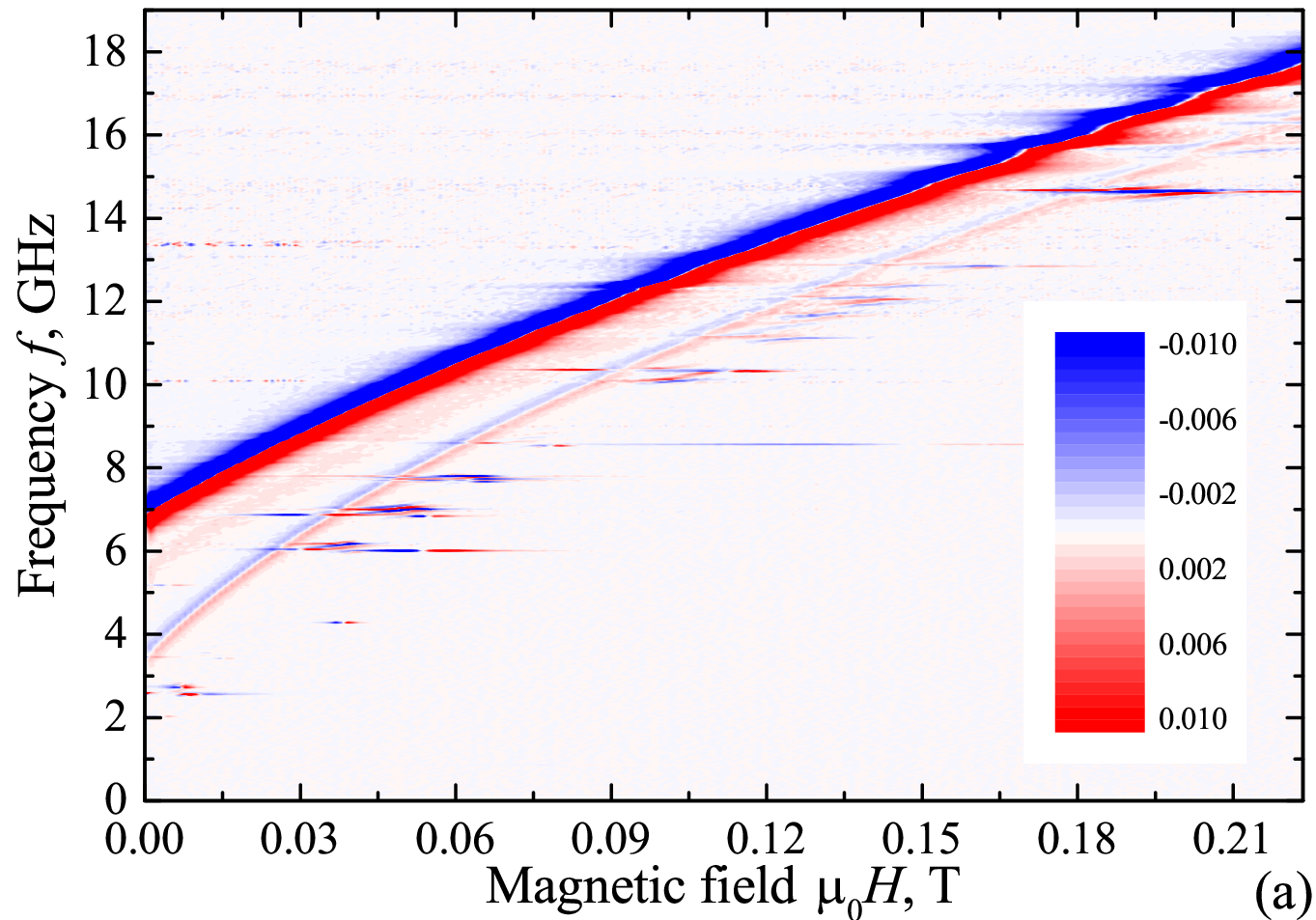
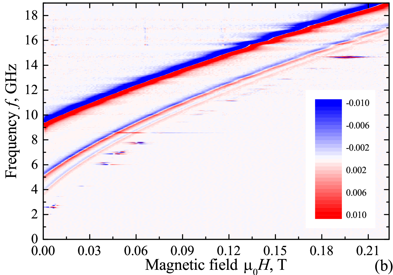
Figure 4a-c demonstrates the essence of the studied phenomenon: at temperatures below the critical temperature of Nb, , the transmission spectrum for SF2 sample consist of two spectral lines (Fig. 4a) and for SF3 sample consist of three spectral lines (Fig. 4b). At (Fig. 4c) FMR spectrum for both samples is reduced to a single spectral line, which obeys the conventional Kittel formula (Eq. 2, ). For both samples the fit of FMR curves at yields negligible anisotropy field mT, the effective magnetization T, which is close to typical values of the saturation magnetization of permalloy T, and no noticeable dependence of and on temperature. Temperature dependencies of FMR spectra for both samples yield superconducting critical temperatures K for SF2 sample and K for SF3 sample. The critical temperature of Nb layers is reduced in comparison to the bulk critical temperature of Nb K owing to the inverse proximity effect Aarts et al. 1997.
At (Fig. 4a,b) FMR spectrum shifts to higher frequencies and splits to spectral lines in accordance to the number of F-layers in the stack. The strongest line, the acoustic mode, is observed at the highest frequencies, while weaker lines at lower frequencies correspond to optic modes. Resonance lines were modelled with Eq. 6 using as the fitting parameter (see Fig. 4d,e). The optimum fit is obtained with nm for SF2 sample and nm for SF3 sample. The obtained is slightly higher than typical values in bulk Nb (about 80 nm) due to the inverse proximity effect Aarts et al. 1997; Silaev 2022b. A better fit could be obtained by considering a variation of in different S-layers. Thus, the provided theoretical description of the magnetization dynamics phenomenon in arbitrary S-F multilayers is verified.
Conclusion. Summarising, we report a study of magnetization dynamics in S-F multialyers. Theoretical considerations supported by experiments in a wide frequency, field, and temperature ranges show that the coupling between ferromagnetic layers via superconducting layers results in formation of antiferromagnetic interaction between F-layers with the strength that depends of thickness and superconducting properties of S-layers. This interaction between ferromagnetic layers is formed via superconducting currents and result in formation of acoustic and optic spectral branches. These results open wide prospects for application of S-F multialyers in magnonics and also bridges magnetization dynamics phenomena with various superconducting circuits Barnes et al. 2011; Mai et al. 2011; Golovchanskiy et al. 2017, hybrid devices Golovchanskiy et al. 2021a; Golovchanskiy et al. 2021b, and metamaterials Pimenov et al. 2005. Moreover, resonance properties of S-F multilayers by changing the superconducting state of S-layers opticallySilaev 2022b; Veshchunov et al. 2016; Magrini et al. 2019 or via electric currents.
Acknowledgements The authors acknowledge Dr M. Silaev for fruitful discussions. The research study was financially supported by the Russian Science Foundation (grant N 22-22-00314).
References
- Linder and Robinson (2015) J. Linder and J. W. A. Robinson, Superconducting spintronics, Nat. Phys. 11, 307 (2015).
- Dobrovolskiy et al. (2019) O. V. Dobrovolskiy, R. Sachser, T. Bracher, T. Fischer, V. V. Kruglyak, R. V. Vovk, V. A. Shklovskij, M. Huth, B. Hillebrands, and A. V. Chumak, Magnon-fluxon interaction in a ferromagnet/superconductor heterostructure, Nat. Phys. 15, 477 (2019).
- Dobrovolskiy et al. (2021) O. V. Dobrovolskiy, Q. Wang, D. Y. Vodolazov, B. Budinska, R. Sachser, A. V. Chumak, M. Huth, and A. I. Buzdin, arXiv , 2103.10156 (2021).
- Golovchanskiy et al. (2018a) I. A. Golovchanskiy, N. N. Abramov, V. S. Stolyarov, V. V. Bolginov, V. V. Ryazanov, A. A. Golubov, and A. V. Ustinov, Adv. Funct. Mater. 28, 1802375 (2018a).
- Golovchanskiy et al. (2018b) I. A. Golovchanskiy, N. N. Abramov, V. S. Stolyarov, V. V. Ryazanov, A. A. Golubov, and A. V. Ustinov, Modified dispersion law for spin waves coupled to a superconductor, J. Appl. Phys. 124, 233903 (2018b).
- Golovchanskiy et al. (2019) I. A. Golovchanskiy, N. N. Abramov, V. S. Stolyarov, P. S. Dzhumaev, O. V. Emelyanova, A. A. Golubov, V. V. Ryazanov, and A. V. Ustinov, Ferromagnet/superconductor hybrid magnonic metamaterials, Adv. Sci. 6, 1900435 (2019).
- Yu and Bauer (2022) T. Yu and G. E. W. Bauer, Phys. Rev. Lett. 129, 117201 (2022).
- Golovchanskiy et al. (2021a) I. A. Golovchanskiy, N. N. Abramov, V. S. Stolyarov, M. Weides, V. V. Ryazanov, A. A. Golubov, A. V. Ustinov, and M. Y. Kupriyanov, Science Advances 7, eabe8638 (2021a).
- Golovchanskiy et al. (2021b) I. A. Golovchanskiy, N. N. Abramov, V. S. Stolyarov, A. A. Golubov, M. Y. Kupriyanov, V. V. Ryazanov, and A. V. Ustinov, Physical Review Applied 16, 034029 (2021b).
- Silaev (2022a) M. A. Silaev, Ultrastrong magnon-photon coupling and entanglement in superconductor/ferromagnet nanostructures, arXiv:2211.00462 (2022a).
- Li et al. (2018) L.-L. Li, Y.-L. Zhao, X.-X. Zhang, and Y. Sun, Possible evidence for spin-transfer torque induced by spin-triplet supercurrents, Chin. Phys. Lett. 35, 077401 (2018).
- Jeon et al. (2019) K.-R. Jeon, C. Ciccarelli, H. Kurebayashi, L. F. Cohen, X. Montiel, M. Eschrig, T. Wagner, S. Komori, A. Srivastava, J. W. Robinson, and M. G. Blamire, Effect of meissner screening and trapped magnetic flux on magnetization dynamics in thick nb/ni80fe20/nb trilayers, Phys. Rev. Appl. 11, 014061 (2019).
- Golovchanskiy et al. (2020) I. A. Golovchanskiy, N. N. Abramov, V. S. Stolyarov, V. I. Chichkov, M. Silaev, I. V. Shchetinin, A. A. Golubov, V. V. Ryazanov, A. V. Ustinov, and M. Y. Kupriyanov, Phys. Rev. Appl. 14, 024086 (2020).
- Golovchanskiy et al. (2023) I. A. Golovchanskiy, N. N. Abramov, O. V. Emelyanova, I. V. Shchetinin, V. V. Ryazanov, A. A. Golubov, and V. S. Stolyarov, Physical Review Applied 19, 034025 (2023).
- Silaev (2022b) M. A. Silaev, Physical Review Applied 18, L061004 (2022b).
- Kostylev (2009) M. Kostylev, Journal of Applied Physics 106, 043903 (2009).
- Schmool and Barandiaran (1998) D. S. Schmool and J. M. Barandiaran, J. Phys.: Condens. Matter 10, 10679 (1998).
- Lindner and Baberschke (2003) J. Lindner and K. Baberschke, J. Phys.: Condens. Matter 15, R193 (2003).
- Rezende et al. (2019) S. M. Rezende, A. Azevedo, and R. L. Rodriguez-Suarez, Journal of Applied Physics 126, 151101 (2019).
- Golovchanskiy and Stolyarov (2022) I. A. Golovchanskiy and V. S. Stolyarov, Journal of Applied Physics 131, 053901 (2022).
- Golovchanskiy et al. (2022) I. A. Golovchanskiy et al., Phys. Rev. B 106, 024412 (2022).
- Holst et al. (1990) T. Holst, J. B. Hansen, N. Grnbech-Jensen, and J. A. Blackburn, Phys. Rev. B 42, 127 (1990).
- Sakai et al. (1993) S. Sakai, P. Bodin, and N. F. Pedersen, Journal of Applied Physics 73, 2411 (1993).
- Ustinov and Kohlstedt (1996) A. V. Ustinov and H. Kohlstedt, Phys. Rev. B 54, 6111 (1996).
- Neudecker et al. (2006) I. Neudecker, G. Woltersdorf, B. Heinrich, T. Okuno, G. Gubbiotti, and C. Back, Comparison of frequency, field, and time domain ferromagnetic resonance methods, J. Magn. Magn. Mat. 307, 148 (2006).
- Kalarickal et al. (2006) S. S. Kalarickal, P. Krivosik, M. Wu, C. E. Patton, M. L. Schneider, P. Kabos, T. J. Silva, and J. P. Nibarger, Ferromagnetic resonance linewidth in metallic thin films: Comparison of measurement methods, J. Appl. Phys. 99, 093909 (2006).
- Chen et al. (2007) Y.-C. Chen, D.-S. Hung, Y.-D. Yao, S.-F. Lee, H.-P. Ji, and C. Yu, Ferromagnetic resonance study of thickness-dependent magnetization precession in ni80fe20 films, J. Appl. Phys. 101, 09C104 (2007).
- Aarts et al. (1997) J. Aarts, J. M. E. Geers, E. Br’́uck, A. A. Golubov, and R. Coehoorn, Phys. Rev. B 56, 2779 (1997).
- Barnes et al. (2011) S. E. Barnes, M. Aprili, I. Petkovic, and S. Maekawa, Supercond. Sci. Technol. 24, 024020 (2011).
- Mai et al. (2011) S. Mai, E. Kandelaki, A. F. Volkov, and K. B. Efetov, Phys. Rev. B 84, 144519 (2011).
- Golovchanskiy et al. (2017) I. A. Golovchanskiy, N. N. Abramov, V. S. Stolyarov, O. V. Emelyanova, A. A. Golubov, A. V. Ustinov, and V. V. Ryazanov, Supercond. Sci. Technol. 30, 054005 (2017).
- Pimenov et al. (2005) A. Pimenov, A. Loidl, P. Przyslupski, and B. Dabrowski, Phys. Rev. Lett. 95, 247009 (2005).
- Veshchunov et al. (2016) I. S. Veshchunov, W. Magrini, S. V. Mironov, A. G. Godin, J.-B. Trebbia, A. I. Buzdin, P. Tamarat, and B. Lounis, Nat. Comm. 7, 12801 (2016).
- Magrini et al. (2019) W. Magrini, S. V. Mironov, A. Rochet, P. Tamarat, A. I. Buzdin, and B. Lounis, Appl. Phys. Lett. 114, 142601 (2019).