Automatically Annotating Indoor Images with CAD Models via RGB-D Scans
Abstract
We present an automatic method for annotating images of indoor scenes with the CAD models of the objects by relying on RGB-D scans. Through a visual evaluation by 3D experts, we show that our method retrieves annotations that are at least as accurate as manual annotations, and can thus be used as ground truth without the burden of manually annotating 3D data. We do this using an analysis-by-synthesis approach, which compares renderings of the CAD models with the captured scene. We introduce a ’cloning procedure’ that identifies objects that have the same geometry, to annotate these objects with the same CAD models. This allows us to obtain complete annotations for the ScanNet dataset and the recent ARKitScenes dataset. Source code and data will be available at https://github.com/stefan-ainetter/SCANnotate.
1 Introduction
3D scene understanding is one of the most challenging problems in computer vision. For indoor scenes, several datasets are already available including SceneNN [12], ScanNet [7], Matterport3D [4], and ARKitScenes [3]. However, with the exception of ScanNet for which some of the objects are annotated thanks to the Scan2CAD dataset [1], they do not provide annotations for the shapes of the objects. This is because 3D manual annotations of the shapes are particularly cumbersome to create, as one has to jointly estimate a good 6D pose and retrieve a well suitable CAD model for each object. The Pix3D dataset [20] is also annotated with CAD models. However, it is made of single-object images, without partial occlusions, which facilitates the annotations but is also likely to bias training and evaluation.

Using synthetic images for training is another option, however generating realistic virtual 3D scenes also has a high financial cost, both in terms of creation and rendering [19]. Moreover, testing should still be done on real images.
In this paper, we report our work on how to automatically retrieve good CAD models for objects in a scene captured by a moving RGB-D camera. Figure 1 shows the CAD models we retrieved for one scene from ScanNet and one scene from ARKitScenes. Visual evaluation by experts in the domain of computer vision demonstrated that our CAD models are often as good or better than the manual annotations from Scan2CAD, while they are obtained automatically. We thus see our method as a tool that automatically generates annotations, which can then be used to train supervised methods for fast inference. On average, our non-optimized implementation takes approximately minutes per scene using two NVidia GeForce RTX 2080 Ti graphics cards, compared to Scan2CAD human annotations that take minutes per scene [1], while being completely automated.
Our method is not based on learning and thus does not require registered 3D models for training. Instead, we use as input 3D oriented bounding boxes or instance segmentation for the objects: These annotations are much simpler than CAD model fitting and they are in fact available for the main existing datasets as detailed in Table 1. Because we also adjust the bounding boxes anyway, these boxes do not have to be particularly accurate. To find a suitable CAD model, we sequentially replace the target object with one of the 3D models from the ShapeNet database [5]. By following an analysis-by-synthesis approach, we select the best CAD model by comparing depth renderings to the captured depth maps while adjusting the 9D pose and scale of the CAD models. As Figure 1 also shows, by relying on depth data to select and register the CAD models, the CAD models we retrieve are not only well located in 3D but also reproject well in the images of the RGB-D scans.
In man-made environments, it often happens that multiple objects have the same shape, such as the chairs around the table for the ARKitScenes example in Figure 1. However, independently searching for the CAD models of these multiple instances is likely to yield different 3D models. To exploit the high-level knowledge that several objects tend to have the same shape, we cluster the CAD models retrieved after an independent search based on the similarity of their shapes. We then perform a joint retrieval, looking for the same CAD model for all the objects in the cluster. This way, we can exploit more information from the depth maps to retrieve a better CAD model: For example, if we found that two chairs share the same shape, but the top of the first chair and the bottom of the second chair are not visible in the RGB-D scan, we can still recover a correct CAD model for the two chairs.

We did not find any previous method that attempted to solve the same problem as us. Note that the Scan2CAD method from [1] (not to be confused with the Scan2CAD annotations) does retrieve CAD models for ScanNet, but from a very small pool created for benchmarking the proposed method: The size of the pool is taken to be equal to the number of objects in the scene, i.e., in a range of 5 to 30 CAD models selected from the ShapeNet dataset. It is also designed to contain the ground truth models. [1] shows an experiment with more CAD models (400), it is however only a qualitative result. By contrast, we search through the entire set of CAD models for the target object class. For example, we consider the 8437 CAD Tables models and the 6779 CAD Chairs models in ShapeNet.
To the best of our knowledge, our method is thus the first one to achieve ground-truth-like CAD model retrieval and alignment. Overall, we make the following contributions:
- 1.
We introduce a fully-automatic method for CAD model retrieval and alignment that results in a fine alignment between the images and the reprojected CAD models.
- 2.
We show how to identify the objects that share the same geometry, and retrieve a common CAD model for these objects—we call this procedure ’cloning’.
- 3.
We show that the quality of our results is comparable or better than human annotations.
- 4.
- 5.
Our method can be seen as a tool to automatically annotate images with CAD models and poses for the objects in the images, and we will make our annotations for the ScanNet scenes and for ARKitScenes publicly available.
| Dataset | #scans |
|
| ||||
|---|---|---|---|---|---|---|---|
| SceneNN [12] | 100 | OBB, Inst.Seg. | ✗ | ||||
| ScanNet [7] | 1513 | Inst.Seg. | Scan2CAD [1] (*) | ||||
| Matterport3D [4] | 2056 | Inst.Seg. | ✗ | ||||
| ARKitScenes [3] | 5047 | OBB | ✗ |
2 Related Work
We focus our discussion on methods for CAD model retrieval in 3D scans.
2.1 Using Object Representations
A popular approach for CAD model retrieval is to represent the objects using embeddings. More exactly, it is possible to learn a representation for point clouds of objects, and a representation for CAD models in the same embedding space [1, 2, 6, 8, 10].
This approach allows for fast retrieval: The embedding space can be learned so that it can be used by efficient methods such as hashing for nearest neighbor search. However, annotated data is required to learn the embeddings. In our case, we are interested in an offline method; computation time is thus not critical while accuracy is much more important. We thus consider an exhaustive search and a geometric criterion to evaluate how much a CAD model corresponds to the 3D scan. This is a safer approach than relying on the similarity between implicit embeddings.
2.2 [Semi-]Manual Retrieval
A few datasets already exist for evaluating deep learning approaches for CAD model retrieval.
The authors of Pix3D [20] crawled web images to find images of objects from the IKEA object catalogue that were later verified by Amazon Mechanical Turk workers. To simplify the 3D annotation procedure, they also kept only images without occlusions. Then, human annotators would manually select keypoint correspondences between each input image and the 3D model manually selected for the image. Using PnP and refinement, it is then possible to determine the 6D object pose. Similarly, for creating the Scan2CAD dataset [1], human annotators were asked for each object to first, find the corresponding model in the ShapeNet dataset [5] for the object within a bounding box and, then, click on correspondences between the 3D model and the point cloud to obtain the alignment. Manually annotating 3D scans is however a heavy burden: Not all objects are annotated in Scan2CAD and ARKitScenes is not annotated with CAD models yet. We thus believe that our approach is very useful and scales better to large datasets.
Using synthetic images for training is also an attractive option, as the 3D annotations come then free. However, creating the 3D content and rendering it has also a high cost. For example, [19] reports a cost of $57K to create Hypersim, a dataset of about 71’000 synthetic images for scene creation + image rendering, and a period of 2.4 years of wall-clock time on a large compute node.
2.3 Analysis-by-Synthesis Approaches
Analysis-by-synthesis in not a new concept in computer vision [21, 14, 11, 13]. Some methods combine analysis-by-synthesis with learning [16, 17] but others, like us, do not [9, 22, 10]. In particular, the recent [10] is probably the closest work to us. However, [10] focuses on retrieving arrangements of objects that explain the point clouds overall and not on accuracy. In our case, we exploit the existing 3D bounding box annotations as our goal is to provide accurate annotations. We perform an exhaustive search on the CAD models while [10] relies on embeddings. We also provide the annotations we retrieved.
3 Method
For each scene, we have an RGB-D scan of registered RGB images and depth maps, as well as a 3D mesh reconstructed from the scan. Our aim is to find for each object in the scene the most similar CAD model within the ShapeNet dataset, along with the corresponding pose as a 9-DoF transformation , made of a 3D translation, 3D rotation, and scale along the 3 axes. We only consider target objects that have either object box annotations or semantic instance segmentation available as supervision. Note that this kind of supervision is relatively easy to generate (and often already available as ground truth in public 3D indoor scene datasets, as seen in Table 1) compared to CAD model retrieval annotation, which requires the annotator to manually search a suitable CAD model from a large database.
An overview of our method is shown in Figure 2. It first performs CAD model retrieval, by sequentially replacing the target object in the scene with all available CAD models from the same object category. After replacing the object, we render the modified scene to generate observations corresponding to the selected CAD model. By doing this for all CAD models, we exhaustively search for the most perceptually similar model, according to the observations. After finding initial CAD models for each target object, our method focuses on retrieving geometrically similar CAD models for geometrically similar target objects in the scene. Finally, we perform differentiable object alignment to optimize the 9-DoF pose of each CAD model, taking into account the top-k retrievals for alignment-aware object retrieval. We describe each component of our CAD model retrieval pipeline in detail below.
3.1 Data Preprocessing
We use the 3D oriented object box as initialization for position, scale and orientation of the target object, whereas 3D semantic instance segmentation is used as geometrical information to replace the target object in the scene with the CAD models. We use either the 3D bounding box information or the instance segmentation provided by the dataset, which allows us to calculate an approximation for the other missing part. We select a number of frames from all frames of the RGB-D scan, by selecting the frames where the target object is in the field of view according to its 3D bounding box and then regularly sample these frames. We also use the provided class label from each target object to identify the corresponding ShapeNet category.
3.2 Initial CAD Model Retrieval

We sequentially replace the target object in the input scene with each ShapeNet CAD model from the corresponding class category. Figure 3 illustrates this replacement procedure: We use the 3D semantic instance segmentation to remove all 3D points in the scene which are part of the target object . Then, we use the initial 3D scale, position and orientation extracted from the 3D oriented object bounding box to calculate an initial transformation which enables us to directly insert the CAD model at the position of the target object .
Our method follows an analysis-by-synthesis approach to evaluate how well a CAD model corresponds to a real object. Such an approach is important to obtain a fine alignment of the reprojected CAD models with the input images. To measure quantitatively how well a CAD model fits a real object, we introduce a simple objective function that mainly compares observed depth data and the depth of the CAD model. This objective function does not require any training, and thus does not require any annotation.
3.2.1 Depth Matching Term
The main terms of our objective function compare the depth maps for the CAD model and the 3D scene mesh after replacement with the observed depth maps.
We noticed that with ScanNet, it is possible to generate a depth map of the scene that is better than the captured depth map by rendering the mesh, as seen in Figure 4. For ARKitScenes, the scene meshes currently available are pretty noisy, and it is often better to consider the captured depth map than the rendered mesh. We therefore use a linear combination of the two possible comparisons:
| (1) | ||||
where the sum is over the selected frames of the RGB-D scan for the specific target object. Depth maps , , and are respectively the depth map rendered from the CAD model and the 3D scene mesh after replacement, the depth map rendered from the scene mesh, and the captured depth map for frame . and denote the valid pixel maps for the depth maps and , respectively. We use the L1 norm to compare the depth maps and normalize the norms by the numbers of valid pixels and . Weights and can be adapted to the dataset, depending on the quality of the captured depth maps and the 3D mesh.
Examples for , , and are shown in Figure 4. Rendering a depth map is computed once per target object, whereas has to be computed for each CAD model that comes into consideration. However, this can be done efficiently by rendering the ’background’ scene once, and then rendering each CAD model independently and fusing the results.


3.2.2 Additional Terms and
During our experiments, we noticed that in some specific cases, the term introduced above is not sufficient to obtain optimal CAD model retrieval. For example, the term introduced below proved to be decisive when the selection of frames does not cover the whole target object, whereas the term provide strong information about details of the object’s shape.
For , we consider the Intersection-over-Union between the silhouettes of the real object and of the CAD model:
| (2) |
where and are the rendered object masks for the real object and a possible CAD model, respectively, for frame . Examples of and are shown in Figure 4.
Additionally, we use the (one-way) Chamfer distance from the points on the real object to the CAD model:
| (3) |
where is the point cloud for the real object as identified using the bounding box and/or the segmentation as explained in Section 3.1 and is a set of 3D points sampled on the CAD model.
3.2.3 Objective Function
Our objective function can now be defined as
| (4) |
where and are weights. We compute this objective function for each CAD model in ShapeNet that matches the class label of the current target object.
3.3 CAD Model Cloning
Given a 3D scene such as the one shown in Figure 5 for ScanNet, a human annotator will recognize that several objects in the scene share the same geometry. However, this behaviour is not guaranteed with our per-object predictions for CAD model retrieval. To solve this issue, we add a simple yet effective method to identify objects that share their shapes and to retrieve an appropriate CAD model for all the identified objects.
We first cluster the CAD models retrieved independently for each object by the method described in Section 3.2. We use a bottom-up clustering based on the pair-wise Chamfer distance between the CAD models. More precisely, for each pair of retrieved CAD models, we first calculate their symmetric Chamfer distance. Then, we iteratively go through all object pairs from lowest to highest Chamfer distance and perform one of the following steps if their Chamfer distance is below a threshold (we use in practice): (a) If none of the two objects is already part of a cluster, a new cluster with these two objects is created. (b) If one of the objects is already part of a cluster, and the other one is not assigned to a cluster yet, it is added to the same cluster. (c) If both objects are already assigned to different clusters, these clusters are merged.
Then, for each cluster with more than one object, we look for a common CAD model that minimizes the sum of the objective functions from Eq. (4) over all the objects in the cluster, when replacing every object by the CAD model. Figure 5 shows an example for our CAD model clustering and cloning.

3.4 Differentiable Pose Refinement
Once we found a CAD model for an object, possibly by the cloning procedure explained above, we refine its 9-DoF pose , i.e., its scale, position, and orientation to fit the depth observations better. We initialize its pose using the 3D bounding box that is either part of the dataset as ground truth, or calculated during our preprocessing step. To do this, we minimize the objective function of Eq. (4) over the 9 pose parameters in using the differentiable rendering pipeline of [18] and the Adam optimizer [15].
4 Evaluation and Experiments
To evaluate the performance of our method, we considered the popular ScanNet dataset and the more recent ARKitScenes dataset. We asked computer vision experts to conduct a visual evaluation on ScanNet to compare our automatically retrieved annotations with the annotations provided by Scan2CAD, to evaluate if our method can provide ground truth annotations with comparable quality to manual annotations. We then conduct a visual inspection of the results on ScanNet, and additionally provide qualitative results on the ARKitScenes dataset.
4.1 Evaluation using Scan2CAD
To evaluate the performance of our proposed method, we conducted a visual evaluation by asking 3D experts to compare our results to Scan2CAD, which provides ground truth for CAD model retrieval and alignment for ScanNet. We perform this evaluation on the ScanNet validation set, which consists of indoor scenes. To ensure fair comparison, we use the initial 3D bounding boxes from Scan2CAD.
Implementation details.
We set the weights in Eqs. (1) and (4) to , and . To compute the Chamfer distance in , we uniformly sample points from the surface mesh of each CAD model. For the CAD models that were not substituted by our cloning method, we first retrieve the top-3 best CAD models, perform pose refinement for each 3 of them, and keep the one with the lowest objective function value. For the CAD models issued by the cloning procedure, we perform the pose refinement with the common CAD model.
4.1.1 Quantitative Comparison
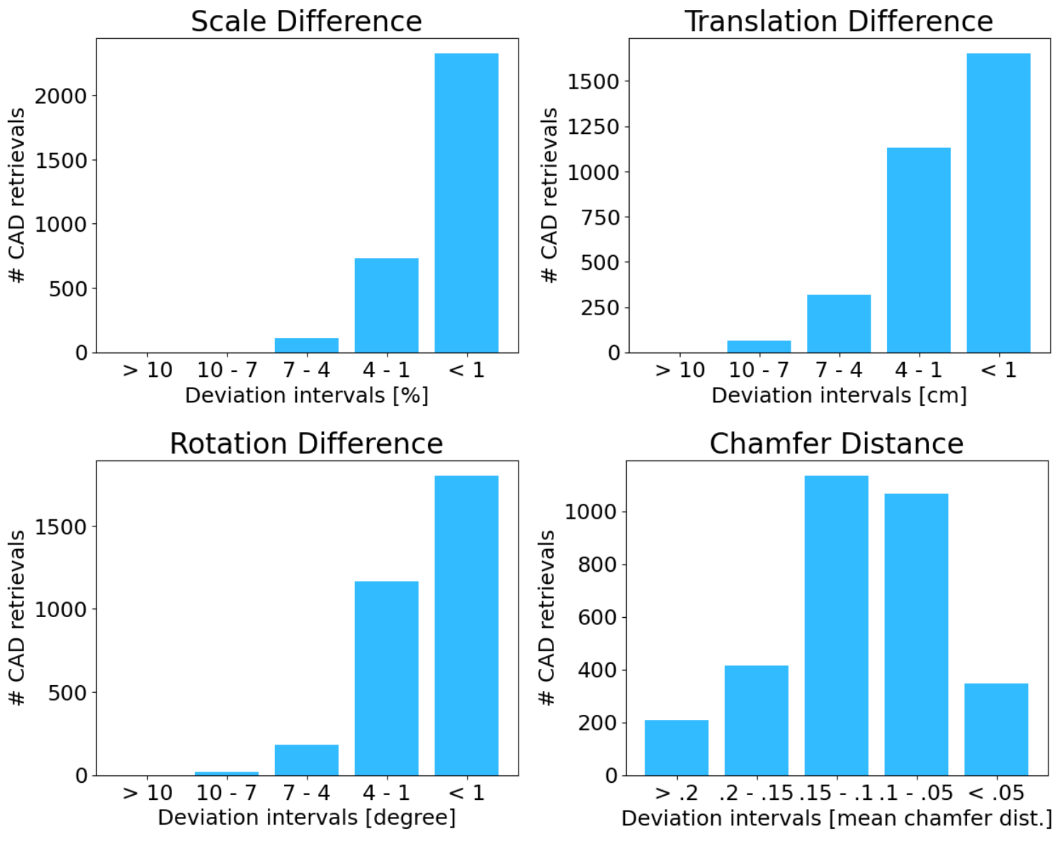
As proposed in the Scan2CAD paper [1], CAD retrieval and alignment can be evaluated in terms of translation, rotation, and scale error. Additionally, we argue that shape difference is also a important criterion. For each target object in the validation set, we compare our results with the corresponding Scan2CAD ground truth, by calculating the difference of rotation, translation, scale and shape.
Figure 6 shows the deviation of our results compared to the Scan2CAD annotations. As one can see, the majority of our predicted CAD model retrievals do have a very small difference compared to ground truth for all criteria, which already indicates the high quality of our results.
4.1.2 Visual Evaluation by Experts

The quantitative comparison with the Scan2CAD annotations provided above gives the deviation with respect to these annotations, however it does not tell what these differences mean in terms of overall quality, and which annotations are better—or if they are equivalent.
To answer these questions, we conducted a visual evaluation by computer vision experts on the 165 objects with the largest deviation from the Scan2CAD annotations. To keep the comparison simple, we generated pairs of images where we reprojected the CAD models provided by Scan2CAD and the CAD models retrieved by our method. Figure 7 shows an example of such a pair of images. Such reprojections were easier to interpret for the subjects than a 3D scene, but to make sure that the poses of the CAD models were also evaluated correctly and not just their reprojections, we used multiple views of the same scenes.
The experts were not told which method was used and images were shuffled so that our method appeared 50% of the time in the top image and 50% of the time in the bottom image, to prevent the subjects to be biased towards one of the two sides or methods. For each pair of images, the experts were asked to answer the question: “Do the reprojections in the top image look better, worse, or similar to the reprojection in the bottom image?” As this question requires some domain expertise, we had to restrict the subjects to PhD students working on computer vision and computer graphics. In total, 9 experts participated to this study.
The results are shown in Figure 7: For 43.7% of all the shown pairs, the subjects prefer the CAD models and poses from Scan2CAD, for 24.5%, they prefer the CAD models and poses retrieved by our method, and for the 31.8% left, they found the two sources were similar. This validates that our method can be used in place of human annotations, as it produces annotations of similar or better quality on average.
4.1.3 Fine-grain Evaluation
To get a better understanding of how our automatic annotations compare to the manual ones, we visualized the objects with the highest deviation for each criterion considered in Section 4.1.1 (translation, rotation, scale, shape) and evaluated the geometry and alignment through visual inspection. Table 2 shows the results. For the majority of these objects, the overall quality of geometric shape and alignment is equal or better than the annotations from the Scan2CAD dataset. Figure 8 shows examples for objects with large differences for different criteria.
| Annotations | ||||
|---|---|---|---|---|
| Scan2CAD | Annotations | Annotations | by our method | |
| annotations | by our method | have similar | are similar | |
| Criterion | are better | are better | quality | or better |
| Translation | 10 | 7 | 33 | 40 |
| Rotation | 12 | 10 | 28 | 38 |
| Scale | 12 | 7 | 31 | 38 |
| Shape | 20 | 8 | 22 | 30 |

4.1.4 Additional Annotations for ScanNet
Figure 9 shows a comparison of results for full scene CAD retrieval by our method with Scan2CAD: As already mentioned, the Scan2CAD dataset does not provide annotations for all the objects. About one third of the objects of standard classes ( objects for the scenes in the ScanNet validation set) are not labeled with a CAD model nor pose, but since our method is automated, we were able to retrieve a CAD model and pose for all these objects. This represents on average additional objects per scene, and about 37% more retrieved objects than in the Scan2CAD annotations.

4.2 Results on the ARKitScenes Dataset
To show the generalization ability of our method, we also ran our method on the recently published ARKitScenes dataset. This dataset consists of RGB-D scans of indoor scenes, and provides 3D oriented bounding boxes as ground-truth annotations. Note that there are no CAD models provided as ground truth for this dataset.
Implementation details.
The quality of the sensor data for this dataset is significantly better compared to ScanNet, and the depth maps provided by ARKitScenes are much better. However, the quality of the 3D scene meshes provided by ARKitScenes is still significantly lower than the ones available for ScanNet. Therefore, we adjusted the weight parameters to , , , .
Retrieved annotations.
Figure 10 shows examples of the CAD models and their poses retrieved by our method. The advantage of our cloning procedure is also clearly visible.

5 Conclusion
We presented a method to retrieve CAD models for objects in 3D scans and their poses that have similar quality as manual annotations.
The CAD models reproject well on the images used to capture the scans. We thus hope that our results can be used for 3D scene understanding from single images. We will make available the annotations we retrieved for the ScanNet and ARKitScenes datasets.
Acknowledgment. This work was supported by the Christian Doppler Laboratory for Semantic 3D Computer Vision, funded in part by Qualcomm Inc.
References
- [1] Armen Avetisyan, Manuel Dahnert, Angela Dai, Manolis Savva, Angel X. Chang, and Matthias Nießner. Scan2cad: Learning CAD Model Alignment in RGB-D Scans. In Conference on Computer Vision and Pattern Recognition, 2019.
- [2] Armen Avetisyan, Angela Dai, and Matthias Nießner. End-To-End CAD Model Retrieval and 9dof Alignment in 3D Scans. In International Conference on Computer Vision, 2019.
- [3] Gilad Baruch, Zhuoyuan Chen, Afshin Dehghan, Tal Dimry, Yuri Feigin, Peter Fu, Thomas Gebauer, Brandon Joffe, Daniel Kurz, Arik Schwartz, and Elad Shulman. ARKitScenes - A Diverse Real-World Dataset for 3D Indoor Scene Understanding Using Mobile RGB-D Data. In Thirty-fifth Conference on Neural Information Processing Systems Datasets and Benchmarks Track (Round 1), 2021.
- [4] Angel Chang, Angela Dai, Thomas Funkhouser, Maciej Halber, Matthias Niessner, Manolis Savva, Shuran Song, Andy Zeng, and Yinda Zhang. Matterport3D: Learning from RGB-D Data in Indoor Environments. In International Conference on 3D Vision, 2017.
- [5] Angel X. Chang, Thomas Funkhouser, Leonidas Guibas, Pat Hanrahan, Qixing Huang, Zimo Li, Silvio Savarese, Manolis Savva, Shuran Song, Hao Su, and Others. ShapeNet: An Information-Rich 3D Model Repository. In arXiv Preprint, 2015.
- [6] Manuel Dahnert, Angela Dai, Leonidas Guibas, and Matthias Nießner. Joint Embedding of 3D Scan and CAD Objects. In International Conference on Computer Vision, 2019.
- [7] Angela Dai, Angel X. Chang, Manolis Savva, Maciej Halber, Thomas Funkhouser, and Matthias Nießner. ScanNet: Richly-Annotated 3D Reconstructions of Indoor Scenes. In Conference on Computer Vision and Pattern Recognition, 2017.
- [8] Alexander Grabner, Peter M. Roth, and Vincent Lepetit. 3D Pose Estimation and 3D Model Retrieval for Objects in the Wild. In Conference on Computer Vision and Pattern Recognition, 2018.
- [9] Abhinav Gupta, Martial Hebert, Takeo Kanade, and David Blei. Estimating Spatial Layout of Rooms using Volumetric Reasoning about Objects and Surfaces. Advances in Neural Information Processing Systems, 2010.
- [10] Shreyas Hampali, Sinisa Stekovic, Sayan Deb Sarkar, Chetan S. Kumar, Friedrich Fraundorfer, and Vincent Lepetit. Monte Carlo Scene Search for 3D Scene Understanding. In Conference on Computer Vision and Pattern Recognition, 2021.
- [11] Mohsen Hejrati and Deva Ramanan. Analysis by Synthesis: 3D Object Recognition by Object Reconstruction. In Conference on Computer Vision and Pattern Recognition, 2014.
- [12] Binh-Son Hua, Quang-Hieu Pham, Duc Thanh Nguyen, Minh-Khoi Tran, Lap-Fai Yu, and Sai-Kit Yeung. SceneNN: A Scene Meshes Dataset with Annotations. In International Conference on 3D Vision, 2016.
- [13] Siyuan Huang, Siyuan Qi, Yixin Zhu, Yinxue Xiao, Yuanlu Xu, and Song-Chun Zhu. Holistic 3D Scene Parsing and Reconstruction from a Single RGB Image. In European Conference on Computer Vision, 2018.
- [14] Phillip Isola and Ce Liu. Scene Collaging: Analysis and Synthesis of Natural Images with Semantic Layers. In International Conference on Computer Vision, pages 3048–3055, 2013.
- [15] Diederik P. Kingma and Jimmy Ba. Adam: A Method for Stochastic Optimization. In International Conference for Learning Representations, 2015.
- [16] Abhijit Kundu, Yin Li, and James M. Rehg. 3D-RCNN: Instance-Level 3D Object Reconstruction via Render-and-Compare. In Conference on Computer Vision and Pattern Recognition, 2018.
- [17] Yi Li, Gu Wang, Xiangyang Ji, Yu Xiang, and Dieter Fox. DeepIM: Deep Iterative Matching for 6D Pose Estimation. In European Conference on Computer Vision, 2018.
- [18] Nikhila Ravi, Jeremy Reizenstein, David Novotny, Taylor Gordon, Wan-Yen Lo, Justin Johnson, and Georgia Gkioxari. Accelerating 3D Deep Learning with PyTorch3D. In arXiv Preprint, 2020.
- [19] Mike Roberts and Nathan Paczan. Hypersim: A Photorealistic Synthetic Dataset for Holistic Indoor Scene Understanding. In arXiv Preprint, 2020.
- [20] Xingyuan Sun, Jiajun Wu, Xiuming Zhang, Zhoutong Zhang, Chengkai Zhang, Tianfan Xue, Joshua B. Tenenbaum, and William T. Freeman. Pix3D: Dataset and Methods for Single-Image 3D Shape Modeling. In Conference on Computer Vision and Pattern Recognition, 2018.
- [21] Alan Yuille and Daniel Kersten. Vision as Bayesian Inference: Analysis-by-Synthesis? Trends in Cognitive Science, 2006.
- [22] Chuhang Zou, Ruiqi Guo, Zhizhong Li, and Derek Hoiem. Complete 3D Scene Parsing from an RGBD Image. International Journal of Computer Vision, 2019.