Real-World Chaos-Based Cryptography Using Synchronised Chua Chaotic Circuits
Thanks: Funded by DFG, under Projects 440182124 and 439892735 of SPP 2253, and by BMBF under Joint Project 16KISK034 for the 6G-RIC.
Abstract
This work presents the hardware demonstrator of a secure encryption system based on synchronised Chua chaotic circuits. In particular, the presented encryption system comprises two Chua circuits that are synchronised using a dedicated bidirectional synchronisation line. One of them forms part of the transmitter, while the other of the receiver. Both circuits are tuned to operate in a chaotic mode. The output (chaotic) signal of the first circuit (transmitter) is digitised and then combined with the message to be encrypted, through an XOR gate. The second Chua circuit (receiver) is used for the decryption; the output chaotic signal of this circuit is similarly digitised and combined with the encrypted message to retrieve the original message. Our hardware demonstrator proves that this method can be used in order to provide extremely lightweight real-world, chaos-based cryptographic solutions.
Index Terms:
chaos, Chua circuit, stream encryption, securityIntroduction
The rapid increase in the number of electronic devices in everyday use leads to an unlimited growth of vulnerable communication that must be protected from possible attacks. Having in focus the growing Internet of Things ecosystem, as well as edge computing, secure data transmission appears as a very important part. One of the strongest tools for mitigating attacks on electronic communications, is cryptography.
In our work, we focus on securing the transmitted information through symmetric stream cryptography that is based on the chaotic signal produced by two synchronised Chua chaotic circuits [1], one of which forms part of the transmitter and the other of the receiver. The produced chaotic signal acts as a random number stream that is shared by the synchronised chaotic circuits. Thus, the message can be encrypted at the transmitter by being XORed with a digitised form of the aforementioned chaotic signal, and decrypted at the receiver by XORing the encrypted message stream with the digitised form of the same chaotic signal.
Description of the Hardware Demonstrator
A simplified architecture of the proposed synchronized chaotic encryption-decryption system is shown in Figure 1. A proof-of-concept circuit of this system has been designed and appears in Figure 2, which demonstrates the full circuitry. The relevant characteristics and values of the components used for implementing the circuits are listed in Table I.

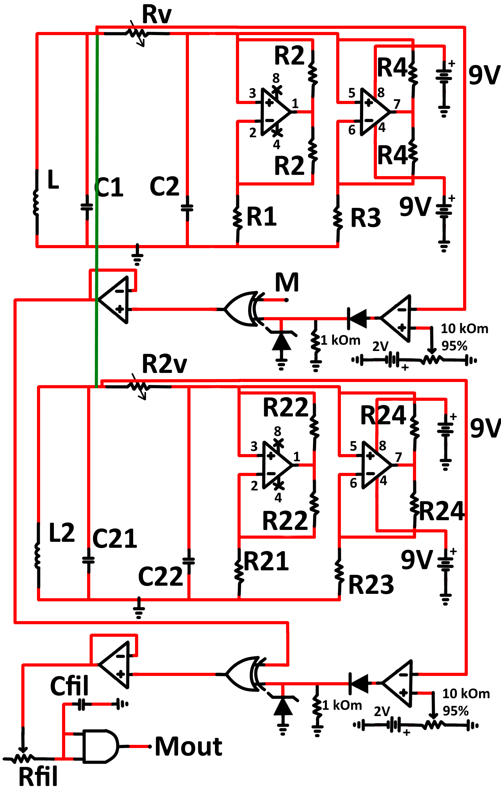
The Chua circuits that we are using, are based on the ones examined by Kennedy [2]. In our approach, two channels are utilized, one for achieving synchronisation and another for transmitting information. The signal produced by the chaotic circuits is digitised and processed according to the method described in [3, 4]. After being processed, this signal is used to encrypt a message, by performing an XOR operation. In order to perform a successful decoding, the transmitter and receiver are synchronised using a dedicated bidirectional synchronisation line.
In our demo, the message is generated by a wave generator with the following parameters: frequency kHz, amplitude Vpp, offset V, phase , and duty cycle . The encrypted message (coming from the XOR) is transmitted to the receiver, which in its turn decodes it, using the XOR operation and its own synchronized chaotic signal, which is processed in a similar way as the chaotic signal of the transmitter. The decrypted message is then cleared by an RC low-pass filter. A real-world implementation of the system is shown in Figure 3.
| Component | Characteristics |
|---|---|
| Inductors | 18 mH, 10% tolerance |
| Capacitors | 100 nF, 5% tolerance |
| Capacitors | 10 nF, 5% tolerance |
| Variable resistors | 1555 |
| Resistors | 3.3 k, 5% tolerance |
| Resistors | 22 k, 5% tolerance |
| Resistors | 2.2 k, 5% tolerance |
| Resistors | 220 , 5% tolerance |
| OpAmps | TL082ACP, TL081DIP |
| Batteries | 2 V, 9 V |
| Capacitor | 7 nF, 5% tolerance |
| Resistor | 1 k, 5% tolerance |

In Figure 4a, the attractor produced by the transmitter’s circuit is illustrated. The chaotic mode of operation of the Chua circuit is evident. The transmitter and the receiver are reliably chaotic-synchronised, as demonstrated by the synchronization phase portrait appearing in Figure 4b, based on the voltages on capacitors C1 and C21. The synchronization quality (perfect in this case) is responsible for the system’s ability to provide efficient decryption. Finally, Figure 5 presents the initial message (magenta) encrypted in the transmitter, the encrypted message (blue) that is transmitted, and the decrypted message (yellow) at the receiver’s output. It is rather evident that the initial message and the decrypted one match.
The circuitry shown in Figure 3, together with the relevant power supply (batteries), oscilloscope, and wave generator, form the main part of our hardware demonstrator setup.


Conclusion
Concluding, one may support that our hardware demonstrator proves that the proposed encryption-decryption system, which is based on two synchronized Chua chaotic circuits, can provide an efficient, lightweight, and practical solution for real-world cryptographic applications.
References
- [1] N. A. Anagnostopoulos, “Stability and robustness of three non-linear cryptographic systems under external noise conditions,” B.Sc. Thesis, Aristotle University, Thessaloniki, Greece, 2010.
- [2] M. P. Kennedy, “Robust OP amp realization of Chua’s circuit,” Frequenz, vol. 46, no. 3-4, pp. 66–80, 1992.
- [3] A. Miliou, S. Stavrinides, A. Valaristos, and A. Anagnostopoulos, “Nonlinear electronic circuit, Part II: synchronization in a chaotic MODEM scheme,” Nonlinear Analysis: Theory, Methods & Applications, vol. 71, 12 2009.
- [4] S. Stavrinides, A. Anagnostopoulos, A. Miliou, A. Valaristos, L. Magafas, K. Kosmatopoulos, and S. Papaioannou, “Digital chaotic synchronized communication system,” Journal of Engineering Science and Technology Review, vol. 2, 06 2009.