A Platform for Braiding Majorana Modes with Magnetic SkyrmionsPreprint: APS/123-QED
Abstract
After a decade of intense theoretical and experimental efforts, demonstrating braiding of Majorana modes remains an unsolved problem in condensed matter physics due to platform specific challenges. In this work, we propose topological superconductor – magnetic multilayer heterostructures with on-chip microwave cavity readout as a novel platform for initializing, braiding and reading out Majorana modes. Stray fields from a skyrmion in the magnetic layers can nucleate a vortex in the topological superconducting layer. Such a vortex is known to host Majorana bound states at its core. Through analytical calculations within London and Thiele formalisms, and through micromagnetic simulations, we show that our nucleation and braiding scheme can be effectively realized with a variety of existing options for magnetic and superconducting layers. Further, we show that the coupling of the Majorana bound states to electric field of a resonator leads to an experimentally observable parity-dependent dispersive shift of the resonator frequency. Our work paves the way for realizing Majorana braiding in the near future.
I Introduction
Demonstration of non-abelian exchange statistics is one of the most active areas of condensed matter research and yet experimental realization of braiding of Majorana modes remains elusive Nayak et al. 2008; Zhang et al. 2019. Most efforts so far have been focused on superconductor/semiconductor nanowire hybrids, where Majorana bound states (MBS) are expected to form at the ends of a wire or at boundaries between topologically trivial and non-trivial regions Rokhinson et al. 2012; Deng et al. 2012; Mourik et al. 2012; Lutchyn et al. 2018. Recently, it became clear that abrupt interfaces may also host topologically trivial Andreev states with experimental signatures similar to MBS Pan et al. 2020; Yu et al. 2021, which makes demonstrating braiding in nanowire-based platforms challenging. Phase-controlled long Josephson junctions (JJ) open much wider phase space to realize MBS with a promise to solve some problems of the nanowire platform, such as enabling zero-field operation to avoid detrimental flux focusing for in-plane fields Pientka et al. 2017; Ren et al. 2019. However, MBSs in long JJs suffer from the same problems as in the original Fu-Kane proposal for topological insulator/superconductor JJs, such as poor control of flux motion along the junction and presence of sharp interfaces in the vicinity of MBS-carrying vortices which may host Andreev states and trap quasiparticles. For instance, MBS spectroscopy in both HgTe and InAs-based JJs shows a soft gap Fornieri et al. 2019, despite a hard SC gap in an underlying InAs/Al heterostructure.

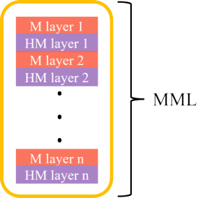
In the search for alternate platforms to realize Majorana braiding, spectroscopic signatures of MBS have been recently reported in STM studies of vortex cores in iron-based topological superconductors (TSC) Wang et al. 2018a. Notably, a hard gap surrounding the zero-bias peak at a relatively high temperature of K, and a K separation gap from trivial Caroli-de Gennes-Matricon (CdGM) states were observed Chen et al. 2020; Chen et al. 2018. Moreover, vortices in a TSC can be field-coupled to a skyrmion in an electrically-separated magnetic multilayer (MML) Dahir et al. 2019; Petrović et al. 2021, which can be used to manipulate the vortex. This allows for physical separation of the manipulation layer from the layer wherein MBS reside, eliminating the problem of abrupt interfaces faced by nanowire hybrids and JJs. Finally, recent advances in the field of spintronics provide a flexible toolbox to design MML in which skyrmions of various sizes can be stabilized in zero external magnetic field and at low temperatures Petrović et al. 2021; Büttner et al. 2018; Dupé et al. 2016. Under the right conditions, stray fields from these skyrmions alone can nucleate vortices in the adjacent superconducting layer. In this paper, we propose TSC–MML heterostructures hosting skyrmion-vortex pairs (SVP) as a viable platform to realize Majorana braiding. By patterning the MML into a track and by driving skyrmions in the MML with local spin-orbit torques (SOT), we show that the SVPs can be effectively moved along the track, thereby facilitating braiding of MBS bound to vortices.
The notion of coupling skyrmions (Sk) and superconducting vortices (Vx) through magnetic fields has been studied before Dahir et al. 2019; Baumard et al. 2019; Zhou et al. 2022; Fatin et al. 2016; Nothhelfer et al. 2022; Rex et al. 2019; Yang et al. 2016; Zhou et al. 2019; Mohanta et al. 2019. Menezes et al. Menezes et al. 2019 performed numerical simulations to study the motion of a skyrmion–vortex pair when the vortex is dragged via supercurrents and Hals et al. Hals et al. 2016 proposed an analytical model for the motion of such a pair where a skyrmion and a vortex are coupled via exchange fields. However, the dynamics of a SVP in the context of Majorana braiding remains largely unexplored. Furthermore, no in-situ non-demolition experimental technique has been proposed to measure MBS in these TSC–MML heterostructures. In this paper, through micromagnetic simulations and analytical calculations within London and Thiele formalisms, we study the dynamics of a SVP subjected to external spin torques. We demonstrate that the SVP moves without dissociation up to speeds necessary to complete Majorana braiding within estimated quasiparticle poisoning time. We further eliminate the problem of in-situ MBS measurements by proposing a novel on-chip microwave readout technique. By coupling the electric field of the microwave cavity to dipole-moments of transitions from Majorana modes to CdGM modes, we show that a topological non-demolition dispersive readout of the MBS parity can be realized. Moreover, we show that our platform can be used to make the first experimental observations of quasiparticle poisoning times in topological superconducting vortices.
The paper is organized as follows: in Section II we present a schematic and describe our platform. In Section III we present the conditions for initializing a skyrmion–vortex pair and discuss its equilibrium properties. In particular, we characterize the skyrmion–vortex binding strength. In Section IV we discuss the dynamics of a SVP in the context of braiding. Then in Section V, we present details of our microwave readout technique. Finally, we discuss the scope of our platform in Section VI.


II Platform Description


Our setup consists of a thin TSC layer that hosts vortices grown on top of a MML that hosts skyrmions as shown in Fig. 1(a). A thin insulating layer separates the magnetic and superconducting layers ensuring electrical separation between the two. Vortices in a TSC are expected to host MBS at their cores Wang et al. 2018a; Chen et al. 2020; Chen et al. 2018. Stray fields from a skyrmion in the MML nucleate such a vortex in the TSC, forming a bound skyrmion–vortex pair under favorable energy conditions (see Sec. III). This phenomenon has been recently experimentally demonstrated in Ref. Petrović et al. 2021, where stray fields from Néel skyrmions in Ir/Fe/Co/Ni magnetic multilayers nucleated vortices in a bare Niobium superconducting film.
The MML consists of alternating magnetic and heavy metal (HM) layers, as shown in Fig. 1(b). The size of a skyrmion in a MML is determined by a delicate balance between exchange, magnetostatic, anisotropy and Dzyaloshinskii–Moriya interaction (DMI) energies Wang et al. 2018b; Romming et al. 2015 – and the balance is highly tunable, thanks to advances in spintronics Büttner et al. 2018; Dupé et al. 2016; Soumyanarayanan et al. 2017. Given a TSC, this tunability allows us to find a variety of magnetic materials and skyrmion sizes that can satisfy the vortex nucleation condition [to be detailed in Eq. (1)]. In Appendix A, we provide a specific example of FeTeSe topological superconductor coupled with Ir/Fe/Co/Ni magnetic multilayers.
Due to large intrinsic spin-orbit coupling, a charge current through the heavy metal layers of a MML exerts spin-orbit torques (SOT) on the magnetic moments in the MML, which have been shown to drive skyrmions along magnetic tracks Fert et al. 2013; Woo et al. 2017. In our platform, to realize Majorana braiding we propose to pattern the MML into a track as shown in Fig. 1(a) and use local spin-orbit torques to move skyrmions along each leg of the track. If skyrmions are braided on the MML track, and if skyrmion-vortex binding force is stronger than total pinning force on the SVPs, then the MBS hosting vortices in TSC will closely follow the motion of skyrmions, resulting in the braiding of MBS. We note here that there is an upper threshold speed with which a SVP can be moved as detailed in Sec. IV. By using experimentally-relevant parameters for TSC and MML in Appendix A, we show that our Majorana braiding scheme can be realized with existing materials.
We propose a non-demolition microwave measurement technique for the readout of the quantum information encoded in a pair of vortex Majorana bound states (MBS). A similar method has been proposed for the parity readout in topological Josephson junctions Dmytruk et al. 2015; Väyrynen et al. 2015; Yavilberg et al. 2015; Grimsmo and Smith 2019; Smith et al. 2020 and in Coulomb blockaded Majorana islands Karzig et al. 2017. Dipole moments of transitions from MBS to CdGM levels couple dispersively to electric fields in a microwave cavity, producing a parity-dependent dispersive shift in the cavity resonator frequency. Thus by probing the change in the resonator’s natural frequency, the state of the Majorana modes can be inferred. Virtual transitions from Majorana subspace to excited CdGM subspace induced due to coupling to the cavity electric field are truly parity conserving, making our readout scheme a so-called topological quantum non-demolition technique Smith et al. 2020; Grimsmo and Smith 2019. The readout scheme is explained in greater detail in Sec. V.
As discussed above, in our platform we consider coupling between a thin superconducting layer and magnetic multilayers. We note that in thin superconducting films, vortices are characterized by the Pearl penetration depth, given by , where is the London penetration depth and is the thickness of the TSC film. Typically, these penetration depths are much larger than skyrmion radii in MMLs of interest. Further, interfacial DMI in MML stabilizes a Néel skyrmion as opposed to a Bloch skyrmion. So hereon, we only study coupling between a Néel skyrmion and a Pearl vortex in the limit .
III Initialization and SVP in Equilibrium
Fig. 1(c) illustrates the process flow of our initialization scheme. Skyrmions can be generated individually in MML by locally modifying magnetic anisotropy through an artificially created defect center and applying a current through adjacent heavy metal layers Zhang et al. 2020. Such defect centers have been experimentally observed to act as skyrmion creation sites Büttner et al. 2017. When the TSC–MML heterostructure is cooled below the superconducting transition temperature (SC ), stray fields from a skyrmion in the MML will nucleate a vortex and an antivortex in the superconducting layer if the nucleation leads to a lowering in overall free energy of the system Dahir et al. 2019. An analytical expression has been obtained for the nucleation condition in Ref. Andriyakhina and Burmistrov 2021 ignoring contributions of dipolar and Zeeman energies to total magnetic energy: a Néel skyrmion nucleates a vortex directly on top of it if
| (1) |
Here, is the effective thickness, is the saturation magnetization, is the exchange stiffness and is the perpendicular anisotropy constant of the MML; and are positive constants that depend on skyrmion’s spatial profile (see Appendix A), is the radius of the skyrmion in the presence of a Pearl vortex 11 1 The radius of a skyrmion is not expected to change significantly in the presence of a vortex Andriyakhina and Burmistrov 2021. We verified this claim with micromagnetic simulations. For the materials in Appendix A, when vortex fields are applied on a bare skyrmion, its radius increased by less than . So, for numerical calculations in this paper, we use bare skyrmion radius for ., is the magnetic flux quantum, and () is the Pearl depth (coherence length) of the TSC. Although a complete solution of the nucleation condition must include contributions from dipolar and Zeeman energies to total energy of a MML, such a calculation can only be done numerically and Eq. (1) can still be used as an approximate estimate. For the choice of materials listed in the Appendix, the left side of the equation exceeds the right side by , strongly suggesting the nucleation of a vortex for every skyrmion in the MML. Furthermore, skyrmions in Ir/Fe/Co/Ni heterostructures have also been experimentally shown to nucleate vortices in Niobium superconducting films Petrović et al. 2021.
We proceed to characterize the strength of a skyrmion (Sk) – vortex (Vx) binding force as it plays a crucial role in determining the feasibility of moving the skyrmion and the vortex as a single object. Spatial magnetic profile of a Néel skyrmion is given by , where 1 is the chirality and is the angle of the skyrmion. For , the interaction energy between a vortex and a skyrmion is given by Andriyakhina and Burmistrov 2021:
| (2) |
where , is the nth-order Bessel function of the first kind, and is the normalized horizontal displacement between the centers of the skyrmion and the vortex. contains information about skyrmion’s spatial profile and is given by Andriyakhina and Burmistrov 2021: , where is determined by skyrmion ansatz.
We now derive an expression for the skyrmion–vortex restoring force by differentiating Eq. (2) with respect to :
| (3) |
For small horizontal displacements between the centers of the skyrmion and the vortex, we can approximate the Sk–Vx energy as:
| (4) |
with an effective spring constant
| (5) |
Figs. 2(a)–2(b) show binding energy and restoring force between a vortex and skyrmions of varying thickness for the materials listed in Appendix A. Here we used domain wall ansatz for the skyrmion with , where is the ratio of skyrmion radius to its domain wall width and is the distance from the center of the skyrmion normalized by . As seen in Fig. 2(b), the restoring force between a skyrmion and a vortex increases with increasing separation between their centers until it reaches a maximum value, , and then decreases with further increase in separation. We note that occurs when Sk–Vx separation is equal to the radius of the skyrmion, i.e. when in Eq. (3):
| (6) |
As the size of the skyrmion increases, the maximum binding force of the SVP increases. For a given skyrmion size, increasing the skyrmion thickness increases the attractive force until the thickness reaches the size of the skyrmion. Further increase in MML thickness does not lead to an appreciable increase in stray fields outside the MML layer and, as a result, the Sk–Vx force saturates.
It is important to note that stray fields from a skyrmion nucleate both a vortex and an antivortex (Avx) in the superconducting layer Dahir et al. 2019; Erdin et al. 2001; Milošević et al. 2010; Milošević and Peeters 2004. While the skyrmion attracts the vortex, it repels the antivortex. Eqs. (2) and (3) remain valid for Sk–Avx interaction, but switch signs. The equilibrium position of the antivortex is at the location where repulsive skyrmion–antivortex force, , is balanced by the attractive vortex–antivortex force, Lemberger and Draskovic 2013; Ge et al. 2017. Fig. 2(c) shows against for the platform in the Appendix. We see that for thicker magnets, the location of the antivortex is far away from that of the vortex, where the Avx can be pinned with artificially implanted pinning centers Aichner et al. 2019; González et al. 2018. For thin magnetic films, where the antivortex is expected to be nucleated right outside the skyrmion radius, we can leverage Berezinskii–Kosterlitz–Thouless (BKT) transition to negate for Vx-Avx distances Zhu et al. 2021; Schneider et al. 2014; Goldman 2013; Zhao et al. 2013. Namely, when a Pearl superconducting film is cooled to a temperature below but above , vortices and antivortices dissociate to gain entropy, which minimizes the overall free energy of the system Beasley et al. 1979. While the attractive force between a vortex and an antivortex is nullified, a skyrmion in the MML still attracts the vortex and pushes the antivortex towards the edge of the sample, where it can be pinned. Therefore we assume that the antivortices are located far away and neglect their presence in our braiding and readout schemes.
IV Braiding
Majorana braiding statistics can be probed by braiding a pair of MBS Nayak et al. 2008 which involves swapping positions of the two vortices hosting the MBS. We propose to pattern the MML into interconnected Y-junctions as shown in Fig. 3 to enable that swapping. Ohmic contacts in HM layers across each leg of the Y-junctions enable independent application of charge currents along each leg of the track. These charge currents in-turn apply spin-orbit torques on the adjacent magnetic layers and enable skyrmions to be moved independently along each leg of the track. As long as skyrmion and vortex move as a collective object, braiding of skyrmions in the MML leads to braiding of MBS hosting vortices in the superconducting layer. Below we study the dynamics of a SVP subjected to spin torques for braiding. We calculate all external forces acting on the SVP in the process and discuss the limits in which the skyrmion and the vortex move as a collective object.
For a charge current in the HM layer, the dynamics in the magnetic layer is given by the modified Landau–Lifshitz–Gilbert (LLG) equation Hayashi et al. 2014; Slonczewski 1996:
| (7) |
where we have included damping-like term from the SOT and neglected the field-like term as it does not induce motion of Néel skyrmions for our geometry Jiang et al. 2015. Here, is the gyromagnetic ratio, is the Gilbert damping parameter, and is the effective field from dipole, exchange, anisotropy and DMI interactions. is the direction of polarization of the spin current, where is the spin Hall angle, is the direction of charge current in the HM layer and is the unit vector normal to the MML. quantifies the strength of the torque, is the reduced Planck’s constant and is the charge of an electron.
Assuming skyrmion and vortex move as a collective object, semiclassical equations of motion for the centers of mass of the skyrmion and the vortex can be written using collective coordinate approach as done in Ref. Hals et al. 2016:
| (8) | |||||
and
| (9) | |||||
where (), () and () are the position, mass and chirality of the skyrmion (vortex). is the effective spring constant of the Sk–Vx system, given in Eq. (5). is the force on a skyrmion due to spin torques in Thiele formalism, where is the spin density Upadhyaya et al. 2015; Thiele 1970. The third term on the right side of Eq. (8) gives Magnus force on the skyrmion, with , and the fourth term characterizes a dissipative force due to Gilbert damping. Similarly, the second term on the right side of Eq. (9) gives the Magnus force on the vortex with , with being the superfluid density of the TSC, and the third term characterizes viscous force with friction coefficient . () gives the pinning potential landscape for the skyrmion (vortex). The last term in Eq. (9) represents restoring force on a vortex due to its separation from a skyrmion and is valid when . Here, is the effective spring constant characterizing Sk–Vx force, as given by Eq. (4).
We consider steady-state solutions of the equations of motion assuming that the skyrmion and the vortex are bound. We discuss conditions for the dissociation of a SVP later. For a given external current , velocity of a SVP in steady state is obtained by setting and in Eqs. (8) and (9):
| (10) |
In general, the SVP moves at an angle relative to due to Magnus forces on the skyrmion and the vortex, with:
| (11) |
Armed with the above equations, we extract some key parameters that determine the feasibility of our braiding scheme. First, if from external currents is unable to overcome the maximum pinning force on either the skyrmion () or the vortex (), the SVP will remain stationary. This gives us a lower threshold on the external current which is obtained by weighing against the pinning forces:
| (12) |
Second, once the SVP is in motion, drag and Magnus forces that act on the skyrmion and the vortex are proportionate to their velocity. If the net external force on a vortex in motion is larger than the maximum force with which a skyrmion can pull it (), then the skyrmion and the vortex dissociate and no longer move as a collective object. This sets an upper bound on the SVP speed which can be obtained by balancing with the net force from Magnus and drag forces on the vortex. This maximum speed plays a key role in determining whether our braiding and readout scheme can be completed within the quasiparticle poisoning time.
| (13) |
An upper bound on the SVP speed implies an upper bound on the external current which can be obtained by putting in Eq. (10):
| (14) |
Another parameter of critical importance, the distance of closest approach between two skyrmion–vortex pairs () plays a crucial role in achieving significant overlap of the MBS wavefunctions centered at the vortex cores and is given by balancing Sk–Vx attractive force by Vx–Vx repulsive force:
| (15) |
Finally, the power dissipated in heavy metal layers due to Joule heating from charge currents has to be effectively balanced by the cooling rate of the dilution refrigerator:
| (16) |
where is the number of heavy metal layers, () is the length (width) of the active segment of the MML track, is the thickness of each heavy metal layer and is the resistivity of a heavy metal layer.
By applying a current locally in a desired section of the MML track, each SVP can be individually addressed. For the materials listed in Appendix A, the maximum speed with which a SVP can be moved is over m/s. At this top speed, SVPs can cover the braiding distance (the sum of the lengths of the track in steps I–VI of Fig. 3(a)) of in about ns, but the process generates substantial Joule heating. At a reduced speed of m/s, SVPs cover that distance in s generating W of heat during the process, which is within the cooling power of modern dilution refrigerators. SVPs can be braided at faster speeds if the dilution fridges can provide higher cooling power or if the resistivity of heavy metal layers in the MML can be lowered. Although quasiparticle poisoning times in superconducting vortices have not been measured yet, estimates in similar systems range from hundreds of microseconds to seconds Higginbotham et al. 2015; Karzig et al. 2021; Rainis and Loss 2012. Our braiding time falls well within such estimates for quasiparticle poisoning times, indicating the viability of our platform. Furthermore, the ability to easily tune braiding times in our platform by varying magnitude of currents in heavy metal layers can be used to investigate the effects of quasiparticle poisoning on the braiding protocol.
As will be shown in Section V, Vx–Vx distances should be sufficient to perform a dispersive readout of MBS parity in adjacent vortices. For the materials listed in Appendix A, the distance of closest approach between two vortices is nm. The shape of the MML track further limits how close two vortices can be brought together (see step II in Fig. 3(a)). With the geometry of the track taken into account, Vx–Vx distance less than can still be easily achieved, enough to induce a detectable shift in cavity’s resonance frequency during the dispersive readout.
Figs. 3(b)–3(h) show the results of micromagnetic simulation of braiding skyrmions in a smaller section of the MML (for computational reasons) for the example platform. The details of the simulation are given in the Appendix A. The simulation results demonstrate the effectiveness of using local SOT to move individual skyrmions and realize braiding. Finally, as discussed in this section, due to the strong skyrmion–vortex binding force, vortices hosting MBS in the TSC will braid alongside the skyrmions.

V Readout
Quantum information is encoded in the charge parity of MBS hosted in a pair of vortices which we propose to readout with a dispersive measurement technique. Fig. 4a summarizes our readout scheme - the top figure shows single particle energy levels and the bottom figure shows many-body energy levels of a pair of vortices brought close to each other. In the dispersive limit, a microwave cavity electric field can drive virtual transitions from the ground state Majorana manifold to excited CdGM manifold (only one CdGM level, labeled 1, is considered in the figure). The transitions allowed by selection rules, labeled and are shown in the many-body spectrum. Each of these virtual transitions causes a state-dependent dispersive shift in the cavity’s natural frequency and the parity of the vortex pair can be inferred from relative change in cavity frequency. Note that each of the allowed transitions is truly parity conserving since microwaves cannot change the number of fermions. Since parity states are true eigenstates (as opposed to approximate eigenstates) of the measurement operation, our readout scheme can be dubbed as a topological quantum non-demolition technique Smith et al. 2020; Grimsmo and Smith 2019. We now proceed to calculate dipole coupling strengths of the allowed transitions to cavity electric field and the corresponding dispersive shift.
In BCS mean-field theory, the coupling to electric field can be described by the Hamiltonian
| (17) |
where is the microwave-induced time-dependent electric field which is approximately uniform over the scale of the vortices 22 2 In Eq. (17), we assume a thin film superconductor that can be approximated by a 2D system. This model can also describe a 3D superconductor when the electric field does not penetrate deep into its bulk. . The electric field couples to the dipole operator of the electronic states in the vortices. We have written it in terms of the electron field operator in Nambu spinor notation, ; The Pauli matrix acts on the particle-hole indices. At low energies, we expand the field operators in terms of eigenstates as
| (18) |
where are the Majorana operators for vortices 1 and 2, and is the annihilation (creation) operator for the lowest CdGM state. The corresponding wave functions multiply the operators in Eq. (18).
At low frequencies much below the level spacing of the vortex quasiparticle bound states, , the microwave field does not excite the quasiparticle states of the vortices. We shall also assume that these quasiparticle states are not occupied, for example due to quasiparticle poisoning. Under these conditions, the vortex pair stays in its ground state manifold consisting of the two states of unoccupied/occupied non-local MBS. With sufficiently weak microwave driving we can use dispersive readout to measure the charge parity Blais et al. 2021; Smith et al. 2020. The dispersive Hamiltonian of the resonator-vortex pair system reads Smith et al. 2020,
| (19) |
where are the harmonic oscillator annihilation and creation operators for the resonator. The MBS parity-dependent dispersive frequency shift is
| (20) |
where we denote and is the resonator bare frequency, is the electric field amplitude, and is the energy gap separating the MBS from the first excited CdGM mode. We ignore here the exponentially small energy splitting between the MBS, which would give subleading corrections to ; we will see that itself will be exponentially small in the vortex separation (due to the parity-sensitive transition dipole matrix elements and being almost equal). We denote here and where the relevant state are the ground state , the single-particle excited states and , and the two-particle excited state ; we introduced the annihilation operator for the non-local MBS.
Evaluating the dipole transition matrix elements microscopically is somewhat involved since proper screening by the superconducting condensate needs to be carefully accounted for and is beyond the BCS mean-field theory Blatter et al. 1996; Koláček et al. 2001; Ben-Shach et al. 2015; Knapp et al. 2018; Antipov et al. 2018. Nevertheless, to estimate we can use Eq. (17) by replacing in it, with being the effective distance to the image charge in the superconductor and the surface normal vector Blatter et al. 1996. Here denotes the Bohr radius. We evaluate the dimensionless matrix elements of the effective dipole “charge” by using a numerical simulation of the Majorana and CdGM states in a double vortex system depicted in Fig. 4b. The numerical simulations will be detailed in a future publication Ren et al..
In Fig. 4b we plot the parity-sensitive term that largely determines the dispersive shift , Eq. (20). We find that even a relatively distant vortex pair can provide a parity-dependent shift . Since the relevant dipole moment is normal to the superconductor surface, we can couple to the dipole by using a microwave resonator above the surface, producing a large perpendicular electric field. With a resonator zero-point voltage at a distance from the vortices, we obtain . (We estimate such high zero-point voltages can be achieved in high-inductance resonators Samkharadze et al. 2016.) Taking a low-lying CdGM state with , we obtain where is the typical dipole size Blatter et al. 1996. We thus see that the MBS vortex parity measurement is well within standard circuit QED measurement capabilities Blais et al. 2021. We note that the above estimate does not include the resonant enhancement, the second factor in Eq. (20), which may further substantially increase the frequency shift.
Finally, we note that the dipole operator also has a non-zero diagonal matrix element in the Majorana state Knapp et al. 2018, leading to a term in Eq. (19). This term in principle allows one to perform longitudinal readout of the MBS parity. However, making longitudinal readout practical may require parametric modulation of the coupling, in our case , which may be difficult Grimsmo and Smith 2019; Blais et al. 2021.
VI Summary
Measuring braiding statistics is the ultimate method to conclusively verify the existence of non-abelian excitations. We proposed a unified platform to initialize, braid and readout Majorana modes, avoiding abrupt topological-trivial interfaces at each stage. We derived general expressions for braiding speeds with spin currents, distance of closest approach between two Majorana modes and the resultant dispersive shift in cavity resonance frequency. We showed that our setup can be readily realized with existing options for TSC and MML materials.
Acknowledgements.
We would like to thank Axel Hoffman and Mohammad Mushfiqur Rahman for helpful discussions. JIV thanks Dmitry Pikulin and Rafał Rechciński for helpful discussions on 3D TI simulations. JIV and LPR acknowledge support from the Office of the Under Secretary of Defense for Research and Engineering under award number FA9550-22-1-0354. YPC and PU acknowledges partial support of the work from US Department of Energy (DOE) Office of Science through the Quantum Science Center (QSC, a National Quantum Information Science Research Center) and NSF ECCS-1944635. STK acknowledges support from the Purdue research foundation.Appendix A Example Platform
While our platform can be realized with a variety of existing combinations of MML and TSC, we choose Ir/Fe/Co/Ni and FeTe0.55Se0.45 for the respective rolesPetrović et al. 2021; Wang et al. 2018a. For the TSC, we used nm, nm and chose a thickness of nm. This gives a Pearl length of m. We propose to use 10 layers of Ir/Fe/Co/Ni heterostructure with nm of Fe and nm of Co per layer giving an effective magnet thickness of nm.
We performed micromagnetic simulations using mumax Vansteenkiste et al. 2014; Mulkers et al. 2017 with parameters similar to those in Ref. Petrović et al. 2021: emu/cc, pJ/m, kJ/m3, mJ/m2 and mT, where is the Dzyaloshinskii–Moriya interaction (DMI) constant and is the external magnetic field. We modified the values of uniaxial anisotropy constant and DMI constant from those in Ref. Petrović et al. 2021 to stabilize skyrmions of large size. We also used external magnetic field in the simulation to stabilize isolated skyrmions in the simulation. In experimental setup, this magnetic field can be applied via exchange interaction in magnetic multilayers. Thanks to versatile spintronics tools Rana et al. 2020; Soumyanarayanan et al. 2017; Büttner et al. 2018; Dupé et al. 2016, these modifications are quite feasible to realize. Using a grid size of nm3, isolated skyrmions of size nm were stabilized in the simulation.
To demonstrate skyrmion braiding, the MML was patterned into a Y-shaped track and a spin current corresponding to a charge current of A/m2 in HM layers was locally applied in each active leg of the MML track. To save computational resources, vacuum layers (representing heavy metal layers) have not been included in mumax simulations. The inclusion of vacuum layers does not affect the conclusions of this paper in any way. Here, we set spin-Hall angle, , and the ratio of field-like SOT term to damping-like SOT term to .
Analytical expression for nucleation condition of Eq. (1) was derived in Ref. Andriyakhina and Burmistrov 2021 by assuming a linear ansatz for skyrmion profile where: , , and , with for and otherwise. When the example material parameters are substituted in Eq. (1) with nm, the left side of the equation exceeds the right side by about , suggesting nucleation of a vortex-antivortex pair in the TSC for every skyrmion in the MML.
For quantitative analysis of Eqs. (12)–(16), we assume clean limit and neglect pinning forces on skyrmion and vortex. We include drag and Magnus forces on skyrmion, and drag force on vortex. We neglect Magnus force on the vortex as it is expected to be small compared to its drag force Checchin et al. 2017. We model drag force on the vortex using friction coefficient , where is the Bardeen-Stephen viscous drag coefficient given by Hua et al. 2021; Bardeen and Stephen 1965. Here, is the normal state resistivity of the TSC. Following parameters were used for calculations: Gilbert damping parameter for the MML and m giving a Ns/m2. We propose that each leg of the MML track in Fig. 1(a) be wide and long. This implies that skyrmions have to cover a total distance of for the entirety of the braiding process in Fig. 3(a). We used resistivity of Iridium m to calculate the Joule heat dissipated during the braiding process.
References
- Nayak et al. (2008) C. Nayak, S. H. Simon, A. Stern, M. Freedman, and S. Das Sarma, Non-abelian anyons and topological quantum computation, Rev. Mod. Phys. 80, 1083 (2008).
- Zhang et al. (2019) H. Zhang, D. E. Liu, M. Wimmer, and L. P. Kouwenhoven, Next steps of quantum transport in Majorana nanowire devices, Nat. Commun. 10, 5128 (2019).
- Rokhinson et al. (2012) L. P. Rokhinson, X. Liu, and J. K. Furdyna, The fractional a.c. Josephson effect in a semiconductor–superconductor nanowire as a signature of Majorana particles, Nat. Phys. 8, 795 (2012).
- Deng et al. (2012) M. T. Deng, C. L. Yu, G. Y. Huang, M. Larsson, P. Caroff, and H. Q. Xu, Anomalous Zero-Bias Conductance Peak in a Nb–InSb Nanowire–Nb Hybrid Device, Nano Lett. 12, 6414 (2012).
- Mourik et al. (2012) V. Mourik, K. Zuo, S. M. Frolov, S. R. Plissard, E. P. A. M. Bakkers, and L. P. Kouwenhoven, Signatures of Majorana fermions in hybrid superconductor-semiconductor nanowire devices, Science 336, 1003 (2012).
- Lutchyn et al. (2018) R. M. Lutchyn, E. P. a. M. Bakkers, L. P. Kouwenhoven, P. Krogstrup, C. M. Marcus, and Y. Oreg, Majorana zero modes in superconductor–semiconductor heterostructures, Nat. Rev. Mater. 3, 52 (2018).
- Pan et al. (2020) H. Pan, W. S. Cole, J. D. Sau, and S. Das Sarma, Generic quantized zero-bias conductance peaks in superconductor-semiconductor hybrid structures, Phys. Rev. B 101, 024506 (2020).
- Yu et al. (2021) P. Yu, J. Chen, M. Gomanko, G. Badawy, E. P. a. M. Bakkers, K. Zuo, V. Mourik, and S. M. Frolov, Non-Majorana states yield nearly quantized conductance in proximatized nanowires, Nat. Phys. 17, 482 (2021).
- Pientka et al. (2017) F. Pientka, A. Keselman, E. Berg, A. Yacoby, A. Stern, and B. I. Halperin, Topological superconductivity in a planar Josephson junction, Phys. Rev. X 7, 021032 (2017).
- Ren et al. (2019) H. Ren, F. Pientka, S. Hart, A. T. Pierce, M. Kosowsky, L. Lunczer, R. Schlereth, B. Scharf, E. M. Hankiewicz, L. W. Molenkamp, B. I. Halperin, and A. Yacoby, Topological superconductivity in a phase-controlled Josephson junction, Nature 569, 93 (2019).
- Fornieri et al. (2019) A. Fornieri, A. M. Whiticar, F. Setiawan, E. Portolés, A. C. Drachmann, A. Keselman, S. Gronin, C. Thomas, T. Wang, R. Kallaher, et al., Evidence of topological superconductivity in planar Josephson junctions, Nature 569, 89 (2019).
- Wang et al. (2018a) D. Wang, L. Kong, P. Fan, H. Chen, S. Zhu, W. Liu, L. Cao, Y. Sun, S. Du, J. Schneeloch, R. Zhong, G. Gu, L. Fu, H. Ding, and H.-J. Gao, Evidence for Majorana bound states in an iron-based superconductor, Science 362, 333 (2018a).
- Chen et al. (2020) C. Chen, Q. Liu, W.-C. Bao, Y. Yan, Q.-H. Wang, T. Zhang, and D. Feng, Observation of discrete conventional Caroli–de Gennes–Matricon states in the vortex core of single-layer , Phys. Rev. Lett. 124, 097001 (2020).
- Chen et al. (2018) M. Chen, X. Chen, H. Yang, Z. Du, X. Zhu, E. Wang, and H.-H. Wen, Discrete energy levels of Caroli-de Gennes-Matricon states in quantum limit in , Nat. Commun. 9, 1 (2018).
- Dahir et al. (2019) S. M. Dahir, A. F. Volkov, and I. M. Eremin, Interaction of skyrmions and Pearl vortices in superconductor-chiral ferromagnet heterostructures, Phys. Rev. Lett. 122, 097001 (2019).
- Petrović et al. (2021) A. P. Petrović, M. Raju, X. Y. Tee, A. Louat, I. Maggio-Aprile, R. M. Menezes, M. J. Wyszyński, N. K. Duong, M. Reznikov, C. Renner, M. V. Milošević, and C. Panagopoulos, Skyrmion-(anti)vortex coupling in a chiral magnet-superconductor heterostructure, Phys. Rev. Lett. 126, 117205 (2021).
- Büttner et al. (2018) F. Büttner, I. Lemesh, and G. S. D. Beach, Theory of isolated magnetic skyrmions: From fundamentals to room temperature applications, Sci. Rep. 8, 4464 (2018).
- Dupé et al. (2016) B. Dupé, G. Bihlmayer, M. Böttcher, S. Blügel, and S. Heinze, Engineering skyrmions in transition-metal multilayers for spintronics, Nat. Commun. 7, 11779 (2016).
- Baumard et al. (2019) J. Baumard, J. Cayssol, F. S. Bergeret, and A. Buzdin, Generation of a superconducting vortex via Néel skyrmions, Phys. Rev. B 99, 014511 (2019).
- Zhou et al. (2022) T. Zhou, M. C. Dartiailh, K. Sardashti, J. E. Han, A. Matos-Abiague, J. Shabani, and I. Žutić, Fusion of Majorana bound states with mini-gate control in two-dimensional systems, Nat. Commun. 13, 1738 (2022).
- Fatin et al. (2016) G. L. Fatin, A. Matos-Abiague, B. Scharf, and I. Žutić, Wireless Majorana bound states: From magnetic tunability to braiding, Phys. Rev. Lett. 117, 077002 (2016).
- Nothhelfer et al. (2022) J. Nothhelfer, S. A. Díaz, S. Kessler, T. Meng, M. Rizzi, K. M. D. Hals, and K. Everschor-Sitte, Steering Majorana braiding via skyrmion-vortex pairs: A scalable platform, Phys. Rev. B 105, 224509 (2022).
- Rex et al. (2019) S. Rex, I. V. Gornyi, and A. D. Mirlin, Majorana bound states in magnetic skyrmions imposed onto a superconductor, Phys. Rev. B 100, 064504 (2019).
- Yang et al. (2016) G. Yang, P. Stano, J. Klinovaja, and D. Loss, Majorana bound states in magnetic skyrmions, Phys. Rev. B 93, 224505 (2016).
- Zhou et al. (2019) T. Zhou, N. Mohanta, J. E. Han, A. Matos-Abiague, and I. Žutić, Tunable magnetic textures in spin valves: From spintronics to Majorana bound states, Phys. Rev. B 99, 134505 (2019).
- Mohanta et al. (2019) N. Mohanta, T. Zhou, J.-W. Xu, J. E. Han, A. D. Kent, J. Shabani, I. Žutić, and A. Matos-Abiague, Electrical control of Majorana bound states using magnetic stripes, Phys. Rev. Appl. 12, 034048 (2019).
- Menezes et al. (2019) R. M. Menezes, J. F. S. Neto, C. C. d. S. Silva, and M. V. Milošević, Manipulation of magnetic skyrmions by superconducting vortices in ferromagnet-superconductor heterostructures, Phys. Rev. B 100, 014431 (2019).
- Hals et al. (2016) K. M. D. Hals, M. Schecter, and M. S. Rudner, Composite topological excitations in ferromagnet-superconductor heterostructures, Phys. Rev. Lett. 117, 017001 (2016).
- Liu et al. (2019) C.-X. Liu, D. E. Liu, F.-C. Zhang, and C.-K. Chiu, Protocol for reading out Majorana vortex qubits and testing non-abelian statistics, Phys. Rev. Appl. 12, 054035 (2019).
- Aasen et al. (2016) D. Aasen, M. Hell, R. V. Mishmash, A. Higginbotham, J. Danon, M. Leijnse, T. S. Jespersen, J. A. Folk, C. M. Marcus, K. Flensberg, and J. Alicea, Milestones toward Majorana-based quantum computing, Phys. Rev. X 6, 031016 (2016).
- Wang et al. (2018b) X. S. Wang, H. Y. Yuan, and X. R. Wang, A theory on skyrmion size, Commun. Phys. 1, 1 (2018b).
- Romming et al. (2015) N. Romming, A. Kubetzka, C. Hanneken, K. von Bergmann, and R. Wiesendanger, Field-dependent size and shape of single magnetic skyrmions, Phys. Rev. Lett. 114, 177203 (2015).
- Soumyanarayanan et al. (2017) A. Soumyanarayanan, M. Raju, A. L. Gonzalez Oyarce, A. K. C. Tan, M.-Y. Im, A. P. Petrović, P. Ho, K. H. Khoo, M. Tran, C. K. Gan, F. Ernult, and C. Panagopoulos, Tunable room-temperature magnetic skyrmions in Ir/Fe/Co/Pt multilayers, Nat. Mater. 16, 898 (2017).
- Fert et al. (2013) A. Fert, V. Cros, and J. Sampaio, Skyrmions on the track, Nat. Nanotechnol. 8, 152 (2013).
- Woo et al. (2017) S. Woo, K. M. Song, H.-S. Han, M.-S. Jung, M.-Y. Im, K.-S. Lee, K. S. Song, P. Fischer, J.-I. Hong, J. W. Choi, B.-C. Min, H. C. Koo, and J. Chang, Spin-orbit torque-driven skyrmion dynamics revealed by time-resolved X–ray microscopy, Nat. Commun. 8, 15573 (2017).
- Dmytruk et al. (2015) O. Dmytruk, M. Trif, and P. Simon, Cavity quantum electrodynamics with mesoscopic topological superconductors, Phys. Rev. B 92, 245432 (2015).
- Väyrynen et al. (2015) J. I. Väyrynen, G. Rastelli, W. Belzig, and L. I. Glazman, Microwave signatures of Majorana states in a topological Josephson junction, Phys. Rev. B 92, 134508 (2015).
- Yavilberg et al. (2015) K. Yavilberg, E. Ginossar, and E. Grosfeld, Fermion parity measurement and control in Majorana circuit quantum electrodynamics, Phys. Rev. B 92, 075143 (2015).
- Grimsmo and Smith (2019) A. L. Grimsmo and T. B. Smith, Majorana qubit readout using longitudinal qubit-resonator interaction, Phys. Rev. B 99, 235420 (2019).
- Smith et al. (2020) T. B. Smith, M. C. Cassidy, D. J. Reilly, S. D. Bartlett, and A. L. Grimsmo, Dispersive readout of Majorana qubits, PRX Quantum 1, 020313 (2020).
- Karzig et al. (2017) T. Karzig, C. Knapp, R. M. Lutchyn, P. Bonderson, M. B. Hastings, C. Nayak, J. Alicea, K. Flensberg, S. Plugge, Y. Oreg, C. M. Marcus, and M. H. Freedman, Scalable designs for quasiparticle-poisoning-protected topological quantum computation with Majorana zero modes, Phys. Rev. B 95, 235305 (2017).
- Zhang et al. (2020) X. Zhang, Y. Zhou, K. M. Song, T.-E. Park, J. Xia, M. Ezawa, X. Liu, W. Zhao, G. Zhao, and S. Woo, Skyrmion-electronics: writing, deleting, reading and processing magnetic skyrmions toward spintronic applications, J. Phys.: Condens. Matter 32, 143001 (2020).
- Büttner et al. (2017) F. Büttner, I. Lemesh, M. Schneider, B. Pfau, C. M. Günther, P. Hessing, J. Geilhufe, L. Caretta, D. Engel, B. Krüger, J. Viefhaus, S. Eisebitt, and G. S. D. Beach, Field-free deterministic ultrafast creation of magnetic skyrmions by spin–orbit torques, Nat. Nanotechnol. 12, 1040 (2017).
- Andriyakhina and Burmistrov (2021) E. S. Andriyakhina and I. S. Burmistrov, Interaction of a Néel-type skyrmion with a superconducting vortex, Phys. Rev. B 103, 174519 (2021).
- Erdin et al. (2001) S. Erdin, I. F. Lyuksyutov, V. L. Pokrovsky, and V. M. Vinokur, Topological textures in a ferromagnet-superconductor bilayer, Phys. Rev. Lett. 88, 017001 (2001).
- Milošević et al. (2010) M. V. Milošević, W. Gillijns, A. V. Silhanek, A. Libál, F. M. Peeters, and V. V. Moshchalkov, Guided nucleation of superconductivity on a graded magnetic substrate, Appl. Phys. Lett. 96, 032503 (2010).
- Milošević and Peeters (2004) M. V. Milošević and F. M. Peeters, Vortex-antivortex lattices in superconducting films with magnetic pinning arrays, Phys. Rev. Lett. 93, 267006 (2004).
- Lemberger and Draskovic (2013) T. R. Lemberger and J. Draskovic, Theory of the lower critical magnetic field for a two-dimensional superconducting film in a nonuniform field, Phys. Rev. B 87, 064503 (2013).
- Ge et al. (2017) J.-Y. Ge, V. N. Gladilin, J. Tempere, J. Devreese, and V. V. Moshchalkov, Controlled generation of quantized vortex–antivortex pairs in a superconducting condensate, Nano Lett. 17, 5003 (2017).
- Aichner et al. (2019) B. Aichner, B. Müller, M. Karrer, V. R. Misko, F. Limberger, K. L. Mletschnig, M. Dosmailov, J. D. Pedarnig, F. Nori, R. Kleiner, D. Koelle, and W. Lang, Ultradense tailored vortex pinning arrays in superconducting thin films created by focused He ion beam irradiation for fluxonics applications, ACS Appl. Nano Mater. 2, 5108 (2019).
- González et al. (2018) J. D. González, M. R. Joya, and J. Barba-Ortega, Vortex state in thermally-induced pinning patterns in superconducting film, Phys. Lett. A 382, 3103 (2018).
- Zhu et al. (2021) C. S. Zhu, B. Lei, Z. L. Sun, J. H. Cui, M. Z. Shi, W. Z. Zhuo, X. G. Luo, and X. H. Chen, Evolution of transport properties in FeSe thin flakes with thickness approaching the two-dimensional limit, Phys. Rev. B 104, 024509 (2021).
- Schneider et al. (2014) R. Schneider, A. G. Zaitsev, D. Fuchs, and H. v. Löhneysen, Excess conductivity and Berezinskii–Kosterlitz–Thouless transition in superconducting FeSe thin films, J. Phys.: Condens. Matter 26, 455701 (2014).
- Goldman (2013) A. M. Goldman, The Berezinskii–Kosterlitz–Thouless Transition in Superconductors, in 40 Years of Berezinskii–Kosterlitz–Thouless Theory (World Scientific, 2013) pp. 135–160.
- Zhao et al. (2013) W. Zhao, Q. Wang, M. Liu, W. Zhang, Y. Wang, M. Chen, Y. Guo, K. He, X. Chen, Y. Wang, J. Wang, X. Xie, Q. Niu, L. Wang, X. Ma, J. K. Jain, M. H. W. Chan, and Q.-K. Xue, Evidence for Berezinskii–Kosterlitz–Thouless transition in atomically flat two–dimensional Pb superconducting films, Solid State Commun. 165, 59 (2013).
- Beasley et al. (1979) M. R. Beasley, J. E. Mooij, and T. P. Orlando, Possibility of vortex-antivortex pair dissociation in two-dimensional superconductors, Phys. Rev. Lett. 42, 1165 (1979).
- Hayashi et al. (2014) M. Hayashi, J. Kim, M. Yamanouchi, and H. Ohno, Quantitative characterization of the spin-orbit torque using harmonic Hall voltage measurements, Phys. Rev. B 89, 144425 (2014).
- Slonczewski (1996) J. C. Slonczewski, Current-driven excitation of magnetic multilayers, J. Magn. Magn. Mater. 159, L1 (1996).
- Jiang et al. (2015) W. Jiang, P. Upadhyaya, W. Zhang, G. Yu, M. B. Jungfleisch, F. Y. Fradin, J. E. Pearson, Y. Tserkovnyak, K. L. Wang, O. Heinonen, S. G. E. te Velthuis, and A. Hoffmann, Blowing magnetic skyrmion bubbles, Science 349, 283 (2015).
- Upadhyaya et al. (2015) P. Upadhyaya, G. Yu, P. K. Amiri, and K. L. Wang, Electric-field guiding of magnetic skyrmions, Phys. Rev. B 92, 134411 (2015).
- Thiele (1970) A. A. Thiele, Theory of the static stability of cylindrical domains in uniaxial platelets, J. Appl. Phys. 41, 1139 (1970).
- Higginbotham et al. (2015) A. P. Higginbotham, S. M. Albrecht, G. Kiršanskas, W. Chang, F. Kuemmeth, P. Krogstrup, T. S. Jespersen, J. Nygård, K. Flensberg, and C. M. Marcus, Parity lifetime of bound states in a proximitized semiconductor nanowire, Nat. Phys. 11, 1017 (2015).
- Karzig et al. (2021) T. Karzig, W. S. Cole, and D. I. Pikulin, Quasiparticle poisoning of Majorana qubits, Phys. Rev. Lett. 126, 057702 (2021).
- Rainis and Loss (2012) D. Rainis and D. Loss, Majorana qubit decoherence by quasiparticle poisoning, Phys. Rev. B 85, 174533 (2012).
- Marchand and Franz (2012) D. J. J. Marchand and M. Franz, Lattice model for the surface states of a topological insulator with applications to magnetic and exciton instabilities, Phys. Rev. B 86, 155146 (2012).
- Pikulin and Franz (2017) D. I. Pikulin and M. Franz, Black hole on a chip: Proposal for a physical realization of the Sachdev-Ye-Kitaev model in a solid-state system, Phys. Rev. X 7, 031006 (2017).
- (67) Z. Ren, J. Copenhaver, and J. I. Väyrynen, in preparation.
- Blais et al. (2021) A. Blais, A. L. Grimsmo, S. M. Girvin, and A. Wallraff, Circuit quantum electrodynamics, Rev. Mod. Phys. 93, 025005 (2021).
- Blatter et al. (1996) G. Blatter, M. Feigel’Man, V. Geshkenbein, A. Larkin, and A. van Otterlo, Electrostatics of vortices in type-II superconductors, Phys. Rev. Lett. 77, 566 (1996).
- Koláček et al. (2001) J. Koláček, P. Lipavský, and E. H. Brandt, Charge profile in vortices, Phys. Rev. Lett. 86, 312 (2001).
- Ben-Shach et al. (2015) G. Ben-Shach, A. Haim, I. Appelbaum, Y. Oreg, A. Yacoby, and B. I. Halperin, Detecting Majorana modes in one-dimensional wires by charge sensing, Phys. Rev. B 91, 045403 (2015).
- Knapp et al. (2018) C. Knapp, T. Karzig, R. M. Lutchyn, and C. Nayak, Dephasing of Majorana-based qubits, Phys. Rev. B 97, 125404 (2018).
- Antipov et al. (2018) A. E. Antipov, A. Bargerbos, G. W. Winkler, B. Bauer, E. Rossi, and R. M. Lutchyn, Effects of gate-induced electric fields on semiconductor Majorana nanowires, Phys. Rev. X 8, 031041 (2018).
- Samkharadze et al. (2016) N. Samkharadze, A. Bruno, P. Scarlino, G. Zheng, D. P. DiVincenzo, L. DiCarlo, and L. M. K. Vandersypen, High-kinetic-inductance superconducting nanowire resonators for circuit QED in a magnetic field, Phys. Rev. Appl. 5, 044004 (2016).
- Vansteenkiste et al. (2014) A. Vansteenkiste, J. Leliaert, M. Dvornik, M. Helsen, F. Garcia-Sanchez, and B. Van Waeyenberge, The design and verification of MuMax3, AIP Advances 4, 107133 (2014).
- Mulkers et al. (2017) J. Mulkers, B. Van Waeyenberge, and M. V. Milošević, Effects of spatially engineered Dzyaloshinskii-Moriya interaction in ferromagnetic films, Phys. Rev. B 95, 144401 (2017).
- Rana et al. (2020) K. G. Rana, A. Finco, F. Fabre, S. Chouaieb, A. Haykal, L. D. Buda-Prejbeanu, O. Fruchart, S. Le Denmat, P. David, M. Belmeguenai, T. Denneulin, R. E. Dunin-Borkowski, G. Gaudin, V. Jacques, and O. Boulle, Room-temperature skyrmions at zero field in exchange-biased ultrathin films, Phys. Rev. Appl. 13, 044079 (2020).
- Checchin et al. (2017) M. Checchin, M. Martinello, A. Grassellino, A. Romanenko, and J. F. Zasadzinski, Electron mean free path dependence of the vortex surface impedance, Supercond. Sci. Technol. 30, 034003 (2017).
- Hua et al. (2021) C. Hua, G. B. Halász, E. Dumitrescu, M. Brahlek, and B. Lawrie, Optical vortex manipulation for topological quantum computation, Phys. Rev. B 104, 104501 (2021).
- Bardeen and Stephen (1965) J. Bardeen and M. J. Stephen, Theory of the motion of vortices in superconductors, Phys. Rev. 140, A1197 (1965).