Optimizing the Placement and Beamforming of RIS in Cellular Networks: A System-Level Modeling Perspective Pavan Reddy M. is with WiSig Networks, Hyderabad, India. Kiran Kuchi and SaiDhiraj Amuru are with the Department of Electrical Engineering, Indian Institute of Technology Hyderabad, Telangana, India.
(e-mail: pavan@wisig.com, asaidhiraj@ee.iith.ac.in, kkuchi@ee.iith.ac.in).
Abstract
In this letter, we present in detail the system-level modeling of reconfigurable intelligent surface (RIS)-assisted cellular systems by considering a 3-dimensional channel model between base station, RIS, and user. We prove that the optimal placement of RIS to achieve wider coverage is exactly opposite to the base station, under the constraint of single RIS in each sector. We propose a novel beamforming design for RIS-assisted cellular systems and derive the achievable sum rate in the presence of ideal, discrete, and random phase shifters at RIS. Through extensive system-level evaluations, we then show that the proposed beamforming design achieves significant improvements as compared to the state-of-the-art algorithms.
Index Terms:
Beamforming, phase shifters, reconfigurable intelligent surfaces (RIS), and spectral efficiency.I Introduction
Reconfigurable intelligent surfaces (RIS)is considered a promising technology for the next generation cellular communications to improve the achievable network capacity and cellular coverage [1, 2]. RISconsists of a large number of passive antenna elements (or meta-surfaces) which can reflect the incident ray toward the desired direction. By controlling the impedance of the meta-surfaces through a passive electronic circuit, an additional phase shift is introduced into the reflected signal, and thus, the signal is steered in the desired direction [3, 2, 4, 5]. This way, RIShelps in achieving improved signal reception for the users and also providing coverage to the users who are affected by the signal blockages.
In the existing literature, RIShas been extensively analyzed and significant improvements are demonstrated for single cell scenario [6, 7, 8]. In [6], the authors propose a joint beamforming algorithm to maximize the network capacity. In [7, 8], the authors propose power efficient and sum-rate maximizing algorithms for RIS-assisted systems. In [9], the authors present an initial access protocol for RISaided cellular systems. However, these works do not consider the multi-cell analysis while quantifying the achievable gains. Note that only in the multi-cell analysis, the impact of the inter-cell interference from the beamformed RISis captured, and thus, realistically achievable gains can be understood. Additionally, while performing such multi-cell analysis, a 3-dimension channel modeling between the base station (BS), RIS, and user has to be considered to quantify the achievable gains. However, very few works in the literature have considered the 3-dimension channel model and carried out system-level evaluations [10, 11, 12, 13, 14].
Further, the beamforming at RIShas a significant impact on the achievable gains with RIS-assisted systems [15]. In [10], the authors consider deploying multiple RISand using random phase shifters at each RIS. This is a low-complex way to enhance the network performance but only a few users whose channel coefficients are aligned with those assigned phase shifters will observe spectral enhancements. In [1], the authors consider random phase shift allocation in each time slot and assume that the users decode the pilot signals transmitted at the beginning of each slot. Then, the users’ feedback the channel quality reports to the BS, and the users with the best instantaneous channel conditions will be scheduled for data transmission within the rest of the slot. With this approach, the effective channel observed by each user changes from slot to slot and BSschedules the data transmissions according to the channel quality reports to maximize the achievable capacities. However, this procedure requires a large number of active users to realize the desired gains, and also, the feedback from the users within the same time slots is difficult to realize in practice. Hence, there is a need to consider all the aforementioned details and design a practically feasible, low-complex, and yet optimal way of beamforming at RIS.
| (1) | ||||
| (2) | ||||
| (3) |
Motivated by these facts, we present the following key contributions in this letter.
- •
We prove that optimal RISplacement (under the constraint of single RISin each sector) to achieve a wider coverage is exactly opposite to the base station with boresight of RISfacing the boresight of the base station.
- •
We propose a novel beamforming design for RIS-assisted cellular systems and analyze the impact of the selection of phase shifters on the proposed design. We derive the achievable sum rates in the presence of ideal, discrete, and random phase shifters.
- •
We present the system-level modeling of RIS-assisted cellular systems by considering the 3-dimensional channel modeling between the BS, RIS, and user. We perform extensive system-level simulations and show that the proposed beamforming design significantly outperforms the state-of-the-art algorithms.
II System Model
II-A Scenario Description
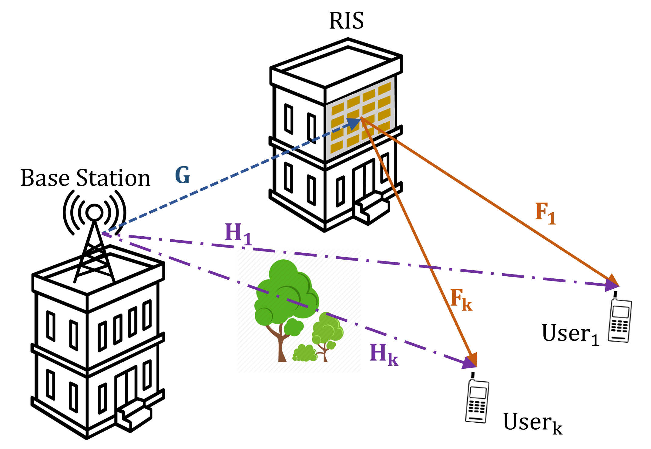
We consider a cellular network with BS, RIS, and users as shown in Fig. 1. We assume , , and as the number of antenna elements at the BS, RIS, and user, respectively, and formulate the equivalent channel between the BSand user as follows.
| (4) |
where, represents Hermitian operation, and , , and denote the channel coefficients between the BSto RIS, RISto the user , and the direct link between BSand user , respectively. Further, denotes the phase shift matrix at the RISformulated as follows [6, 3]

Note that ideal phase shifters are difficult to realize in practice. Thus, we formulate the discrete phase shifters as follows [15]
| (5) |
where denotes the number of discrete-levels at RIS. We consider the RIS-assisted downlink transmission for the user as follows.
where is the transmitted symbol corresponding to the user with unit power i.e., and is the maximum power the BScan transmit. Thus, we formulate the received signal at the user as follows.
| (6) |
where represents the additive white Gaussian noise at the user with zero mean and co-variance .
II-B 3-dimensional Channel Model
Typically, the physical size of the RISstructure is comparatively much smaller than the actual distance of the RISfrom the BSand user. Hence, we assume the far-field region while formulating the channel model [9]. Further, considering the various existing evaluations in the literature [11, 12, 13], we adapt the Generation Partnership Project (3GPP)based 3-dimension channel between the BS, RIS, and user [16, 11]. We define the clusters, sub-clusters, rays, angle of arrivals, angle of departures, path loss, shadow-fading, and small-scale fading as per the channel modeling formulated in [16]. The formulation of channel coefficients between the BS, RIS, and user (excluding the large scale fading parameters such as path loss and shadow fading) is summarized in (1)-(3), where subscripts , , and represent base stations, RIS, and user, respectively. and represent the angle of arrivals in azimuth and elevation, and angle of departures in azimuth and elevation, respectively. Based on the cellular environment (such as urban, rural, etc.), these angles are assigned considering various sub-rays corresponding to various clusters between the transmitter and receiver as per [14, 16]. , , and represent the antenna gains at the user, RIS, and BS, respectively. We consider the sectoral antenna pattern as per [16, 14] at the BSand omni directional antenna at the user. We model the transmissions from RISas just reflections (passive) i.e., with zero additional antenna gain (). captures the cross polarisation powers, represents the location vector, and represents the spherical unit vector for corresponding antenna elements, respectively. For the planar array shown in Fig. 1, the spherical unit vector is formulated as shown below [16].
| (7) |
represents the speed of the receiver and the corresponding exponential in (1) and (3) captures the Doppler effect. Note that no Doppler term is considered in (2), as we consider RISis stationary. Further, we also consider the path loss and shadow fading for each cellular environment as per [14].

III Proposed RISOrganization and Beamforming
III-A RISorganization
For the RIS-assisted cellular networks, we propose the RISorganization as shown in Fig. 2. The boresights of the sectors are considered to be in the directions of and the RISis placed at the edge of each sector with the boresight of RISelements facing the boresight of the BS. This organization of the BSorientations and positioning of the RIShelps in ensuring RISaccess to all the users in the sector. When compared to the scenario with boresight of the sectors in the direction of and RISplaced at cell-edge with its elements facing the boresight of the BS, the proposed organization has two key benefits as follows. With the proposed organization, the BSto RISdistance is instead of , where, indicates the inter-site distance. Note that the achievable gains with RIS-assisted systems are heavily dependent on the path loss observed in the BS-RIS-user link. Thus, with the proposed organization, the path loss observed will be minimal, and hence, enhanced signal reception can be achieved by the user. Further, with the proposed organization, the interference caused by the beamforming of the RISto the other sectors is also comparatively minimum, as the nearest neighbor sectors are not in the boresight direction of the RIS.
Lemma 1.
The optimal location for the RISto achieve a wider coverage is at the opposite end of the sector, with the boresight of the RISfacing the boresight of the BSantenna.

Proof.
We consider the circular approximation for a cell site and assume the 3-sector division as shown in Fig. 3 [17], where and are the sector divisions. We prove that is the optimal location of the RISfor the sector , and the same can be extended to the other sectors. Note that the reflections from the RISare observed on only one side of the RIS, and hence, to ensure RISaccess to the entire sector, RIShas to be placed only on the circumference of the sector . Further, the reflection amplitude of the RISis typically approximated as , where is the angle of incidence on RIS [5]. Thus, when RISis placed along the lines and but facing the sector, the signal from the base station is received at an angle of incidence of resulting in minimal gains. Also, note that typical BScellular antenna patterns have the least gains in the direction of sector-edges [14]. Thus, the optimal location of the RIScan only be on the arc .
As shown in Fig. 3, consider 3 points on the arc which are at and from the BSdenoted as and , respectively. Note that all three points are at the same distance from BS(or in Fig. 3). Thus, the distance-dependent path loss observed by the RISat these locations would be similar. Further, when we place RISat , the maximum distance of any user in the sector from does not exceed the radius of the sector . For example, is the farthest location from . Since, and , . However, this is not the case when the RISis placed at either or . The RISwill be closer to some users in the sector, but the farthest locations from and are and . This increase in the distance from RISto the users will result in decreased signal reception, and thus provides less coverage to these users when compared with the case of RISat . Hence, the optimal location of RISfor wider coverage is . This ends the proof of Lemma 1. ∎
III-B Beamforming design
To perform optimal beamforming at RISfor each user, the BShas to know the complete channel state information between RISand each user. However, this is not always achievable in practice. Hence, we propose a practically feasible beamforming design as follows. We configure number of predefined digital beams at the RISsuch that they cover the entire sector, as shown in Fig. 2. The number of beams can be decided by the network operator based on the number of antenna elements at the RIS. Given beams, the BScan tune the phase shifters at RISand activate one of the configured beams over various time slots. At the receiver, the user calculates the effective received signal strength from the configured beam and also the direct link from the BS. The user then reports back the best beam index to the BSin the uplink. For example, the best beam for users 1 and 2 in Fig. 2 are beam-and beam-3, respectively. This way, the BScan configure the desired beams at the RISwhile scheduling the data for each user. Note that a similar approach can also be adapted for the initial user attach. While transmitting the downlink synchronization signals, the BScan tune the phase shifters at RISand transmit different beams over various time slots such that the user can lock to the beam from which it receives maximum signal strength.


Remark 1.
The maximum achievable data rate for user in the presence of ideal phase shifters at RISis given by
| (8) |
Proof.
Lemma 2.
As , the maximum achievable data rate at user with discrete phase shifters at RISis given by
| (10) |
where represents the number of discrete-levels of the phase shifters at RISand represents the diagonal elements of .
Proof.
Using the optimal beamforming derived in (9) at RISwith discrete phase shifters, we get
| (11) |
where, denotes the element-wise (Hadamard) product and captures the quantization error. From (5), we obtain . Further, using (11), we get
where is a array and (a) is obtained by using Hadamard-product properties. By denoting as the diagonal elements of , we get
(b) is obtained by considering the law of large numbers [4], (c) is obtained assuming the independent nature of the random variables, (d) is obtained after integration of the odd symmetrical function over , and (e) is based on the assumption of the uniform distribution of over . Note that based on (9), also has the phase in the direction of , and thus, we get
| (12) |
This completes the proof of Lemma 2. ∎
Lemma 3.
As , the achievable data rates with the random phase shifters at RISare similar to that of the case with no RIS.
III-C Baseline algorithms considered for the evaluation
III-C1 Cellular system without any RIS
We consider cellular system without any RISas the baseline system for the comparison to understand the achievable gains with the introduction of RIS. Further, to ensure the correctness of the system-level modelling along with channel formulation, we have considered the antenna configuration and simulation parameters of the 3GPPPhase-2 Calibration [14] as the baseline and aligned the results with [14].
III-C2 Random phase shifters at the RIS [10, 1]
We evaluate the performance of the RIS-assisted cellular systems while applying random phase shifters (i.e., values of are assigned from complex random distribution with ) at the RISin each time slot [10].
IV Simulation Results and Discussion
| Parameter | Values |
|---|---|
| Cellular environment | Urban macro (UMa) [16] |
| Carrier frequency | 2 GHz |
| Path loss model | UMa [16] |
| System Bandwidth | 10 MHz |
| User drop | 10 per sector |
| BStransmit power | 43 dBm |
| Wraparound | Geographical distance based |
| RISdrop | 1 per sector |
| User attachment | Based on received signal power |
| Small scale model | 3GPPFD-MIMO [16] |
| BSantenna elements, | elements |
| BSantenna pattern | 3GPPsectoral pattern |
| User antenna elements, | 1 element |
| User antenna pattern | omni directional |
| RISantenna elements, | elements |
| RISantenna pattern | passive (only reflections modelled) |
| Thermal Noise | -174 dBm/Hz |
| Inter-cell interference | explicitly modelled from both RISs and BSs |
| Other general parameters | as per [14] |
The simulation parameters considered for the system-level evaluation of the proposed algorithms are presented in Table I. We have performed Monte-Carlo simulations in MATLAB and presented the achievable coupling loss, signal-to-interference-plus-noise ratio (SINR), and spectral efficiency with all the considered algorithms in Fig. 5. The coupling loss is calculated as the difference between the transmitted power and received power at each user. In Fig. 5, for the case without RIS, the coupling loss is aligned with the 3GPPPhase 2 Calibration curves presented in [14, 16], thus, ensuring the correctness of our implementation. As compared to the scenario with no RIS, the proposed design with ideal phase shifters achieves a 4 dB gain in the received signal power. The gains achievable with random phase shifters while using single RISare very minimal. Further, the proposed design with 4-bit discrete phase shifters also has significant improvement as compared to the scenario without any RIS. With the 12-bit discrete phase shifters, the coupling loss with the proposed design is similar to the coupling loss with ideal phase shifters.


We have calculated the SINRby explicitly capturing the interference from the neighboring BSand RISas follows.
| (14) |
where represents the interference captured from the neighbouring BSand RIStransmissions. In Fig. 5, the SINRfor the scenario without RISis aligned with 3GPPPhase 2 Calibration curves presented in [14], and thus, calibrating the SINRcalculation. As compared to the scenario with no RIS, the proposed design with ideal phase shifters achieves close to 2 dB improvement in the SINR. Note that despite the maximum of 4 dB gain in the coupling loss, we achieve only 2 dB improvements in the SINRbecause of the increase in the inter-cell interference caused by the addition of RISin the neighboring sectors. This reduction in SINRalso highlights the need for carrying out multi-cell analysis to quantify the practical gains with the inclusion of RIS. Further, for the same reason, all the cell-edge users do not observe similar interference, and hence, the pattern of achievable gains in coupling loss and SINRdiffer. Note that the performance of the random phase shifters is close to the scenario without any RISand the performance of the proposed RISwith 4-bit discrete phase shifters is also significantly better than the baseline algorithms. With the 12-bit discrete phase shifters, the SINRs of the proposed design are similar to the SINRs of the proposed design with ideal phase shifters. Further, the gains in spectral efficiency follow a similar pattern as that of the SINRs. As shown in Fig. 5, the proposed design achieves 30% improvement in spectral efficiency as compared to the baseline algorithms.
In Fig. 3, we present the comparison of achievable data rates for varying and . We show that the simulated results completely align with the theoretical analysis derived in Lemma 2 and 3. Note that with an increase in , the system performance with the random phase shifts does not change and is same as that of the case with no RIS. Further, with the increase in , the performance of the proposed design with discrete phase shifters converges to that of ideal phase shifters.
V Conclusion
In this letter, we have presented in detail the system-level modeling of the RIS-assisted cellular systems. Our numerical evaluations outline that only with the system-level evaluations the actual gains achievable with RIScan be understood. We have proposed a novel cellular layout and RISorganization which ensures uniform accessibility of the RISto all the active users in the desired sector and creates minimal interference to users in the neighboring cells. We have then proposed a beamforming design for the RIS-assisted cellular systems and analyzed the achievable gains with the proposed design by considering ideal and discrete phase shifters. Through extensive system-level analysis, we have shown that the proposed design achieves significant improvements in network performance when compared to the baseline algorithms. In the future, we plan to evaluate the proposed design on the hardware testbed.
References
- [1] Yashvanth L. and C. R. Murty, “Performance Analysis of Intelligent Reflecting Surface Assisted Opportunistic Communications,” arXiv, pp. 1–13, 2022. [Online]. Available: https://arxiv.org/pdf/2203.06313.pdf
- [2] P. Reddy M and A. Kumar, “User pairing and power allocation for irs-assisted noma systems with imperfect phase compensation,” IEEE Wireless Commun. Lett., vol. 11, no. 12, pp. 2492–2496, 2022.
- [3] F. Fang et al., “Energy-Efficient Design of IRS–NOMA Networks,” IEEE Trans. Veh. Technol., vol. 69, no. 11, pp. 14 088–14 092, 2020.
- [4] S. Zhou et al., “Spectral and Energy Efficiency of IRS-Assisted MISO Communication With Hardware Impairments,” IEEE Wireless Commun. Lett., vol. 9, no. 9, pp. 1366–1369, 2020.
- [5] Z. Shuhao et al., “Reconfigurable Intelligent Surface (RIS) Assisted Wireless Coverage Extension: RIS Orientation and Location Optimization,” IEEE Commun. Lett., vol. 25, no. 1, pp. 269–273, 2021.
- [6] Y. Xiu et al., “Reconfigurable Intelligent Surfaces Aided mmWave NOMA: Joint Power Allocation, Phase Shifts, and Hybrid Beamforming Optimization,” IEEE Trans. Wireless Commun., vol. 20, no. 12, pp. 8393–8409, 2021.
- [7] M. Zeng et al., “Sum Rate Maximization for IRS-Assisted Uplink NOMA,” IEEE Commun. Lett., vol. 25, no. 1, pp. 234–238, 2021.
- [8] J. Zhu et al., “Power Efficient IRS-Assisted NOMA,” IEEE Trans. Commun., vol. 69, no. 2, pp. 900–913, 2021.
- [9] V. Croisfelt et al., “A Random Access Protocol for RIS-Aided Wireless Communications,” arXiv:2203.03377, 2022.
- [10] Q. Gu et al., “System-level Simulation of Reconfigurable Intelligent Surface assisted Wireless Communications System,” arXiv:2206.14777, 2022.
- [11] E. Basar and I. Yildirim, “SimRIS channel simulator for reconfigurable intelligent surface-empowered mmWave communication systems,” in Proc. IEEE LATINCOM 2020, Nov. 2020, pp. 1–6.
- [12] E. Basar, I. Yildirim, and F. Kilinc, “Indoor and outdoor physical channel modeling and efficient positioning for reconfigurable intelligent surfaces in mmWave bands,” IEEE Trans. Commun., vol. 69, no. 12, pp. 8600–8611, Sep. 2021.
- [13] E. Basar and I. Yildirim, “Reconfigurable intelligent surfaces for future wireless networks: A channel modeling perspective,” IEEE Wireless Commun., vol. 28, no. 3, pp. 108–114, 2021.
- [14] 3GPP, “Study on 3D channel model for LTE,” 3GPP, Technical Report 36.873, v 12.7.0, Jan. 2018.
- [15] Z. Zhang and L. Dai, “A Joint Precoding Framework for Wideband Reconfigurable Intelligent Surface-Aided Cell-Free Network,” IEEE Trans. Signal Process., vol. 69, pp. 4085–4101, 2021.
- [16] 3GPP, “Study on channel model for frequencies from 0.5 to 100 GHz,” 3GPP, Technical Report 38.901, v 16.1.0, Jan. 2020.
- [17] G. Andrea, Wireless Communications. Cambridge Univ. Press, 2005.