Multi-Antenna Configuration with Reduced Passive Self-Interference for Full-Duplex Intelligent Transportation System
Abstract
In this paper, we propose a closely spaced multi-antenna system with passive self-interference cancellation (p-SIC) of dB between the transmitter and receiver antenna for full-duplex application. The p-SIC is achieved by field confinement near individual antennae using shorted metallic vias and the application of U-shaped perturbation in the ground plane. The p-SIC technique is initially implemented in a 1-Tx and 1-Rx antenna system and explained using transmission line-based theory. Further, it is extended to 1-Tx and 2-Rx configurations. Here the proposed full-duplex antenna system is designed at GHz ( GHz, IEEE 802.11p / WAVE technology) intelligent transportation system (ITS) application band using a microstrip patch configuration. The individual antenna exhibits an impedance bandwidth of MHz ( GHz), dBi gain at GHz operating frequency and X-pol level less than dB in the broad side direction. The proposed FD configuration exhibits of less than dB over the complete operating band and dB is achieved at the operating frequency between the Tx and Rx. Similarly, of less the dB is achieved between 2-Rx antennas for a three-element FD configuration. The design procedure of the proposed FD configuration is explained and verified using fabrication and measurement. An experimental demonstration of the self-interference channel and its suppression using the proposed p-SIC technique is also provided. Further, to study the diversity performance of the proposed multi-antenna configuration, the MIMO performance metrics such as ECC and CCL are evaluated using simulation and measurement.
Index Terms:
Full-Duplex, Microstrip Antenna, Self-Interference Cancellation, Intelligent Transportation System (ITS), V2X, MIMO, Mutual Coupling Reduction.I Introduction
Intelligent transportation system (ITS) is the future of vehicular wireless communication as the advanced driving experience and active safety are now priorities of every autonomous industry for upcoming vehicles. To reduce the impact on environment and to improve the traffic safety intelligent transportation systems (ITS) for vehicular communication such as vehicle-to-vehicle (V2V), vehicle-to-infrastructure (V2I) or in-short vehicle-to-everything (V2X) communication is the study of great interest for industry as well as academia [1]. A simplified architecture of ITS showing V2X connectivity is shown Fig. 1. In addition, ITS caters various smart applications such as safety warnings, emergency alert, vehicle platooning, vehicle internet, etc [2].

A report on legacy ITS and advanced ITS is provided in [3]. Accordingly, ITS is termed as cooperative-ITS (C-ITS) in Europe and some Asia-Pacific regions which work at the 5.855-5.925 GHz band. Similarly, in the USA and some other countries in North America dedicated short-range communication (DSRC) serves under ITS at the operating band of 5.850-5.925 GHz. Apart from C-ITS and DSRC, some other vehicular communication technologies such as V2X-WAVE (wireless access in the vehicular environment) and V2X- ITS connect come under ITS based on 5.9 GHz IEEE 802.11p standard [3].
The ITS application scenario, in contrast to conventional mobile communication, requires an antenna system enabling ultra-high reliability and low latency communication [4]. There are certain single antenna configurations for ITS application available in literature [5] - [7]. In [5], a low profile integrated microstrip antenna for dual-band application is proposed. A stacked slot antenna structure with additional slots on the top metallic part, floating metal layer, and reflector metal with additional dielectric layers is proposed in [6], which is quite bulky and may face integration issues in a vehicle. Similarly, a single left-hand circularly polarised (LHCP) antenna having mm2 size is proposed in [7]. However, future autonomous vehicles are expected to have a multi-antenna configuration, with 5G connectivity, installed at different parts of the vehicle to provide field-of-view [8], where a single antenna configuration is no longer a suitable solution for ITS application to cater the demand of ultra-high reliability and low latency.
Multi-antenna configuration based on full-duplex (FD) technology would be the best possible solution for ITS application considering the future requirements. Full-duplex topology concurrently uses time/frequency slots both for transmission and reception. This can be integrated with the 5G system over the conventional half-duplex (HD) system, which operates either frequency-division duplex (FDD) or time-division duplex (TDD), to improve the system efficiency [9]. A schematic of the HD and FD communication system is provided in Fig. 2 for better visualization. As far as ITS application is concerned, the simultaneous transmission and reception capability of FD system theoretically double the spectral efficiency of HD system [10], which eventually reduces latency [11]. In addition, the FD technology improves throughput [11] and provides high-speed ultra-reliable V2X link in vehicular communication [12]. Moreover, FD technology is one of the candidate technologies for future 6G services which facilitates enhanced capabilities than 5G counterpart (see Table 1)) [13] and can efficiently serve the ITS purpose. However, the key challenge in an FD system is the issue of self-interference due to the infliction of high-power local transmit a signal upon its own receiver, which leads to device saturation and failure in receiving actual signal of interest [14], [15]. To combat SI and make the FD system applicable in practice the high isolation of more than dB [16] (however it may vary based on the type of wireless system [17]) between the transmitter and receiver unit is highly desirable. In general, such high isolation is achieved jointly by passive(p) and active(a) SI-cancellation (SIC) techniques, where p-SIC deals with the antenna/propagation domain SIC and a-SIC deals with rf/analog and digital domain SIC [9], [18]. However, analog-SIC is not sufficient to provide enough isolation to restrict the saturation of active components such as LNA (low noise amplifier) and ADC (analog-to-digital converter) [19]. On the contrary, the antenna is the very first component in the rf front end which experiences all external stimuli and activates the rest of the rf component in the chain. Therefore, to reduce the system cost and burden on a-SIC stage, p-SIC technique (antenna isolation) is very much essential in an FD communication system.

There are various techniques have been reported to improve the inter-element isolation between the antenna elements, but either only in transmitting or receiving mode i.e in the HD scenario. For example, [20] provides an isolation improvement of dB using a parallel coupled line resonator between two microstrip antennas, isolation improvement of dB is achieved in [21] between two microstrip antennas using polarisation conversion isolator. Similarly, several other techniques such as defected ground structure [22], split-ring resonator [23], frequency selective surface [24] etc. result in improved isolation around dB are reported. It shows that due to either only transmission or reception capability of HD system there is no issue of SI here, where it can operate smoothly having limited antenna isolation. However, this is not the scenario in the FD communication system. There are various categories of SIC in FD antenna configuration available in the literature. Polarization multiplexing with hybrid-coupler-based SIC techniques is exploited in [25] - [28] and [29] to achieve very high inter-port isolation in expense of large size and stacked structure respectively. Similarly, a dual-polarized multi-layered antenna configuration with an additional feeding network and another dual polarized horn antenna configuration with high inter-port isolation for FD communication are proposed in [30] and [31] respective. However, due to their multi-layered and bulky structure, these are not suitable for integration in compact modules. A dual-polarized rectangular cavity-backed antenna with high inter-port isolation is described in [32]. The antenna has a 3D volumetric structure with very complex design and integration challenges. Co-linearly polarized compact size microstrip antenna with fence-strip resonator (FSR) for good isolation between transmitter and receiver port, a stacked structure FD antenna with the combination of a microstrip and surface integrated waveguide cavity backed slot antenna with cavity-patch coupling (CPC) path is added for cancelling the slot-patch coupling (SPC) by using four probe and surface integrated wave guide based FD antenna with SIC using metallic vias are proposed in [33], [34] and [35] respectively. However, the techniques proposed in [33] - [35] provides SIC between dB, which is quite limited for FD communication. In our earlier work, a very closely spaced planer FD antenna configuration having dB inter-port isolation, at the operating frequency, between the antenna elements is proposed in [15].
| Performance parameter | 5G | 6G |
|---|---|---|
| Energy Efficiency | ||
| Spectral Efficiency | ||
| Air Latency (ms) | ||
| Connection Density (devices/km^2) | ||
| Reliability | ||
| Peak Data Rate (Gbps) | ||
| User Experience Data Rate (Gbps) |
Therefore, considering the application scenario and requirement for FD communication system in ITS, in this paper, we propose a very closely spaced planer easy to integrate FD antenna systems with a very high p-SIC. This work builds upon work earlier work [36] by: (i) a detailed explanation for 2-element FD-antenna (1-Tx and 1-Rx) design steps and working mechanism of proposed p-SIC technique, (ii) extension of 2-element FD-antenna to 3-element antenna system having 1-Tx and 2-Rx (or 2-Tx and 1-Rx) configuration followed by fabrication, measurement and study of multi-antenna (MIMO) performance, and (iii) experimental demonstration of the real-time self-interference channel and its suppression using proposed p-SIC technique. To the best of the authors’ knowledge, a compact FD antenna configuration having more than dB of p-SIC and antenna performance parameters such as a gain of dB, a cross-polar level less than dB with good MIMO diversity for ITS application is not available in the open literature.
II Design and p-SIC Mechanism of two element (1-Tx and 1-Rx) Full Duplex Antenna System
The 3D perspective view of the proposed two port (1-Tx and 1-Rx) FD antenna is shown in Fig. 3. The antenna is designed on the RTD 5880 dielectric substrate having dielectric constant , dielectric loss tangent and mm thickness (). The overall substrate dimension is mm mm). In this section, the design stages of the proposed FD structure with the p-SIC (antenna isolation) mechanism are discussed. For every design stage the corresponding E- and H- field distribution along the isolation parameter (, where ) are utilised to illustrate the operating mechanism.

II-A Design Stage-1
Initially, two element inset-fed microstrip patch antennas are placed in a closed proximity () with orientation representing Tx and Rx antenna for FD communication as shown in Fig. 4. The inset-fed structure is powered through a co-axial probe. The dimensions (see Fig. 4) of physical notch width (), width of microstrip feed line () and the inset depth () are considered to maintain the individual antenna input impedance at the operating frequency which can be approximately computed using the following equations [37], [38]
| (1) |
| (2) |
where and are the input impedance of the patch at and zero inset depth respectively. is the radiating edge conductance of the patch and denotes the substrate thickness. and represent the free space wave-number and wavelength respectively.
The individual antenna element operates in fundamental mode at GHz operating frequency having dB impedance bandwidth (IBW)(See Fig. 5). Fig. 5 (a) and (b) depict the E- and H-field distribution showing the strong inter-element coupling between the antenna elements, which can also be observed from the S-parameter curve in Fig. 5(c) having very high value of dB. This strong coupling is due to the close inter-element spacing and identical polarization of the Tx and Rx antennas.


II-B Design Stage-II
Fig. 6 shows the schematic of antenna design at stage-II. In this design stage, initially two shorting vias are placed at two corners of Tx (@, see Fig. 4) and RX (@, see Fig. 4) antenna elements. Further, a series of shorting vias are placed along at distance away from the non-radiating edges of the antennas along the direction, see Fig. 6. Here, the shorting via diameter () and distance between two consecutive vias () are mm and mm respectively. The objective of this design stage is reduce the high field coupling zone in the antenna elements and to limit the power flow between the Tx and Rx antenna by restricting the surface wave. It is evident from Fig. 5 (a) that the E-field coupling intensity has reduced compared to stage-I, which is also reflected in S-parameter response (see Fig. 7(c). The parameter is reduced to dB in this stage. The stage-II design exhibits no adverse effect to antenna polarization and operating frequency though it reduces the antenna IBW to .
II-C Design Stage-III
In this stage, to reduced the H-field coupling present in stage-II (see Fig. 7(b)) and to further reduce the E-field coupling, a series of shorting vias are placed at E-field minima positions (see Fig. 7(a)) of both Tx and Rx antenna along -direction as shown in Fig. 8. The shorting pin dimension and the relation gap between the pins are kept identical as in stage-II. The loading of shorting vias along width of the patch at the zero potential location reduces the antenna size and made antenna operate at mode. It is clearly visible in the Fig. 9 (a) and (b) that the changes made in this design stage reduces the field coupling compared to stage-II (see Fig. 7). Similarly, the response reduces to dB without affecting antenna impedance matching and bandwidth. The isolation achieved in this stage is suitable for HD applications, however this is not desirable for a FD systems.


II-D Design Stage-IV
In this stage, two U-shaped perturbations are incorporated in the ground plane near the feed locations of both Tx and Rx to achieve the desired p-SIC (antenna isolation) between the Tx and Rx antennas. The schematic of the final FD antenna configuration is depicted in Fig. 10. The proposed antenna arrangement with the ground plane perturbation provides band-stop characteristics, which can easily be explained using the transmission line analogy.


- •
p-SIC (Antenna Isolation) Mechanism using Transmission Analogy: A microstrip transmission line is designed at GHz operating frequency, as shown in Fig. 11 (inset), on a RTD 5880 substrate to best describe the proposed antenna configuration. , , p1 and p2 are the length, width and the two ports of the transmission line respectively. dB response of Fig. 11 for the transmission line without slots shows a passband response centered at GHz operating frequency. Further, two U-shaped perturbations are incorporated in the ground plane (i.e. defected ground structure (DGS)) of the transmission line near p1 and p2, as shown in Fig. 11 (inset). Similarly, the dB response of the two DGSs loaded transmission line showing the stop-band response () at 5.9 GHz operating frequency is shown in Fig. 11. The design guidelines and equivalent circuit model of the DGS can be found from [39], where the length () and width () of the DGS defines the resonant frequency which can be represented using an equivalent circuit.
The analysis can be re-direct to the stage-IV response as shown in Fig. 12. Fig. 12 (a) and (b) show the E- and H-field distributions of the final FD antenna configuration shown in Fig. 10, which depict approximately no field coupling between the Tx and Rx antenna element. This can also be observed in the S-parameter curve in Fig. 12 (c), where the isolation () is dB at the GHz operating frequency and more the dB over the operating band ( GHz), which is very high compared to earlier stage-I and suitable for FD application. Dimensions of DGS, and are obtained using parametric study, as described in [36] to get the best possible p-SIC between the Tx and Rx antennas.
- •
Effect of Ground Plane on Proposed FD Antenna Performance: The parametric studies on the antenna ground plane dimensions ( and ) are conducted as shown in Fig. 13 (a) and (b). It can be observed in Fig. 13 (a) and (b) that isolation between the antenna elements varies with the variation of the antenna ground plane. The variation in the ground plane varies the electrical path length of the current distribution between the slots and eventually changes the effective inductive reactance introduced by the slots at the operating frequency [40], thereby changing the isolation between antenna elements. However, the antenna parameter is unaffected (see Fig. 13(a) and (b)) as the ground plane variation does not affect the current distribution in the radiating patch. The stated design parameters for the proposed antenna are chosen for the ground plane size of mm mm to adequately confined the microstrip antenna fringing field and to get the best possible antenna performance.


III Design of Multi-Element (Tx and Rx) Full Duplex Antenna System
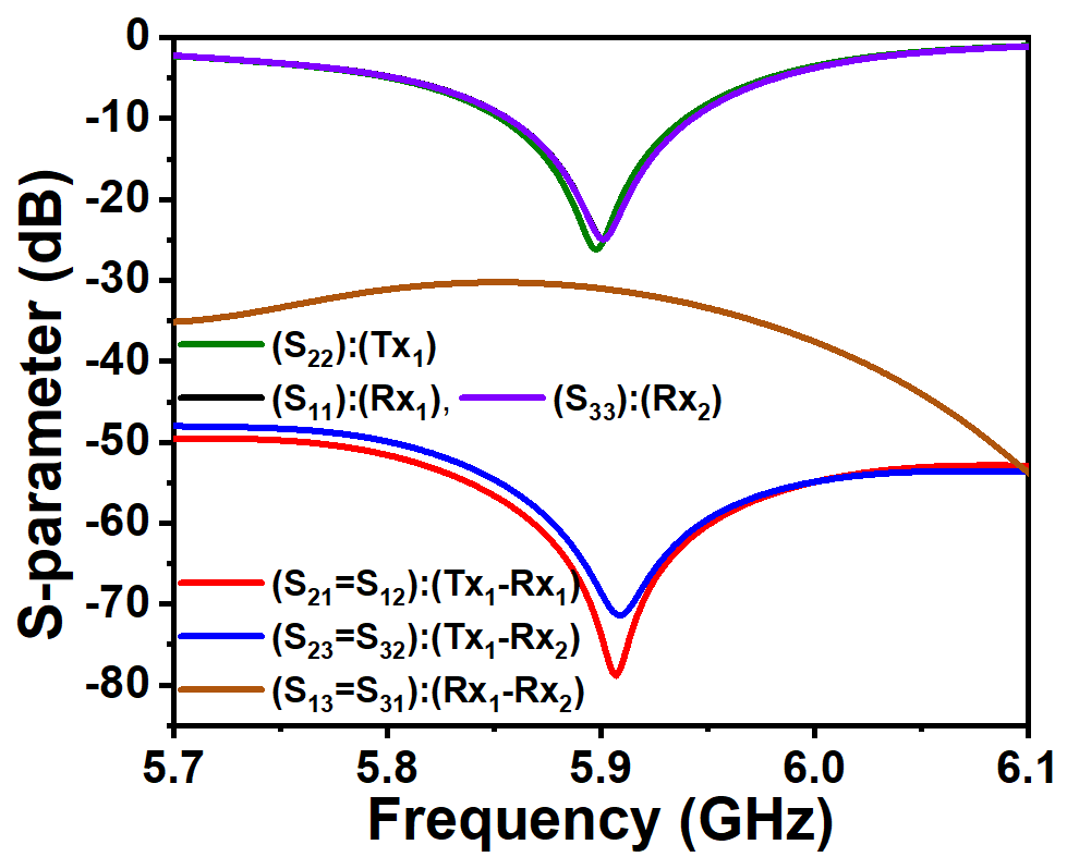
The Tx and Rx FD antenna system is extended to Tx and Rx FD system to verify the design scalability of the proposed p-SIC technique. Moreover, the multi-antenna receiver system provides the additional degree of freedom to improve the system diversity, i.e. the capability of multiple-input multiple-output (MIMO) configuration, in a multi-path crowded application environment as in ITS. The schematic of the proposed element (Tx and Rx) FD antenna system is shown in Fig. 14. The S-parameter response of this FD configuration is provided in Fig. 15, illustrates more than dB p-SIC between - and - at the 5.9 GHz operating frequency, which satisfies the FD requirements. Moreover, the isolation between two Rx element is more than 30 dB over the operating band full fills the MIMO requirement. S-parameter response in Fig. 15 signifies that the proposed p-SIC technique is also applicable to the element FD system with a minor design modification on , and . The modified design parameters are provided in Fig. 14.

IV Prototype Fabrication and Measurement Results
The fabricated prototype of the proposed two and three element FD antenna system are shown in Fig. 16 and 17 respectively. The S-parameters of these two and three element prototypes are measured using Agilent N5230A PNA and compared with the simulation results as shown in Fig. 18 and 19 respectively with their measurement set-up. Similarly , the 2D radiation pattern of Tx antenna element showing the simulated and measured curves of two and element configuration are provided in Fig. 20 and 21 respectively. The X-pol level of the two and three element configuration is below dB. The measured results are in good agreement with the simulated ones, which validates the proposed p-SIC technique. A complete performance parameters of the proposed FD antenna configuration provided in table II.


| Parameter | value |
|---|---|
| No of antenna element | (-Tx and -Rx) |
| Operating Frequency | GHz |
| Impedance Bandwidth | MHz |
| Maximum Gain | dBi |
| Total efficiency | |
| Cross polar level | dB |
| Maximum \textit{p}-SIC | dB |
| Application | FD ITS |

IV-A Experimental Demonstration of Self-Interference Channel Between Tx and Rx and Its Suppression using Proposed p-SIC Technique
We carried out two-set of experiments using stage-I (See Fig. 4) and stage-IV (see Fig. 10) FD antenna to visualize the real-time self-interference between Tx and Rx. The schematic representation of experimental set-up is shown in Fig. 22, as described in [41]. Here, we use Adalm-Pluto software defined radio (SDR) through the MATLAB’s-Simulink as a source (transmitter) and Tektronix RSA306B real-time spectrum analyser as receiver connected to Tx and Rx of FD-antenna respectively as shown in Fig. 22. Fig. 23 (a) and (b) show the real-time experimental set-up using proposed stage-I and stage-IV FD-antenna along with the DPX (Digital Phosphor Technology)-spectrum indicating the self-interference between the Tx and Rx of FD antenna when operating simultaneously. It is clearly observed that the FD-antenna having least Tx-Rx coupling (see Fig. 23(a)) shows nearly no interference above system noise floor (here dB) compared to FD-antenna having high Tx-Rx coupling (see Fig. 23(a)), which exhibits very high (nearly dB above system noise floor) signal interference. This signifies the practical utility of the proposed p-SIC technique.


IV-B MIMO Performance Parameters
MIMO performance study of the proposed two and three element FD antenna configuration is carried out by evaluating envelop correlation coefficient (ECC) and channel capacity loss (CCL) in the operating band (see Fig. 24 (a) and (b)) as discussed in [15]. The value of ECC is much less than 0.5 in the uniform propagation environment, which indicates excellent diversity performance, which is further reflected in the low value of channel capacity loss ( bits/s/Hz) in the operating band.


V Conclusion
In this paper, the design of a two-element, as well as a three-element inset-fed antenna configuration for FD implementation, are presented along with a novel p-SIC technique between the antenna elements. The complete proposed FD antenna configuration, together with p-SIC technique, is planar in form, easy to implement, and avoids the conventional use of bulky hybrid coupler-based FD antenna technique to achieve high p-SIC. The mechanism of the proposed p-SIC technique along with antenna design steps is described using field distribution between the antenna elements and DGS loaded microstrip line analogy. The p-SIC technique provides the maximum isolation of dB and dB for two and element FD antenna configuration respectively. It is verified using a real-time experimental demonstration using SDR and SA that the proposed p-SIC effectively suppresses the unwanted signal interference in Rx from its own Tx. Further, MIMO performance parameters such as ECC and CCL are evaluated to study the diversity performance of the proposed FD antenna systems. The antenna configurations are best suitable for FD ITS application.
VI Acknowledgement
Authors would like to thank Prof. K. J. Vinoy, Chair, Dept. of ECE, IISc Bangalore for providing the measurement facilities (PNA and Anechoic chamber). Authors would also like to thank Mr. Debaprasad Barad (M. Tech, Res) and Mr. Yugesh Chandrakapure (M. Tech), ECE, IISc Bangalore for their help in fabrication and measurement respectively. This work is jointly supported by IoE-IISc postdoctoral fellowship and SID-IISc.
References
- [1] Y. Fang, "Connected Vehicles Make Transportation Faster, Safer, Smarter, and Greener!," in IEEE Transactions on Vehicular Technology, vol. 64, no. 12, pp. 5409-5410, Dec. 2015.
- [2] J. E. Siegel, D. C. Erb and S. E. Sarma, "A Survey of the Connected Vehicle Landscape—Architectures, Enabling Technologies, Applications, and Development Areas," in IEEE Transactions on Intelligent Transportation Systems, vol. 19, no. 8, pp. 2391-2406, Aug. 2018.
- [3] Intelligent transport systems (ITS) usage, report ITU-R M.2445-0, ITU-R, International Telecommunication union, 2018. [Online] Available: https://www.itu.int/dms_pub/itu-r/opb/rep/R-REP-M.2445-2018-PDF-E.pdf.
- [4] C. B. Lehocine, E. G. Ström and F. Brännström, "Hybrid Combining of Directional Antennas for Periodic Broadcast V2V Communication," in IEEE Transactions on Intelligent Transportation Systems, doi: 10.1109/TITS.2020.3033094.
- [5] G. Z. Rafi, M. Mohajer, A. Malarky, P. Mousavi and S. Safavi-Naeini, "Low-Profile Integrated Microstrip Antenna for GPS-DSRC Application," in IEEE Antennas and Wireless Propagation Letters, vol. 8, pp. 44-48, 2009.
- [6] T. Ijiguchi et al., "Circularly Polarized One-Sided Directional Slot Antenna With Reflector Metal for 5.8-GHz DSRC Operations," in IEEE Antennas and Wireless Propagation Letters, vol. 13, pp. 778-781, 2014.
- [7] O. Leonardi, M. G. Pavone, G. Sorbello, A. F. Morabito, and T. Isernia, “Compact single-layer circularly polarized antenna for shortrange communication systems,” Microw. Opt. Technol. Lett., vol. 56, no. 8, pp. 1843–1846, 2014.
- [8] S. Roger et al., "5G V2V Communication With Antenna Selection Based on Context Awareness: Signaling and Performance Study," in IEEE Transactions on Intelligent Transportation Systems, doi: 10.1109/TITS.2020.3019530.
- [9] K. E. Kolodziej, B. T. Perry and J. S. Herd, "In-Band Full-Duplex Technology: Techniques and Systems Survey," in IEEE Transactions on Microwave Theory and Techniques, vol. 67, no. 7, pp. 3025-3041, July 2019.
- [10] H. V. Nguyen et al., "On the Spectral and Energy Efficiencies of Full-Duplex Cell-Free Massive MIMO," IEEE J. Sel. Areas Commun., vol. 38, no. 8, pp. 1698-1718, Aug. 2020.
- [11] F. Abbas, X. Yuan, M. S. Bute and P. Fan, "Performance Analysis Using Full Duplex Discovery Mechanism in 5G-V2X Communication Networks," in IEEE Transactions on Intelligent Transportation Systems, doi: 10.1109/TITS.2021.3103974.
- [12] C. Campolo, A. Molinaro, A. O. Berthet and A. Vinel, "Full-duplex radios for vehicular communications," in IEEE Communications Magazine, vol. 55, no. 6, pp. 182-189, June 2017.
- [13] 6G The Next Hyper-Connected Experience for All, White paper Samsung Research. [Online] Available: https://research.samsung.com/next-generation-communications.
- [14] J.I. Choi, M. Jain, K. Srinivasan, et al.:"Achieving single channel, full duplex wireless communication". Mobicom’10, IL, USA, September 2010, pp. 1–12.
- [15] J. C. Dash and D. Sarkar, "Microstrip Patch Antenna System With Enhanced Inter-Port Isolation for Full-Duplex/MIMO Applications," in IEEE Access, vol. 9, pp. 156222-156228, 2021.
- [16] A. Sabharwal, P. Schniter, D. Guo, D. W. Bliss, S. Rangarajan and R. Wichman, "In-Band Full-Duplex Wireless: Challenges and Opportunities," in IEEE Journal on Selected Areas in Communications, vol. 32, no. 9, pp. 1637-1652, Sept. 2014.
- [17] H. Zhao et al., "A Broadband Multistage Self-Interference Canceller for Full-Duplex MIMO Radios," in IEEE Transactions on Microwave Theory and Techniques, vol. 69, no. 4, pp. 2253-2266, April 2021.
- [18] K. Gbafa, A. Diallol, P. L. Thuc, and R. Staraj, “Tx/Rx antenna system for full-duplex application,” in Proc. IEEE Int. Symp. Antennas Propag. USNC/URSI Nat. Radio Sci. Meeting, Boston, MA, USA, Jul. 2018, pp. 1571–1572.
- [19] A. Batgerel and S. Y. Eom, “High-isolation microstrip patch array antenna for single channel full duplex communications,” IET Microw., Antennas Propag., vol. 9, no. 11, pp. 1113–1119, Aug. 2015.
- [20] K. S. Vishvaksenan, K. Mithra, R. Kalaiarasan and K. S. Raj, "Mutual Coupling Reduction in Microstrip Patch Antenna Arrays Using Parallel Coupled-Line Resonators," in IEEE Antennas and Wireless Propagation Letters, vol. 16, pp. 2146-2149, 2017.
- [21] Y. Cheng, X. Ding, W. Shao and B. Wang, "Reduction of Mutual Coupling Between Patch Antennas Using a Polarization-Conversion Isolator," in IEEE Antennas and Wireless Propagation Letters, vol. 16, pp. 1257-1260, 2017
- [22] H. Xing, X. Wang, Z. Gao, X. An, H.-X. Zheng, M. Wang, and E. Li, "Efficient isolation of an MIMO antenna using defected ground structure," Electronics, vol. 9, no. 8, p. 1265, Aug. 2020.
- [23] D. Sarkar and K. V. Srivastava, “A compact two-port MIMO antenna with enhanced isolation using SRR-loaded slot-loop,” in Proc. IEEE Appl. Electromagn. Conf. (AEMC), Aurangabad, India, Dec. 2017, pp. 1–2.
- [24] T. Hassan, M. U. Khan, H. Attia, and M. S. Sharawi, “An FSS based correlation reduction technique for MIMO antennas,” IEEE Trans. Antennas Propag., vol. 66, no. 9, pp. 4900–4905, Sep. 2018.
- [25] H. Nawaz and I. Tekin, "Dual-Polarized, Differential Fed Microstrip Patch Antennas With Very High Interport Isolation for Full-Duplex Communication," in IEEE Transactions on Antennas and Propagation, vol. 65, no. 12, pp. 7355-7360, Dec. 2017.
- [26] H. Nawaz and I. Tekin, "Double-Differential-Fed, Dual-Polarized Patch Antenna With 90 dB Interport RF Isolation for a 2.4 GHz In-Band Full-Duplex Transceiver," in IEEE Antennas and Wireless Propagation Letters, vol. 17, no. 2, pp. 287-290, Feb. 2018.
- [27] L. Y. Erol, A. Uzun, M. Seyyedesfahlan and I. Tekin, "Broadband Full-Duplex Antenna for IEEE 802.11 Protocols," in IEEE Antennas and Wireless Propagation Letters, vol. 20, no. 10, pp. 1978-1982, Oct. 2021.
- [28] H. Nawaz and I. Tekin, “Compact dual-polarized microstrip patch antenna with high interport isolation for 2.5 GHz in-band full-duplex wireless applications,” IET Microw., Antennas Propag., vol. 11, no. 7, pp. 976–981, Jun. 2017.
- [29] M. V. Kuznetcov, S. K. Podilchak, A. J. McDermott and M. Sellathurai, "Dual-Polarized High-Isolation Antenna Design and Beam Steering Array Enabling Full-Duplex Communications for Operation Over a Wide Frequency Range," in IEEE Open Journal of Antennas and Propagation, vol. 2, pp. 521-532, 2021.
- [30] Y. -M. Zhang and J. -L. Li, "A Dual-Polarized Antenna Array With Enhanced Interport Isolation for Far-Field Wireless Data and Power Transfer," in IEEE Transactions on Vehicular Technology, vol. 67, no. 11, pp. 10258-10267, Nov. 2018.
- [31] F. Chen, R. Morawski and T. Le-Ngoc, "Self-Interference Channel Characterization for Wideband 2 × 2 MIMO Full-Duplex Transceivers Using Dual-Polarized Antennas," in IEEE Transactions on Antennas and Propagation, vol. 66, no. 4, pp. 1967-1976, April 2018.
- [32] M. Amjadi and K. Sarabandi, "Ultra-Wideband, Compact, and High-Gain Two-Port Antenna System for Full-Duplex Applications," in IEEE Transactions on Antennas and Propagation, vol. 69, no. 11, pp. 7173-7182, Nov. 2021.
- [33] Y. He and Y. Li, "Compact Co-Linearly Polarized Microstrip Antenna With Fence-Strip Resonator Loading for In-Band Full-Duplex Systems," in IEEE Transactions on Antennas and Propagation, vol. 69, no. 11, pp. 7125-7133, Nov. 2021.
- [34] W. Zhang, J. Hu, Y. Li and Z. Zhang, "Design of a Stacked Co-Polarized Full-Duplex Antenna With Broadside Radiation," in IEEE Transactions on Antennas and Propagation, vol. 69, no. 11, pp. 7111-7118, Nov. 2021.
- [35] A. Iqbal, I. B. Mabrouk, M. Al-Hasan, M. Nedil and T. A. Denidni, "Wideband Substrate Integrated Waveguide Antenna for Full-Duplex Systems," in IEEE Antennas and Wireless Propagation Letters, vol. 21, no. 1, pp. 212-216, Jan. 2022.
- [36] J. C. Dash and D. Sarkar, "A Co-Linearly Polarized Full-Duplex Antenna With Extremely High Tx-Rx Isolation," IEEE Antennas and Wireless Propagation Letters (Early Access), 2022. DoI: 10.1109/LAWP.2022.3194135.
- [37] L. I. Basilio, M. A. Khayat, J. T. Williams and S. A. Long, "The dependence of the input impedance on feed position of probe and microstrip line-fed patch antennas," in IEEE Transactions on Antennas and Propagation, vol. 49, no. 1, pp. 45-47, Jan 2001.
- [38] C. A. Balanis, Antenna Theory: Analysis and Design. Hoboken, NJ: Wiley, 2016.
- [39] D. Ahn, J. . -S. Park, C. . -S. Kim, J. Kim, Y. Qian and T. Itoh, "A design of the low-pass filter using the novel microstrip defected ground structure," IEEE Transactions on Microwave Theory and Techniques, vol. 49, no. 1, pp. 86-93, Jan. 2001.
- [40] C. S Kim, J. S Park, D. Ahn, and J. B. Lim, “A novel 1-D periodic defected ground structure for planar circuits,” IEEE Microwave and Guided Wave Letters, vol. 10, no. 4, pp. 131-133, April 2000.
- [41] H. Zhao et al., "A Broadband Multistage Self-Interference Canceller for Full-Duplex MIMO Radios," IEEE Transactions on Microwave Theory and Techniques, vol. 69, no. 4, pp. 2253-2266, April 2021.