LEFM is agnostic to geometrical nonlinearities arising at atomistic crack tips Note: Linear Elastic Fracture Mechanics Journal: Forces in Mechanics
Abstract
Various fields such as mechanical engineering, materials science, etc., have seen a widespread use of linear elastic fracture mechanics (LEFM) at the continuum scale. LEFM is also routinely applied to the atomic scale. However, its applicability at this scale remains less well studied, with most studies focusing on non-linear elastic effects. Using a harmonic "snapping spring” nearest-neighbor potential which provides the closest match to LEFM on a discrete lattice, we show that the discrete nature of an atomic lattice leads to deviations from the LEFM displacement field during energy minimization. We propose that these deviations can be ascribed to geometrical nonlinearities since the material does not have a nonlinear elastic response prior to bond breaking. We demonstrate that crack advance and the critical stress intensity factor in an incremental loading scenario is governed by the collectively loaded region, and can not be determined analytically from the properties (max. elongation, max. sustained force, etc.) of the stressed crack tip bond alone.
Keywords:
LEFM , Fracture toughness , Lattice trapping , Atomistic Simulation , Harmonic Potential1 Introduction
Linear elastic fracture mechanics (LEFM) has a long history in structural integrity and the design of fracture-resistant materials, and is well established in literature [1]. The roots of LEFM trace back to the works of Inglis [2] who introduced the concept of a stress concentration factor to describe the stresses due to an elliptical hole with respect to an applied macroscopic stress. Later, Griffith [3] assumed a linear elastic material to establish a thermodynamic criterion for perfectly brittle crack advance. According to this model, a crack would propagate when the the stored elastic energy released by crack propagation exceeds the energy required to create two new crack surfaces. The energy release rate , which can be defined as the rate of change in potential energy with crack area, can then be related to Griffith’s criterion as follows:
| (1) |
where is Griffith’s theoretical resistance of the material that needs to be overcome to create two crack new surfaces, with being their surface energy. Williams [4] and Irwin [5] then used a stress-based approach to establish the concept of a stress intensity factor (SIF). This factor is a single loading parameter that describes the scaling of the amplitude of the stress field around the crack. The stress intensity factor is related to the energy release rate as follows:
| (2) |
where is the orientation dependent elastic modulus. Applying the Griffith criterion to the stress-based approach using equations (1) and (2), we obtain the theoretical SIF required for crack advance:
| (3) |
In atomistic simulations of fracture [6, 7], a SIF-controlled loading approach is usually employed by displacing atoms according to the linear elastic anisotropic solution in plane strain in mode I [8]. The LEFM displacement field is given by:
| (4) |
| (5) |
where is the stress intensity factor under mode I loading and is the distance of the atom from the mathematical center of the crack tip. The angular distribution functions and are defined by the angle to the cleavage plane and the elastic constants for a given crystallographic orientation. Although a crack is initially inserted by displacing all atoms, it is only the boundary layers that are kept fixed during the simulations while the remaining atoms are allowed to relax to their minimum energy configuration (see, e.g.,[6]). Furthermore, an explicit failure criterion is not required in atomistic simulations. Rather, the fracture toughness is a result of these simulations. It can be considered to be reached when, as a result of an energy minimization under the applied displacement field, the separation distance of the crack tip atom pair exceeds some critical value [9, 10].
As the name suggests, a key assumption in LEFM is that the material exhibits linear elastic behavior. Deviations from linear elastic behavior could be due to material nonlinearities, geometrical nonlinearities and time-history dependence [11]. Material nonlinearities comprise of, for example, nonlinear elastic response or plasticity. Geometrical nonlinearities are due to large deformations where an explicit distinction is to be made between reference and deformed configurations [12]. Deviations due to time-history dependence are usually ascribed to viscoelasticity, creep and fatigue [11].
Previous works with material-specific models such as [13, 10] have shown that there is generally a good agreement between LEFM and atomistics as far as stresses are concerned. The atomic stresses match LEFM away from the crack tip and close to the boundaries where the LEFM displacement field is imposed throughout the simulations. Deviations arise only below about 1 nm distance from the crack tip and resolve to finite values. However, these deviations do not invalidate the loading procedure in the simulations since the accompanying changes in energy are localized close to the crack tip [6]. Such deviations are gerenerally ascribed to material nonlinearities, without explicitly taking into account possible other nonlinearities.
It should also be noted that the determination of atomic stresses at the crack tip is non-trivial. For example, the study by Möller et al. [10] observed that the Virial method [14] used to measure stresses led to deviations at the crack tip due to atomic volumes being ill-defined at surfaces.
The phenomenon of lattice trapping (which can be generalized to bond trapping for interfaces [15]) represents a deviation for atomic structures from Griffith’s energy based approach to LEFM (see [16]). The discrete nature of a lattice prevents the continuous increase of crack surfaces by a continuously propagating crack. Instead, cracks propagate by breaking individual atomic bonds. This leads to cracks remaining stable above and below the Griffith stress intensity factor during loading and unloading, respectively. While the phenomenon of bond trapping is well established in the literature (see, e.g, the references in [7]), the influence of geometrical nonlinearities on lattice trapping have not yet been studied in detail.
In this study, we provide an example to quantify deviations from the SIF-controlled LEFM displacement field arising from geometric nonlinearities and their contribution to the lattice trapping phenomenon. As a consequence, we show that fracture toughness cannot be analytically determined based on knowledge of maximal bond length of crack tip bonds alone. Towards this end, we use a harmonic potential with a local cutoff to circumvent nonlinear elastic response prior to cleavage, similar to studies such as [9, 17]. The use of such a potential between atoms is analogous to a "network of springs" model, which is widely used in the study of fracture mechanics [18].
2 Method
The pair force of the harmonic "snapping spring" potential was given by:
| (6) |
where is the potential energy at the equilibrium distance , is the cutoff distance, and is the inter-atomic separation distance. This potential leads to a face-centered-cubic (fcc) equilibrium structure. The parameters and potential properties are listed in table 1. The cutoff of the potential has to be small enough to be strictly local so that linearity is ensured and that cleavage of bonds at the crack tip can take place [17]. Consequently, the critical separation distance between atoms for cleavage coincides with the cutoff . The local nature of the potential also results in the simulations not displaying any surface related phenomena, which are not accounted for in LEFM, making this potential suitable for comparisons with LEFM. Two different parameterization of this harmonic potential have been investigated and resulted in comparable conclusions (the details and results of the second potential are in A and C).
| Parameters / Properties | Value |
|---|---|
| (eV) | 1.00 |
| () | 2.54 |
| () | 3.07 |
| (eV) | -6.00 |
| () | 3.60 |
| (J/m2) | 4.95 |
| (GPa) | 642.92 |
| (GPa) | 321.59 |
| (GPa) | 321.59 |
Cylindrical pacman-like configurations with radii of and depths of about were used, see Fig. 1. Without removing atoms or deleting bonds, LEFM near crack tip solutions according to equations (4) and (5) were used to create and load cracks. A boundary region of about thickness was kept fixed throughout the simulations, whereas the remaining domain was allowed to relax. The sizes of the configurations were large enough to converge to the infinite limit assumed by LEFM with respect to (see B). Hence, flexible boundary conditions as detailed in [19] were not required. Instead, the LEFM displacement field and boundaries were always centered on the geometrical center of the configurations, similar to works such as [10, 20, 21]. The crack systems (characterized by crack plane and crack front direction) studied were (100)[001] and (100)[011].
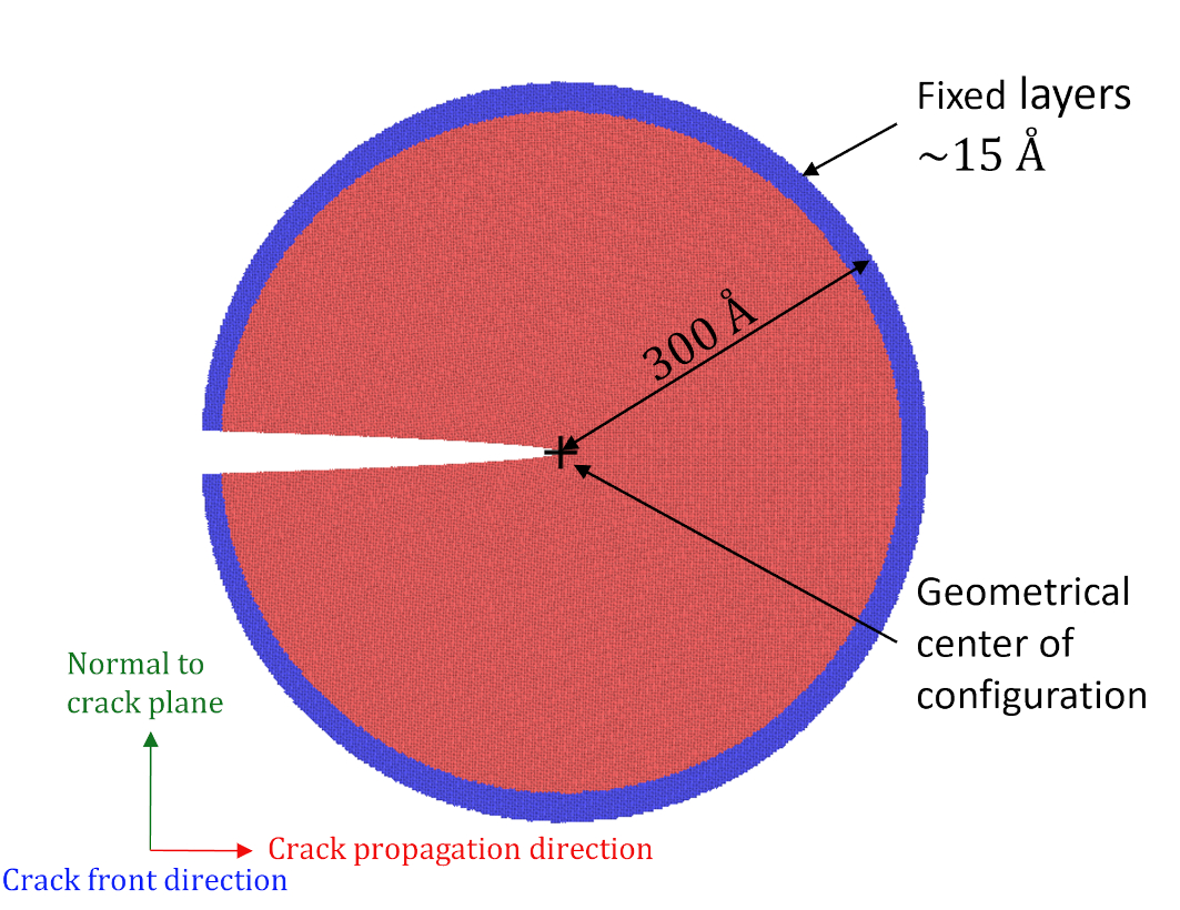
The initial prescriptions of the displacement field were done at a load where the cracks were stable at the center of the configurations (), see table 2 for the values of and . The configurations were then minimized using FIRE [22]. Two procedures were used in this study to impose further loads: incremental and total loading. In incremental loading, further loads in the form of prescribed displacements according to equations (4) and (5) were incrementally applied on all the atoms in the relaxed configuration of the previous load increment until the crack tip bonds underwent cleavage (). The fracture toughness determined that way are referred to by . In the case of total loading, displacements according to the total desired load were directly applied to the initial, uncracked cylinder. The sample were then relaxed and the procedure was repeated, until the separation distance of the crack tip atom pair exceeded . The fracture toughness determined by total loading is .
3 Results and Discussion
Prior to cleavage of crack tip bonds, both crack systems with both loading procedures show deviations from the LEFM prescribed positions due to relaxation, see Fig. 2. These deviating displacements indicate inconsistency with the linear behavior assumed by LEFM. Since the elastic response of the material before cleavage is linear, these deviations can only be ascribed to geometrical nonlinearities. In other words, collective relaxation processes ahead of the crack tip lead to changes in geometry of the crack tip neighborhood which is no longer compatible with linear elasticity.

Although these deviating displacements seem minor, they have a significant impact on the separation distances of the crack tip atom pairs. It can be seen from Fig. 3 that large deviations exist in both crack systems between the separation distance according to the atomic positions determined by LEFM and the atomistic response, independent of loading procedure. In the case of total loading, the crack tip bonds, however, cleave in accordance with the analytical LEFM equations (4) and (5). This is due to the atoms being positioned by the LEFM displacement field so that the crack tip bonds are already cleaved at , and the bonds do not heal during minimization. Until then, the separation distance remains nearly identical for both loading procedures. In the case of incremental loading, the deviations add up and lead to fracture toughness values that are larger than the corresponding analytically determined LEFM values.

The material shows high lattice trapping as evidenced by . This is a consequence of its local and linear nature [17, 9]. This inherent increase in the critical SIF is represented in the total loading procedure. From table 2, it can be seen that critical SIFs with total loading are substantially larger () than values based on the Griffith criterion . However, the critical SIFs with incremental loading are even larger due to the deviating displacements from relaxation. Thus, for incremental loading, geometric nonlinearities significantly influence lattice trapping.
| (100)[001] | (100)[011] | |
|---|---|---|
| 1.70 | 1.28 | |
| 1.39 | 1.42 | |
| 3.15 | 4.54 | |
| 2.36 | 2.64 |
However, material-specific, more realistic material models show much lower lattice trapping, see, e.g., the work by Hiremath et al. [25] on cracks in Tungsten under incremental loading. There it was found with a newly developed, DFT fitted, modified embedded atom method potential that the value of was just larger than ((001)[1-10] crack system).
They also published the traction-separation curves. The position of the peak of these curves () can be considered for the critical separation distance () for a vertically orientated crack tip bond (as is the case in this orientation). One can then use the LEFM equations (4) and (5) to determine . With and the values of and the elastic constant for the potential, see [25], the so calculated is however about 125% larger than the measured one. This again highlights that using only the critical bond separation distance is not sufficient to calculate the fracture toughness with LEFM. In this example, however, not only geometrical nonlinearities are at play, but also material nonlinearities and surface effects like surface relaxation.
Finally, the two loading procedures are compared. As noted by Sinclair [17], the transition from a pristine crystal to a fractured surface will not be sudden. Hence, the fracture toughness values from total loading may not be realistic (when used with realistic materials). The two loading procedures start at the same , at which the corresponding structures have identical total energies. As shown in Fig. 4, with further loading the energies deviate from each other, however, at the difference is less than 1 meV per atom in both crack systems. This energy difference seems relatively low, however, the structural difference are located close to the crack tip and can therefore play an important role. If fracture is assumed to be sufficiently slow so that atoms have time to find their minimum energy configuration, the procedure that provides the lowest energies for the given load would have to be considered.

4 Conclusions
The results presented in this work show that geometrical nonlinearities cause deviations from LEFM even if the material has a linear elastic response prior to bond cleavage. In the case of incremental loading, which can be assumed to be relevant in the determination of crack initiation toughness, geometrical nonlinearities also influence lattice trapping. Real materials further deviate from LEFM due to their nonlinear elastic responses and surface effects. We show, however, that even in the absence of such complications, fracture toughness cannot be re-conciliated with LEFM by using the critical separation distance of the crack tip atom pair in an incremental loading procedure. Rather, fracture is a collective phenomenon at the atomic scale, even with purely local and linear interactions. Therefore actual fracture simulations have to be performed to determine fracture toughness.
Appendix A Potentials
The formulation of the potentials is given by
| (7) |
where, is the effective pair potential, with being the potential at the equilibrium distance , being the cutoff distance, and being the inter-atomic separation distance. The pair force is then given by the first derivative of (7):
| (8) |
Two potentials labelled "Harmonic-A" and "Harmonic-B" were used, with the properties listed in table 1. The results of Harmonic-A are presented in the main manuscript. The results of "Harmonic-B" are in section C.
| Parameters / Properties | Harmonic-A | Harmonic-B |
|---|---|---|
| (eV) | 1.00 | 1.00 |
| () | 2.54 | 2.54 |
| () | 3.07 | 2.90 |
| (eV) | -6.00 | -6.00 |
| () | 3.597 | 3.597 |
| (J/m2) | 4.95 | 4.95 |
| (GPa) | 642.92 | 1401.76 |
| (GPa) | 321.59 | 700.95 |
| (GPa) | 321.59 | 700.79 |
Appendix B Tests of setup and simulation parameters
Convergence of with respect to configuration radius was tested with Harmonic-A using the incremental loading procedure (see table 4). It can be seen that was sufficient for both crack systems, with further increase in configuration size resulting in negligible change to . Simulations of Harmonic-B were done only with .
| Crack system | |||
|---|---|---|---|
| (100)[001] | 3.12 | 3.15 | - |
| (100)[011] | 4.48 | 4.54 | 4.57 |
Influence of convergence threshold (fnorm-thr) was tested with Harmonic-A using the incremental loading procedure (see table 5). It can be seen that a convergence threshold of fnorm-thr = 1e-6 eV/ was sufficient, and using a tighter threshold produced no change in . Simulations with Harmonic-B were performed only with fnorm-thr = 1e-6 eV/.
| Crack system | fnorm-thr = 1e-6 eV/ | fnorm-thr = 1e-8 eV/ |
|---|---|---|
| (100)[001] | 3.15 | 3.15 |
| (100)[011] | 4.54 | 4.54 |
Influence of loading increment () on () was tested with Harmonic-A using the incremental loading procedure (see table 6). It can be seen that having smaller increments than has little influence, whereas it increases computational cost (more steps needed). Hence, was used (also for Harmonic-B).
| Crack system | ||
|---|---|---|
| (100)[001] | 3.15 | 3.14 |
| (100)[011] | 4.54 | 4.53 |
Appendix C Results with Harmonic-B

The results of the simulations with Harmonic-B are qualitatively similar to Harmonic-A with respect to displacements from LEFM-prescribed positions during relaxations, as well as with respect to fracture toughness values and energetics with both loading procedures (see fig.5, fig.6 and fig. 7).


Acknowledgements
This research was funded by the Deutsche Forschungsgemeinschaft (DFG, German Research Foundation) - 377472739/GRK 2423/1-2019. EB further acknowledges support from the European Research Council (ERC) under the European Union’s Horizon 2020 research and innovation programme (grant agreement No 725483).
References
- [1] T. Anderson, Fracture Mechanics: Fundamentals and Applications, 4th Edition, CRC Press, Boca Raton, 2017.
- [2] C. E. Inglis, Stresses in a plate due to the presence of cracks and sharp corners, Transactions of the Institute of Naval Architects 55 (1913) 219–230.
- [3] A. A. Griffith, The phenomena of rupture and flow in solids, Philos. Trans. R. Soc. A 221 (1921) 163–198. doi:10.1098/rsta.1921.0006.
- [4] M. L. Williams, On the stress distribution at the base of a stationary crack, J Appl Mech 24 (1957) 109–114. doi:10.1115/1.4011454.
- [5] G. R. Irwin, Analysis of stresses and strains near the end of a crack traversing a plate, J Appl Mech 24 (1957) 361–364. doi:10.1115/1.4011547.
- [6] P. Andric, W. A. Curtin, Atomistic modeling of fracture, Modelling Simul. Mater. Sci. Eng. 27 (1) (2018) 013001. doi:10.1088/1361-651x/aae40c.
- [7] E. Bitzek, J. R. Kermode, P. Gumbsch, Atomistic aspects of fracture, Int J Fract 191 (2015) 13–30. doi:10.1007/s10704-015-9988-2.
- [8] G. C. Sih, H. Liebowitz, Mathematical theories of brittle fracture, in: H. Liebowitz (Ed.), Fracture: An Advanced Treatise (Mathematical Fundamentals vol 2), Academic Press, New York, 1968, Ch. 2, pp. 67–190.
- [9] P. Gumbsch, An atomistic study of brittle fracture: Toward explicit failure criteria from atomistic modeling, J. Mater. Res. 10 (11) (1995) 2897–2907. doi:10.1557/JMR.1995.2897.
- [10] J. J. Möller, E. Bitzek, R. Janisch, H. ul Hassan, A. Hartmaier, Fracture ab initio: A force-based scaling law for atomistically informed continuum models, J. Mater. Res. 33 (22) (2018) 3750–3761. doi:10.1557/jmr.2018.384.
- [11] J. D. Clayton, Nonlinear Fracture Mechanics, Springer Berlin Heidelberg, Berlin, Heidelberg, 2018, pp. 1–7. doi:10.1007/978-3-662-53605-6\_242-1.
- [12] P. Steinmann, Spatial and Material Forces in Nonlinear Continuum Mechanics, 1st Edition, Springer Cham, 2022. doi:10.1007/978-3-030-89070-4.
- [13] G. Singh, J. R. Kermode, A. De Vita, R. W. Zimmerman, Validity of linear elasticity in the crack-tip region of ideal brittle solids, Int J Fract 189 (1) (2014) 103–110. doi:10.1007/s10704-014-9958-0.
- [14] E. B. Tadmor, R. E. Miller, Modeling Materials: Continuum, Atomistic and Multiscale Techniques, Cambridge University Press, 2011. doi:10.1017/CBO9781139003582.
- [15] G. Schoeck, W. Pichl, Bond trapping of cracks, physica status solidi (a) 118 (1) (1990) 109–115. doi:10.1002/pssa.2211180112.
- [16] R. Thomson, C. Hsieh, V. Rana, Lattice trapping of fracture cracks, Journal of Applied Physics 42 (8) (1971) 3154–3160. doi:10.1063/1.1660699.
- [17] J. E. Sinclair, The influence of the interatomic force law and of kinks on the propagation of brittle cracks, Philos. Mag. 31 (3) (1975) 647–671. doi:10.1080/14786437508226544.
- [18] Z. Pan, R. Ma, D. Wang, A. Chen, A review of lattice type model in fracture mechanics: theory, applications, and perspectives, Eng Fract Mech 190 (2018) 382–409. doi:10.1016/j.engfracmech.2017.12.037.
- [19] M. Buze, J. R. Kermode, Numerical-continuation-enhanced flexible boundary condition scheme applied to mode-i and mode-iii fracture, Phys. Rev. E 103 (2021) 033002. doi:10.1103/PhysRevE.103.033002.
- [20] S. Khosrownejad, W. Curtin, Crack growth and fracture toughness of amorphous li-si anodes: Mechanisms and role of charging/discharging studied by atomistic simulations, J Mech Phys Solids 107 (2017) 542–559. doi:10.1016/j.jmps.2017.06.010.
- [21] S. M. Khosrownejad, J. R. Kermode, L. Pastewka, Quantitative prediction of the fracture toughness of amorphous carbon from atomic-scale simulations, Phys. Rev. Mater. 5 (2021) 023602. doi:10.1103/PhysRevMaterials.5.023602.
- [22] J. Guénolé, W. G. Nöhring, A. Vaid, F. Houllé, Z. Xie, A. Prakash, E. Bitzek, Assessment and optimization of the fast inertial relaxation engine (fire) for energy minimization in atomistic simulations and its implementation in lammps, Computational Materials Science 175 (2020) 109584. doi:10.1016/j.commatsci.2020.109584.
- [23] S. Plimpton, Fast parallel algorithms for short-range molecular dynamics, J. Comput. Phys. 117 (1) (1995) 1 – 19. doi:10.1006/jcph.1995.1039.
- [24] A. Stukowski, Visualization and analysis of atomistic simulation data with OVITO–the open visualization tool, Modelling Simul. Mater. Sci. Eng. 18 (1) (2009) 015012. doi:10.1088/0965-0393/18/1/015012.
- [25] P. Hiremath, S. Melin, E. Bitzek, P. A. Olsson, Effects of interatomic potential on fracture behaviour in single- and bicrystalline tungsten, Computational Materials Science 207 (2022) 111283. doi:10.1016/j.commatsci.2022.111283.