A high-granularity calorimeter insert based on SiPM-on-tile technology
at the future Electron-Ion Collider
Abstract
We present a design for a high-granularity calorimeter insert for future experiments at the Electron-Ion Collider (EIC). The sampling-calorimeter design uses scintillator tiles read out with silicon photomultipliers. It maximizes coverage close to the beampipe, while solving challenges arising from the beam-crossing angle and mechanical integration. It yields a compensated response that is linear over the energy range of interest for the EIC. Its energy resolution meets the requirements set in the EIC Yellow Report even with a basic reconstruction algorithm. Moreover, this detector will provide 5D shower data (position, energy, and time), which can be exploited with machine-learning techniques. This detector concept has the potential to unleash the power of imaging calorimetry at the EIC to enable measurements at extreme kinematics in electron-proton and electron-nucleus collisions.
1 Introduction
One of the key requirements for detectors at the future Electron-Ion Collider (EIC) is to have tracking and full calorimetry with 2 azimuthal coverage over a large range in pseudorapidity—nominally AbdulKhalek:2021gbh. This would ensure a “, general-purpose detector” that could deliver the original EIC scientific goals Accardi:2012qut and much beyond.
While both the ATHENA ATHENA and ECCE ecce_consortium_2022_6537588, Adkins:2022jfp detector designs contemplate close-to-full coverage with full calorimetry, the specifics on how to implement it in the forward region remain undefined. Covering the region is challenging due to the EIC beam-crossing angle, which is 25 mrad AbdulKhalek:2021gbh.
As illustrated in Fig. 1, the beampipe envelope crosses the region where the forward hadronic calorimeter (HCal) would be located at an angle that approximately corresponds to the proton direction. Any detector covering this region needs to simultaneously fill a complex volume and keep clearance from the beampipe, while fitting the other calorimeters without needing additional support structures.


In addition, the detector in the region needs to be well matched to the particle densities and energies expected at the EIC. At the highest energy setting of 18 GeV electron beam and 275 GeV proton beam, the jet spectra reach close to the proton-beam energy with a high rate at nominal luminosity AbdulKhalek:2021gbh. Furthermore, single-particle measurements up to 60 GeV are set as a requirement AbdulKhalek:2021gbh. Given the large energies involved, an HCal becomes crucial since poor tracking performance is expected at forward angles Arrington:2021yeb, AbdulKhalek:2021gbh.
Instrumenting the region demands a relatively small detector area ( m2 for a detector located at m) but also high granularity to yield a reasonable resolution and disentangle nearby particles. Small cells can also tessellate the complex geometry near the beampipe in an effective manner.
Good angular coverage and resolution would be beneficial for measurements of jets and their substructure, which will enable a wide variety of studies at the EIC, and inclusive deep-inelastic scattering at high- AbdulKhalek:2021gbh, AbdulKhalek:2022hcn.
The concept of high-granularity calorimetry has been developed for the last two decades or so Sefkow:2015hna, driven by the CALICE collaboration, and motivated by the particle-flow paradigm Thomson:2009rp. More recently, this approach has been adopted for the CMS High-Granularity Calorimeter (HGCAL) upgrade CERN-LHCC-2017-023, and is envisioned for experiments at several proposed colliders such as ILC ILDConceptGroup:2020sfq, CLIC Dannheim:2019rcr, and CEPC CEPCStudyGroup:2018ghi, Li:2021gla, Duan:2021mvk.
Extensive RD efforts Sefkow:2015hna and rapid progress in silicon-photomultiplier (SiPM) technology Simon:2018xzl have culminated in the “SiPM-on-tile” concept for hadronic calorimetry. In this approach, the active elements of the calorimeter are small scintillator tiles ( 3 3 cm2) air coupled to a SiPM at their center Blazey:2009zz, Simon:2010hf, without using wavelength-shifting fibers that were used in earlier designs Andreev:2004uy, Andreev:2005cua, CALICE:2010fpb, Simon_2010.
The advent of high-granularity calorimeters has boosted studies of machine-learning algorithms Feickert:2021ajf that could exploit the benefits of “imaging calorimetry” for a variety of tasks Paganini:2017dwg, Paganini:2017hrr, Belayneh:2019vyx, Qasim:2019otl, Belayneh:2019vyx, DiBello:2020bas, Buhmann:2020pmy, Akchurin:2021afn, Pata:2021oez, Neubuser:2021uui, Akchurin:2021ahx, Buhmann:2021caf, Khattak:2021ndw, Chadeeva:2022kay, Qasim:2022rww, Mikuni:2022xry.
Some early proposals for EIC detectors, such as TOPSIDE, considered imaging calorimetry over the entire solid angle Repond:2019fbz, AbdulKhalek:2021gbh, including hadronic calorimetry similar to the CALICE design, although those options were not further pursued11 1 In particular, they were not in any of the official EIC proposals ATHENA, ecce_consortium_2022_6537588, core_proto_collaboration_2021_6536630. On the other hand, an imaging electromagnetic calorimeter based on silicon-pixel sensors was included in the ATHENA proposal ATHENA. Imaging calorimetry with silicon sensors is also envisioned for the zero-degree calorimeters.. Instead, the forward HCals for both the ATHENA ATHENA and ECCE Bock:2022lwp proposals included a more traditional steel-scintillator design with longitudinal granularity that varies between 4 and 7 segments, which is similar to that used in the ZEUS ZEUSCalorimeterGroup:1989ill and H1 H1CalorimeterGroup:1993boq detectors at HERA.
The SiPM-on-tile technology represents an attractive option to instrument the region at the EIC for various reasons. First, the expected energy range for jets largely overlaps with that of proposed Higgs factories, so the vast CALICE literature and test-beam data Andreev:2004uy, Andreev:2005cua, CALICE:2010fpb, CALICE:2010thx, CALICE:2011brp, CALICE:2012eac, Simon:2013zya, CALICE:2013osg, CALICE:2013dkh, CALICE:2014tgv, CALICE:2014xjq, CALICE:2015fpv, CALICE:2016nds, CALICE:2018ibt, Sefkow:2018rhp could inform designs and validate simulations. Second, the radiation level expected at the EIC is orders of magnitude smaller than the LHC so constraints from SiPM radiation damage are not a limiting factor. Third, the forward geometry limits the detector volume, numbers of channels, and cost, while still covering a significant range in – space.
In this paper, we present a concept for a high-granularity calorimeter insert (HG-CALI) based on the SiPM-on-tile technology that achieves excellent acceptance near the beampipe, while satisfying the mechanical constraints imposed by integration with the rest of the detector. It is designed to be compensated () and meets the requirements set in the EIC Yellow Report AbdulKhalek:2021gbh with a basic reconstruction algorithm. Moreover, it will open up potential for improvements based on machine-learning techniques that exploit the 5D measurement of showers. It would be complemented with a high-granularity electromagnetic calorimeter insert based on tungsten powder/scintillating fiber technology Tsai_2012, which will be described in a separate publication.
2 Proposed Design
2.1 External constraints

Two main factors constrain the design of the proposed calorimeter insert. First, it must integrate into the larger calorimeter endcap without additional support structures that would create dead areas. Second, it must surround the beampipe within some minimal acceptable clearance in order to maximize its coverage.
In the ATHENA design ATHENA, the forward HCal design is based on the technology previously used in the STAR experiment Tsai:2015bna, Aschenauer:2016our and consists of alternating layers of steel absorbers (consisting of mm blocks) and scintillator tiles with a thickness of 3 mm. The absorber blocks of both the endcap and the insert are held in place using dowel pins which go into the holes on the top of each absorber block, through holes of the 1.9 mm thick “master plates”, and then into the holes in the blocks above them. This is illustrated in Fig. 2, which shows the high-granularity insert (described in more detail in the following sections) surrounded by the full HCal endcap (left), and zoomed-in with some of the adjacent structures within the endcap (right).
The endcap HCal is designed to open up by splitting in half vertically for maintenance, as it will rest on a support structure with a rail system AbdulKhalek:2021gbh. Therefore, the insert is designed to split into two parts along with the endcap.
The current design for the beampipe beampipe is conically shaped and has an outer radius of 11.15 cm at the upstream face of the HCal ( cm) and 13.40 cm at the front face of the last layer of the HCal ( cm). Furthermore, the beampipe axis is at a small angle (24.3 mrad) relative to the lab-frame axis, which is defined parallel to the solenoidal magnetic field axis and to the electron beampipe. The proton beam axis is at 25 mrad relative to the electron axis. Distances and angles defined with respect to the proton axis are labelled with an asterisk superscript throughout this paper. We assume a clearance of about 4 cm along the entire volume of the HCal insert.
Based on these requirements, the proposed HG-CALI will cover the equivalent area of 66 blocks of the HCal endcap, or approximately 6060 cm. However, since the beampipe is offset in the negative direction, the part of the insert on the left side when viewed from upstream (positive ) covers the width of two HCal endcap blocks, plus the gaps between them, (19.6 cm), while the right side (negative ) of the insert covers the width of four HCal endcap blocks and the gaps between them (39.6 cm). Together with the 4 mm gap between the two halves of the HCal, and the 4 mm of readout backplanes on either side, the total width of the proposed insert is 60.4 cm.
To account for the beampipe, we include a hole in each layer of the insert, as shown in the left side of Fig. 3. The shape of this hole is circular for the most part. However, the right side of the insert is shaped like a capital letter D, with flat extensions on the top and bottom to ensure clearance even while the calorimeter is sliding open.

The radii and position of the centers of the circles vary from layer to layer, as shown in the top image of Fig. 4, because of the conical shape and tilt (respectively) of the beampipe. This approach leads to an optimal layout, in the sense that it covers all the available volume, being limited only by the clearance from the beampipe. The dimensions of the insert are shown in the bottom image of Fig. 4.


Although we have shown a specific way to implement the HG-CALI with the ATHENA HCal design ATHENA, this could be adapted to fit the ECCE HCal Bock:2022lwp design, which also uses a modular assembly structure based on rectilinear towers that run parallel to the axis. The HG-CALI could also be incorporated into the second EIC detector eicug_2022_6422182; for example, it is also compatible with the CORE design core_proto_collaboration_2021_6536630, CORE:2022rso. It could also be used in future experiments at the Chinese EicC, which considers a crossing-angle of 50 mrad Anderle:2021wcy.
2.2 Sampling calorimeter layout
The HG-CALI consists of alternating absorber blocks and scintillator assemblies. Each scintillator assembly consist of a plastic scintillator sandwiched between a 2 mm cover on the upstream side of it and a printed-circuit board (PCB) with SiPMs for readout on the downstream side. It has 50 layers, each of which is 2.34 cm thick, followed by a downstream absorber-only layer. Figure 5 shows the longitudinal dimensions of the absorbers and the different components of the scintillator assemblies.
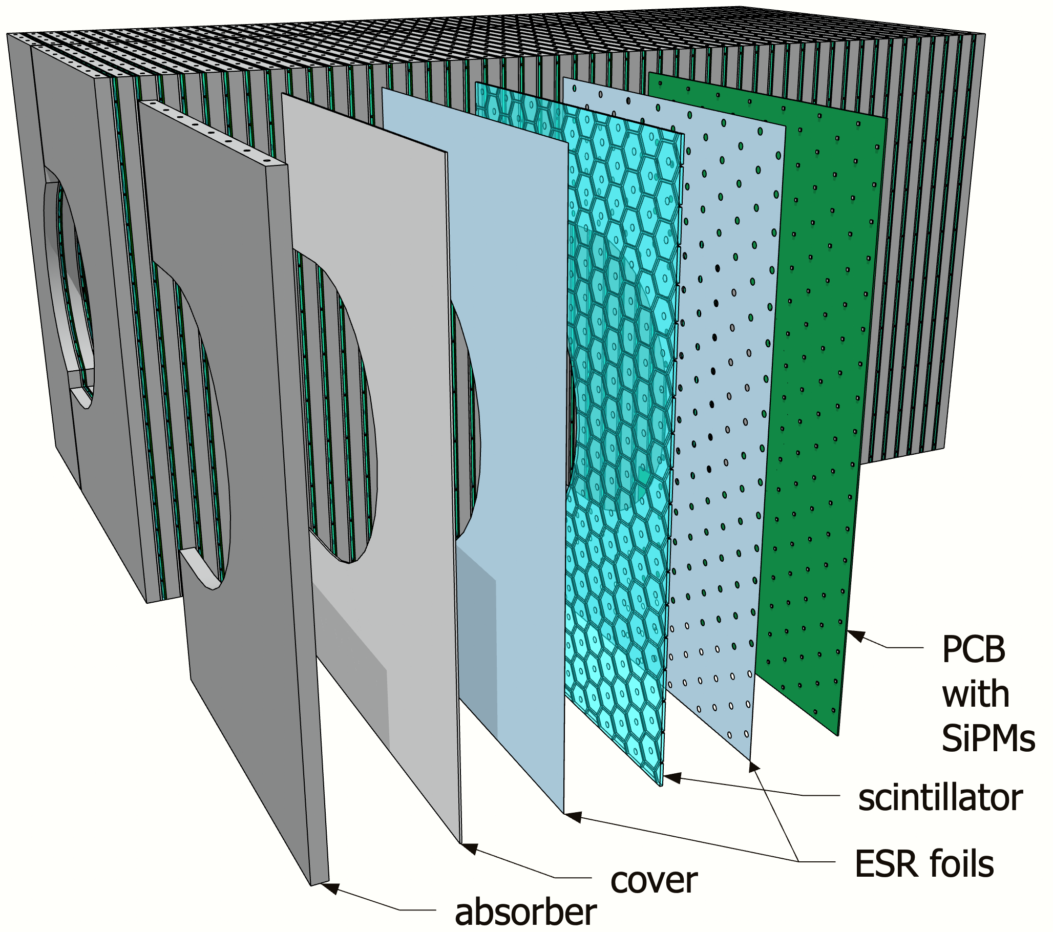

The HG-CALI is divided into two sets of layers with different absorber materials. In the first, tungsten is used; in the second, high-strength steel is used. The use of tungsten is motivated for two reasons: first, it allows for a compensated design; second, its lower radiation length and nuclear-interaction lengths compared to steel ( 0.35 cm, = 9.95 cm for W and 1.76 cm, = 16.8 cm for Fe) helps in reducing leakage of the core of hadronic showers to the beampipe.
The use of magnetic steel is required to contain magnetic-field flux. The EIC poses a strict requirement on fringe fields, mainly driven by the need of accurate polarization of the beams. The amount of steel required in this region is still under study and no formal requirement has been established. We have assumed a total thickness of 33.81 cm of steel (the last 21 layers) for the simulations presented in Sec. 3.
2.3 Scintillator cells
A single scintillator “megatile” is used for each half-layer, which has a slightly different shape to match the corresponding absorber shape. The scintillator panels are tessellated with hexagonal cells defined by grooves.
Each cell will have a dimple in its center above the SiPMs that are hosted on the PCB. The grooves are filled with a mixture of epoxy and titanium dioxide pigment, following procedures similar to the STAR electromagnetic calorimeter STAR:2002ymp. An alternative could be to paint the cells’ edges with reflective paint, such as Saint Gobain BC-621. The latter approach was used in the CMS HCAL CERN-LHCC-97-031.
To fully tessellate each layer, some of the cells on the edges will be cropped or extended. This is not necessarily an issue given that the design allows for a cell-to-cell calibration based on minimum-ionizing particles.
The megatile is covered on the front and back with reflective foil like the VM2000 enhanced specular reflector (ESR) to increase the light yield and to improve uniformity across the cell area. The ESR foil on the downstream side of the megatiles will include holes for the dimples in each cell. The ESR foil will not be wrapped to facilitate assembly; instead, the edges of the scintillator megatiles will be painted.


The dimples in the center of each cell will have the same dimensions used in the CMS HGCAL test beam Belloni:2021kcw, which define a spherical dome with a radius of curvature of 3.8 mm and a depth of 1.6 mm, as shown in Fig. 6. The dimples improve signal uniformity across the area of the cell by alleviating hot-spot effects near the SiPM Blazey:2009zz, Simon:2010hf.
The megatile concept has several advantages over a design in which each tile is wrapped individually, such as the ones used in the CALICE prototype CALICE:2010fpb and the CMS HGCAL CERN-LHCC-2017-023, especially for a small and complicated geometry such as that of HG-CALI. The megatile design would simplify assembly and reduce cell-to-cell variations caused by wrapping with ESR foil deSilva:2020mak.
Previous experience with calorimeters that use megatiles such as the STAR electromagnetic calorimeter STAR:2002ymp suggest that optical cross-talk can be reduced to about 2 when using a mixture of epoxy and titanium dioxide to fill the grooves that define the cells. This level of optical crosstalk is acceptable for this application, given that hadronic showers encompass a large number of hits over a wide area.
The megatile concept provides us with the flexibility to define the transverse granularity of the detector, and thus optimize it. We envision that the area of these cells will vary from layer to layer, for example as shown in Fig. 7, with finer granularity in the furthest upstream layers and coarser granularity in the downstream. The granularity is yet to be optimized, but we estimate that a reasonable choice would yield a total of less than 5k channels.

Test-beam results by the CMS HGCAL collaboration Belloni:2021kcw showed that the light yield of 3 mm thick scintillator cells (Eljen Technology EJ-200) is about 32 photo-electrons for 9 cm2 cells; about 26 photo-electrons for 12 cm2 cells, and about 20 photoelectrons for 36 cm2 cells.
2.4 Silicon photo-multipliers
Both the CALICE and CMS collaborations use 1.31.3 mm2 SiPMs Belloni:2021kcw, CERN-LHCC-2017-023. Larger-area SIPMs were considered, e.g., by Jiang et al. in the context of RD for the CEPC Jiang:2020rhv. Unlike the applications for ILC or CEPC, which will use millions of channels, or the CMS HGCAL, which uses about 200k channels, our design will have just a few thousand channels. Therefore, the total cost of SiPM would still be reasonable even if we choose models with larger areas.
We anticipate that larger area SiPMs will make the calorimeter more robust against non-uniformity created by SiPM misalignment deSilva:2020mak, as well as saturation effects. The photoelectron yield increases linearly with the area of the SiPM, so choosing a 9 mm2 SiPM could increase the light yield by roughly a factor of 4.5 with respect to the CMS HGCAL Belloni:2021kcw.
As we will show in Sec. 3, the maximum hit energy reaches MeV or 250 MIPs. We anticipate an operation for 60 photo-electrons per MIP for the cm2 cells. This high light yield would create a buffer to cover for the reduced signal-to-noise ratio after radiation damage.
The Hamamatsu model S14160-3025 has about 40k pixels, which translates into a dynamic range of more than 670 MIPs, so no saturation effect is expected for cm2 cells.
The neutron fluence expected at the EIC near the insert region will not exceed neutrons/cm2 per year from the electron-proton collisions at the top luminosity cm-2s AbdulKhalek:2021gbh. The corresponding ionizing radiation dose is 25 Gy per year.
The expected SiPM radiation damage would be classified as “modest” in Garutti’s review Garutti:2018hfu on the topic. It would mainly lead to increased dark current that can affect the ability to identify single-photon peaks. This level of damage can partially be recovered with annealing Garutti:2018hfu, which could be done after each run (as explained in Sec. 2.6).
For reference, CMS uses SiPM-on-tile technology for regions where the total dose is less than 3000 Gy and fluences less than 81013 /cm2, although the SiPMs will be operated at 30 C to reduce the impact of the increased noise CERN-LHCC-2017-023.
The STAR experiment at RHIC is currently operating a steel-scintillator calorimeter readout with SiPMs Tsai:2015bna that is expected to receive fluences that are similar to those expected at the EIC. Detailed data on radiation-induced noise taken with STAR will guide future iterations of the HG-CALI design.
2.5 SiPM-carrying boards and backplane board
The SiPMs will be hosted in a PCB with no active elements. The PCB will also host LEDs next to each SiPM in the dimple area to be used for monitoring and calibration purposes, similarly to the CMS HGCAL design CERN-LHCC-2017-023. The SiPM-carrying board will host a high-density connector to connect to the backplane board. The SiPMs will not be actively cooled.
On either side of the insert are 4 mm PCB backplanes used for readout, which the PCB for each scintillator assemblies connect into like a traditional crate. Figure 8 shows the location of the PCB backplanes.

The SiPM-carrying boards will be plugged in and unplugged one-at-a-time during assembly and maintenance. The backplane board will also be used to power the SiPMs and control the LED system for calibration and monitoring.
2.6 Accessibility for maintenance
The scintillator assemblies could be removed for maintenance by sliding them out laterally from between the absorbers when the HCal is opened, as illustrated in Fig. 9. This will be possible because the interaction point will have a rail system that will be integrated to the support structure AbdulKhalek:2021gbh.


This feature ensures that the SiPMs boards could be annealed at high-temperature after each run to minimize radiation damage, and that SiPMs and scintillator tiles could be replaced.
2.7 Geometric acceptance
The overall effects of the EIC crossing angle and other beam parameters are discussed in Ref. crossangle_1. Events in the lab frame, where the beams have a non-zero crossing angle, can be Lorentz transformed into a frame where the beams are anti-parallel and have energies very close to those in the lab frame. This “minimally-transformed, collinear frame” is a natural choice to extract many physics observables and the accompanying particles’ angular distributions.
In the hadron- (electron-) going direction, scattering angles defined in the lab frame relative to the hadron (electron) beam will be equivalent to the scattering angle in the minimally-transformed collinear frame crossangle_2. In particular, for a detector in the hadron-going direction, its angular acceptance should be defined relative to the hadron beam.
To estimate the geometrical acceptance of the insert, we determined where cones of constant (that is, pseudorapidity with respect to the axis – the proton beam axis) would intersect the detector. Figure 10 shows projections of these cones superimposed on a (vertical vs. longitudinal) cross-section of the insert. Within this slice, the cone skims the inner edge of the detector, while those at lower hit the face of the detector.
To determine the geometrical acceptance over the full azimuthal range we projected these cones of constant onto the faces of the scintillators planes of the insert, resulting in elliptical rings of constant . An example is shown in the inset of Fig. 11 for =3.7, which covers the full azimuthal acceptance on all layers of the detector.
We show in Fig. 11 the cross sections of these cones for several values of at the first layer (top left panel), one of the middle layers (top right panel), and the last layer (bottom left panel). While there is some acceptance up to , this is limited to one side of the detector, and it barely skims the first layer, causing a degradation of the signal, as we quantify in Sec. 3.
Since the final detector design may differ from the baseline design presented in this work, we discuss possible alternatives: with a clearance parameter of 3 cm instead of 4 cm, the entire ring fits entirely within the first scintillator layer. If the clearance parameter were increased to 5 cm, the full ring would still be within the acceptance of the detector, but it would come very close to the edge, resulting in some degradation.
The relevant scale to compare various clearance options has to be the effective radiation length of the insert, which in our design is minimized using mostly tungsten as an absorber. This is because the relevant metric is whether or not the core of the hadronic showers can be well contained, as we describe more in Sec. 3.
Given that even seemingly small differences of clearance definitions can have a large impact in extending the coverage of the detector, careful engineering design and studies are required to minimize the clearance as much as possible.
2.8 Total calorimeter thickness
We determined the amount of material (in nuclear interaction lengths, ) that a particle travelling in a straight line would pass through in the HG-CALI and the beampipe as modeled in Ref. beampipe, as a function of its polar angle with respect to the axis. We averaged this with respect to the azimuthal angle and show the results in the left panel of Fig. 12.
The HG-CALI covers polar angles from about 2∘ to 6∘, with up to about 7 nuclear interaction lengths. Between 3∘ and 6∘, there is overlap between the HG-CALI and the HCal endcap. The HCal endcap has a somewhat lower number of nuclear interaction lengths (about 6) than the insert. There is a small amount of material traversed by particles passing through the sides of the beampipe (about 1), which may allow the detection of showering at very small .
We show in the right panel of Fig. 12 the dependence of the amount of material traversed in the HCal insert on and . The amount of material is nearly uniform in in the range. Since the insert’s outer shape is (approximately) a square, the value of at the edge of the insert depends non-trivially on . At about (depending on ) particles may skim the edge of the insert, creating a signal in both the insert and the HCal. Particles with encounter at least two nuclear interaction lengths of material in the insert at all azimuthal angles.
The HG-CALI can complement the HCal endcap at angles where the effective thickness is not maximal by providing a measurement of the shower-start position and incident-particle angle, both of which will be better measured in the insert.
3 Simulation and performance
3.1 Geometry and simulation setup with DD4HEP
We used the DD4HEP framework Frank:2014zya to define the geometry and ran the Geant4 framework GEANT4:2002zbu to evaluate the performance of the HG-CALI. The version of Geant4 used is 10.7.p03.
Table 1 shows the materials, thicknesses, and numbers of interaction lengths for each component of a single layer of the insert (see Fig. 5). The previously described layer design is followed: 30 layers W/Sc, 20 layers steel/Sc, and 1 final layer of steel.
For simplicity, the granularity of the insert was assumed to be 33 cm2 for all the layers. Additionally, the model did not include the dimples and grooves in the scintillator layers, nor the SiPMs in the PCB. The model included a realistic beampipe geometry and material description beampipe.
We also included in the simulation an HCal model similar to the STAR/ATHENA design Tsai:2015bna, ATHENA, assuming a granularity of 1010 cm2, 20 mm thick absorbers, and 3 mm thick scintillators.
| Material | density | thickness | |
| (g/cm3) | (cm) | ||
| Absorber (tungsten) | 19.3 | 1.61 | 0.15566 |
| Absorber (steel) | 7.85 | 1.61 | 0.09364 |
| Air | 0.0012 | 0.02 | |
| Aluminum | 2.699 | 0.20 | 0.00502 |
| ESR | 1.06 | 0.015 | 0.00022 |
| Scintillator | 1.06 | 0.30 | 0.00436 |
| ESR | 1.06 | 0.015 | 0.00022 |
| PCB | 1.86 | 0.16 | 0.00352 |
| Air | 0.0012 | 0.02 | |
| Total (tungsten) | – | 2.34 | 0.16899 |
| Total (steel) | – | 2.34 | 0.10697 |
The solenoidal magnetic field is expected to be low in the forward region relevant for the insert, but is not precisely known at this time so it was not included in the simulation.
For the simulation of the particle shower in the material, we used the FTFP_BERT_HP physics list of Geant4, which well describes the CALICE test-beam data CALICE:2015fpv, including the time evolution of hadronic showers in both tungsten and steel absorbers CALICE:2014tgv. To model saturation effects in the scintillator response we applied Birks’ law Birks:1951boa with a constant 0.126 mm/MeV.
The particle origin position was assumed to be at and the first layer of the HCal insert was placed at mm.
No noise was included in the simulation, as a realistic implementation is not available at this time, but its effect was accounted for with an energy threshold as described in the next section. For the digitization step, a 12-bit dynamic range for the ADC and maximum value set to 200 MeV.
Each cell was assigned a timestamp dictated by the particle with the earliest time of arrival to the cell. The effect of the time resolution was included as a cell-by-cell smearing with a Gaussian with , 1 ns. Unlike in Ref. CALICE:2015fpv, no SiPM-saturation effect was simulated since this effect is expected to be negligible with the model chosen as baseline22 2 For reference, the SiPM used in the CALICE W-AHCAL prototype contained about 1k channels whereas the one used in our design has 14.4k channels..
The hits were also required to have , where is the most-probable energy deposited by a minimum-ionizing particle (MIP), which is about 0.8 MeV as obtained from simulations of high-energy muons. This energy cut was assumed to reduce the noise to a negligible level, as it will correspond to a cut of about 6 photoelectrons. Our selection was more relaxed than the CALICE studies CALICE:2010fpb that used an older generation of SiPMs with significantly larger noise, after-pulsing, and cross-talk.
We used a time cut of ns, where is defined when the generated particle hit the front of the insert. As we will show in Sec. 3.4, this selection yields a compensated response with a basic reconstruction algorithm. Much larger integration times might be possible given the EIC bunch structure and absence of pileup. Such time information can be exploited with advanced algorithms, such as those proposed in Refs. Graf:2022lwa, Akchurin:2021afn, Qasim:2021hex.
3.2 Shower-shape examples


Figure 13 shows some example shower shapes for a 50 GeV with and a random . As expected, the showers can be roughly described as having a narrow core from electromagnetic sub-showers and a halo from hadronic sub-showers. The core typically contains cells with large energy deposits, whereas the halo is composed of mainly low-energy cells. The latter are dominated by the copious production of neutrons produced in tungsten. Similar observations have been made with CALICE prototypes Sefkow:2015hna.
The hadronic-shower shapes, although irregular, provide a hint on the performance of the insert. The production of neutrons, which drives the hadronic halo, occurs over wide angles. Some of the neutrons will be emitted in the direction of the beampipe hole, but often these appear in the other side of the calorimeter instead of being lost altogether. On the other hand, the core of the shower is electromagnetic in nature so its size is driven by the radiation length, which is short in tungsten.
3.3 Hit distributions
Figure 14 shows the hit-energy and multiplicity distributions for a 50 GeV with . We show the distributions separately for all hits above the 0.1 MIP threshold, all hits that have more energy than the average of all the hits in their respective showers, and those with more than 5 MIPs of energy.
The average hit energy was found to be about 1.6 MeV, with 17% of the hits containing energy above 1.6 MeV and 7.6% containing energy above 5 MIPs (4 MeV). The maximum hit energy was about 200 MeV. The hits-per-shower distribution shows a broad peak around 275 hits, whereas the hits above average show a narrower distribution centered around 50 hits, and those above 5 MIPs show an average of 20 hits.
3.4 Linearity for hadrons and electrons and ratio
Figure 15 shows the energy distributions of showers at = 3.7 both for and with various energies. The total reconstructed energy was computed as:
| (1) |
where and are the sum of hit energies in the insert and HCal respectively, and and are the sampling fractions for the insert and HCal, respectively. The sampling fraction is computed by taking the ratio of the output energy to the input energy in the calorimeter. The sampling fraction is 0.9 for the insert and 2.2 for the HCal.
The response for pions in the insert is mostly Gaussian but it shows a low-energy tail, which is much less pronounced with the combined measurement using the HCal insert and the HCal (this is quantified in Sec. 3.5). This suggests that the low-energy tail is due to leakage in the transverse direction from the HCal insert towards the HCal.
The response for electrons is mostly Gaussian. This also suggests that that the electromagnetic core of the hadronic showers is well contained due to short radiation length of tungsten.
Figure 16 shows the mean energy deposited in the HCal insert for electrons and pions, along with the ratio, which is found to be about 0.97 on average.
3.5 Non-Gaussian tails due to leakage
Leakage is quantified as the fraction of events in which the shower energy is below , where and are obtained from the Gaussian fit to the distribution. Figure 17 shows the leakage for and at different energies and =3.7. The leakage in the insert alone for is about 10% for the entire energy range but relatively small (about 1% or lower) for electrons. After considering both the HCal and the HCal insert, the leakage for showers drops to about , suggesting most of the leakage at =3.7 is in the transverse direction with a minimal amount of it leaking through the beampipe. This indicates that neutrons, which are produced over a large solid angle, traverse the hole and are measured rather than being lost in the small solid angle of the beampipe exit (as illustrated in Fig. 13).
3.6 Single-hadron energy resolution
Figure 18 shows that the resolution, defined as ratio of the width () to the mean value of the fitted energy distribution, for charged pions at =3.7. The HCal insert meets the requirements set in the EIC Yellow Report AbdulKhalek:2021gbh, even beyond the pseudorapidity range for which it was set.
The expected resolution for the HG-CALI is similar to the CALICE test-beam data CALICE:2015fpv. We have also implemented the CALICE geometry in DD4HEP for both the steel and tungsten prototypes and were able to reproduce the linearity and the resolutions reported in Ref. CALICE:2015fpv to within 10, indicating that the similarity that we see in Fig. 18 is not coincidental.
3.7 Pseudorapidity dependence of performance
Figure 19 shows the distribution of shower energies at a constant pion energy of 50 GeV but with different . The measured distributions using both the HCal insert and HCal can be well described by a Gaussian fit, but the fit quality deteriorates with increasing . For 3.9, the fraction of events in the low-energy tail increases due to losses to the beampipe hole. This stems from the worse geometrical acceptance of the HCal insert here (see Sec. 2.7).
Figure 20 shows the leakage for 50 GeV and at different . Taking both the HCal endcap and the HCal insert into account removes most of the leakage, which is in the transverse direction and can be recovered, as shown by solid markers. At the high the leakage increases sharply but is still only about 5 at for and about 2 for .
Figure 21 shows the energy resolutions obtained with the HCal insert and the HCal as a function of for 50 GeV . The resolution obtained with HG-CALI only is constant at about over the region and it degrades at lower and higher . Including the HCal improves the resolution only at low but not at high . The horizontal line represents the EIC Yellow Report requirement AbdulKhalek:2021gbh, which is defined up to , beyond which only “degraded performance” is specified. The HG-CALI resolution meets the YR requirement up to , and gets slightly worse at the highest region due to the poorer acceptance as discussed in Sec. 2.7.
4 Summary and conclusions
We have presented a design for a high-granularity calorimeter insert (HG-CALI) for the forward hadronic calorimeter of the EIC detector. Its sampling design is based on the CALICE “SiPM-on-tile” concept and uses scintillator megatiles that are grooved to define hexagonal cells. Each layer is distinctly shaped to adapt to the conical beampipe shape that accommodates a beam-crossing angle of 25 mrad.
The HG-CALI represents the first concrete proposal to instrument the range, which is challenging due to the EIC crossing angle. It offers an optimal acceptance coverage that is limited only by the clearance from the beampipe. It thus represents a way to maximize acceptance up to nearly , which is a key requirement set in the EIC Yellow Report AbdulKhalek:2021gbh.
The HG-CALI is designed to integrate well with the rest of the endcap calorimeters and will enable easy access to the scintillator layers and SiPMs for maintenance and upgrades. Such a feature will enable frequent annealing of the SiPMs, which will keep radiation damage within manageable levels.
The energy resolution of the HG-CALI meets the EIC Yellow Report requirements even with a basic reconstruction algorithm. Moreover, this device will provide 5D shower information (energy, time, and 3D position) that can be exploited with machine-learning techniques.
The HG-CALI will complement the forward HCal in the region or so by providing an accurate estimate of the shower start position and incident angle over some range in azimuth. Such information could be used with machine-learning approaches to account for shower fluctuations and thus improve the energy resolution of the combined system.
This design will be complemented by a high-granularity electromagnetic calorimeter insert based on tungsten-powder/scintillating fiber with SiPM readout. The complete insert system will be compensated, yielding the prospect of precise and accurate measurements.
The HG-CALI has the potential to unleash the promise of imaging calorimetry at the EIC, which could support a rich physics program centered on forward jets and their substructure in polarized electron-proton and electron-nucleus collisions.
Model availability
The Google Sketchup model, as well as the CAD file in .step format, for the proposed detector can be found in Ref. sketchupModel. The DD4HEP model can be found in Ref. Milton_EIC_pEndcap_Insert_2022.
Acknowledgements
We thank members of the EIC Detector-1 proto-collaboration for useful discussions about the insert, as well as help from their Software Team on matters related to the DD4Hep framework. We thank Oskar Hartbrich for pointing out the importance of the timing cuts and the choice of resolution metric to reproduce CALICE results. We also thank Gerard Visser for feedback on the readout scheme. We also thank members of the California EIC consortium for their feedback on our design. This work was supported by MRPI program of the University of California Office of the President, award number 00010100. M.A, A.P and S.P acknowledge support from DOE grant award number DE-SC0022324. M.A, K.B, and B.K acknowledge support from DOE grant award number DE-SC0022355.
Bibliography
- [1] R. Abdul Khalek, et al., Science Requirements and Detector Concepts for the Electron-Ion Collider: EIC Yellow Report (3 2021). arXiv:2103.05419.
- [2] A. Accardi, et al., Electron Ion Collider: The Next QCD Frontier: Understanding the glue that binds us all, Eur. Phys. J. A 52 (9) (2016) 268. arXiv:1212.1701, doi:10.1140/epja/i2016-16268-9.
- [3]
ATHENA Collaboration, ATHENA
Detector Proposal - A Totally Hermetic Electron Nucleus Apparatus proposed
for IP6 at the Electron-Ion Collider (Dec. 2021).
doi:10.5281/zenodo.6539707.
URL https://doi.org/10.5281/zenodo.6539707 - [4] ECCE consortium, EIC Comprehensive Chromodynamics Experiment Collaboration Detector Proposal (May 2022). doi:10.5281/zenodo.6537588.
- [5] J. K. Adkins, et al., Design of the ECCE Detector for the Electron Ion Collider (9 2022). arXiv:2209.02580.
- [6] J. Arrington, et al., EIC Physics from An All-Silicon Tracking Detector (2 2021). arXiv:2102.08337.
- [7] R. Abdul Khalek, et al., Snowmass 2021 White Paper: Electron Ion Collider for High Energy Physics, in: 2022 Snowmass Summer Study, 2022. arXiv:2203.13199.
- [8] F. Sefkow, A. White, K. Kawagoe, R. Pöschl, J. Repond, Experimental Tests of Particle Flow Calorimetry, Rev. Mod. Phys. 88 (2016) 015003. arXiv:1507.05893, doi:10.1103/RevModPhys.88.015003.
- [9] M. A. Thomson, Particle Flow Calorimetry and the PandoraPFA Algorithm, Nucl. Instrum. Meth. A 611 (2009) 25–40. arXiv:0907.3577, doi:10.1016/j.nima.2009.09.009.
- [10] The Phase-2 Upgrade of the CMS Endcap Calorimeter, Tech. rep., CERN, Geneva (Nov 2017). doi:10.17181/CERN.IV8M.1JY2.
- [11] H. Abramowicz, et al., International Large Detector: Interim Design Report (3 2020). arXiv:2003.01116.
- [12] A. C. Abusleme Hoffman, et al., Detector Technologies for CLIC 1/2019 (5 2019). arXiv:1905.02520, doi:10.23731/CYRM-2019-001.
- [13] M. Dong, et al., CEPC Conceptual Design Report: Volume 2 - Physics & Detector (11 2018). arXiv:1811.10545.
- [14] L. Li, Q. Shan, W. Jia, B. Yu, Y. Liu, Y. Shi, T. Hu, J. Jiang, Optimization of the CEPC-AHCAL scintillator detector cells, JINST 16 (03) (2021) P03001. doi:10.1088/1748-0221/16/03/P03001.
- [15] Y. Duan, et al., Scintillator tile batch test of CEPC AHCAL, JINST 17 (05) (2022) P05006. arXiv:2111.03660, doi:10.1088/1748-0221/17/05/P05006.
- [16] F. Simon, Silicon photomultipliers in particle and nuclear physics, Nucl. Instrum. Meth. A 926 (2019) 85–100. arXiv:1811.03877, doi:10.1016/j.nima.2018.11.042.
- [17] G. Blazey, et al., Directly Coupled Tiles as Elements of a Scintillator Calorimeter with MPPC Readout, Nucl. Instrum. Meth. A 605 (2009) 277–281. doi:10.1016/j.nima.2009.03.253.
- [18] F. Simon, C. Soldner, Uniformity Studies of Scintillator Tiles directly coupled to SiPMs for Imaging Calorimetry, Nucl. Instrum. Meth. A 620 (2010) 196–201. arXiv:1001.4665, doi:10.1016/j.nima.2010.03.142.
- [19] V. Andreev, et al., A high granularity scintillator hadronic-calorimeter with SiPM readout for a linear collider detector, Nucl. Instrum. Meth. A 540 (2005) 368–380. doi:10.1016/j.nima.2004.12.002.
- [20] V. Andreev, et al., A high-granularity plastic scintillator tile hadronic calorimeter with APD readout for a linear collider detector, Nucl. Instrum. Meth. A 564 (2006) 144–154. doi:10.1016/j.nima.2006.04.044.
- [21] C. Adloff, et al., Construction and Commissioning of the CALICE Analog Hadron Calorimeter Prototype, JINST 5 (2010) P05004. arXiv:1003.2662, doi:10.1088/1748-0221/5/05/P05004.
- [22] F. Simon, C. Soldner, Uniformity studies of scintillator tiles directly coupled to SiPMs for imaging calorimetry, Nuclear Instruments and Methods in Physics Research Section A: Accelerators, Spectrometers, Detectors and Associated Equipment 620 (2-3) (2010) 196–201. doi:10.1016/j.nima.2010.03.142.
- [23] M. Feickert, B. Nachman, A Living Review of Machine Learning for Particle Physics (2 2021). arXiv:2102.02770.
- [24] M. Paganini, L. de Oliveira, B. Nachman, CaloGAN : Simulating 3D high energy particle showers in multilayer electromagnetic calorimeters with generative adversarial networks, Phys. Rev. D 97 (1) (2018) 014021. arXiv:1712.10321, doi:10.1103/PhysRevD.97.014021.
- [25] M. Paganini, L. de Oliveira, B. Nachman, Accelerating Science with Generative Adversarial Networks: An Application to 3D Particle Showers in Multilayer Calorimeters, Phys. Rev. Lett. 120 (4) (2018) 042003. arXiv:1705.02355, doi:10.1103/PhysRevLett.120.042003.
- [26] D. Belayneh, et al., Calorimetry with deep learning: particle simulation and reconstruction for collider physics, Eur. Phys. J. C 80 (7) (2020) 688. arXiv:1912.06794, doi:10.1140/epjc/s10052-020-8251-9.
- [27] S. R. Qasim, J. Kieseler, Y. Iiyama, M. Pierini, Learning representations of irregular particle-detector geometry with distance-weighted graph networks, Eur. Phys. J. C 79 (7) (2019) 608. arXiv:1902.07987, doi:10.1140/epjc/s10052-019-7113-9.
- [28] F. A. Di Bello, S. Ganguly, E. Gross, M. Kado, M. Pitt, L. Santi, J. Shlomi, Towards a Computer Vision Particle Flow, Eur. Phys. J. C 81 (2) (2021) 107. arXiv:2003.08863, doi:10.1140/epjc/s10052-021-08897-0.
- [29] E. Buhmann, S. Diefenbacher, E. Eren, F. Gaede, G. Kasieczka, A. Korol, K. Krüger, Getting High: High Fidelity Simulation of High Granularity Calorimeters with High Speed, Comput. Softw. Big Sci. 5 (1) (2021) 13. arXiv:2005.05334, doi:10.1007/s41781-021-00056-0.
- [30] N. Akchurin, C. Cowden, J. Damgov, A. Hussain, S. Kunori, On the use of neural networks for energy reconstruction in high-granularity calorimeters, JINST 16 (12) (2021) P12036. arXiv:2107.10207, doi:10.1088/1748-0221/16/12/P12036.
- [31] J. Pata, J. Duarte, J.-R. Vlimant, M. Pierini, M. Spiropulu, MLPF: Efficient machine-learned particle-flow reconstruction using graph neural networks, Eur. Phys. J. C 81 (5) (2021) 381. arXiv:2101.08578, doi:10.1140/epjc/s10052-021-09158-w.
- [32] C. Neubüser, J. Kieseler, P. Lujan, Optimising longitudinal and lateral calorimeter granularity for software compensation in hadronic showers using deep neural networks, Eur. Phys. J. C 82 (1) (2022) 92. arXiv:2101.08150, doi:10.1140/epjc/s10052-022-10031-7.
- [33] N. Akchurin, C. Cowden, J. Damgov, A. Hussain, S. Kunori, Perspectives on the Calibration of CNN Energy Reconstruction in Highly Granular Calorimeters (8 2021). arXiv:2108.10963.
- [34] E. Buhmann, S. Diefenbacher, D. Hundhausen, G. Kasieczka, W. Korcari, E. Eren, F. Gaede, K. Krüger, P. McKeown, L. Rustige, Hadrons, better, faster, stronger, Mach. Learn. Sci. Tech. 3 (2) (2022) 025014. arXiv:2112.09709, doi:10.1088/2632-2153/ac7848.
- [35] G. R. Khattak, S. Vallecorsa, F. Carminati, G. M. Khan, Fast simulation of a high granularity calorimeter by generative adversarial networks, Eur. Phys. J. C 82 (4) (2022) 386. arXiv:2109.07388, doi:10.1140/epjc/s10052-022-10258-4.
- [36] M. Chadeeva, S. Korpachev, Machine-learning-based prediction of parameters of secondaries in hadronic showers using calorimetric observables (5 2022). arXiv:2205.12534.
- [37] S. R. Qasim, N. Chernyavskaya, J. Kieseler, K. Long, O. Viazlo, M. Pierini, R. Nawaz, End-to-end multi-particle reconstruction in high occupancy imaging calorimeters with graph neural networks (4 2022). arXiv:2204.01681.
- [38] V. Mikuni, B. Nachman, Score-based Generative Models for Calorimeter Shower Simulation (6 2022). arXiv:2206.11898.
- [39] J. Repond, Detector Concepts of the Electron-Ion Collider, PoS High-pT2019 (2020) 015. doi:10.22323/1.355.0015.
- [40]
CORE Proto-Collaboration, CORE
- a COmpact detectoR for the EIC (Dec. 2021).
doi:10.5281/zenodo.6536630.
URL https://doi.org/10.5281/zenodo.6536630 - [41] F. Bock, et al., Design and Simulated Performance of Calorimetry Systems for the ECCE Detector at the Electron Ion Collider (7 2022). arXiv:2207.09437.
- [42] U. Behrens, et al., Test of the ZEUS Forward Calorimeter Prototype, Nucl. Instrum. Meth. A 289 (1990) 115–138. doi:10.1016/0168-9002(90)90253-3.
- [43] B. Andrieu, et al., The H1 liquid argon calorimeter system, Nucl. Instrum. Meth. A 336 (1993) 460–498. doi:10.1016/0168-9002(93)91257-N.
- [44] C. Adloff, et al., Electromagnetic response of a highly granular hadronic calorimeter, JINST 6 (2011) P04003. arXiv:1012.4343, doi:10.1088/1748-0221/6/04/P04003.
- [45] C. Adloff, J. Blaha, J. J. Blaising, C. Drancourt, A. Espargiliere, R. Galione, N. Geffroy, Y. Karyotakis, J. Prast, G. Vouters, Tests of a particle flow algorithm with CALICE test beam data, JINST 6 (2011) P07005. arXiv:1105.3417, doi:10.1088/1748-0221/6/07/P07005.
- [46] C. Adloff, et al., Hadronic energy resolution of a highly granular scintillator-steel hadron calorimeter using software compensation techniques, JINST 7 (2012) P09017. arXiv:1207.4210, doi:10.1088/1748-0221/7/09/P09017.
- [47] F. Simon, C. Soldner, L. Weuste, T3B — an experiment to measure the time structure of hadronic showers, JINST 8 (2013) P12001. arXiv:1309.6143, doi:10.1088/1748-0221/8/12/P12001.
- [48] C. Adloff, et al., Track segments in hadronic showers in a highly granular scintillator-steel hadron calorimeter, JINST 8 (2013) P09001. arXiv:1305.7027, doi:10.1088/1748-0221/8/09/P09001.
- [49] C. Adloff, et al., Validation of GEANT4 Monte Carlo Models with a Highly Granular Scintillator-Steel Hadron Calorimeter, JINST 8 (2013) 07005. arXiv:1306.3037, doi:10.1088/1748-0221/8/07/P07005.
- [50] C. Adloff, et al., The Time Structure of Hadronic Showers in highly granular Calorimeters with Tungsten and Steel Absorbers, JINST 9 (2014) P07022. arXiv:1404.6454, doi:10.1088/1748-0221/9/07/P07022.
- [51] B. Bilki, et al., Pion and proton showers in the CALICE scintillator-steel analogue hadron calorimeter, JINST 10 (04) (2015) P04014. arXiv:1412.2653, doi:10.1088/1748-0221/10/04/P04014.
- [52] M. Chefdeville, et al., Shower development of particles with momenta from 15 GeV to 150 GeV in the CALICE scintillator-tungsten hadronic calorimeter, JINST 10 (12) (2015) P12006. arXiv:1509.00617, doi:10.1088/1748-0221/10/12/P12006.
- [53] G. Eigen, et al., Hadron shower decomposition in the highly granular CALICE analogue hadron calorimeter, JINST 11 (06) (2016) P06013. arXiv:1602.08578, doi:10.1088/1748-0221/11/06/P06013.
- [54] J. Repond, et al., Hadronic Energy Resolution of a Combined High Granularity Scintillator Calorimeter System, JINST 13 (12) (2018) P12022. arXiv:1809.03909, doi:10.1088/1748-0221/13/12/P12022.
- [55] F. Sefkow, F. Simon, A highly granular SiPM-on-tile calorimeter prototype, J. Phys. Conf. Ser. 1162 (1) (2019) 012012. arXiv:1808.09281, doi:10.1088/1742-6596/1162/1/012012.
- [56] O. D. Tsai, et al., Results of R&D on a new construction technique for W/ScFi calorimeters, J. Phys. Conf. Ser. 404 (2012) 012023. doi:10.1088/1742-6596/404/1/012023.
- [57] O. D. Tsai, et al., Development of a forward calorimeter system for the STAR experiment, J. Phys. Conf. Ser. 587 (1) (2015) 012053. doi:10.1088/1742-6596/587/1/012053.
- [58] E.-C. Aschenauer, et al., The RHIC Cold QCD Plan for 2017 to 2023: A Portal to the EIC (2 2016). arXiv:1602.03922.
- [59] EIC Detector Managerie: Step file for the detector chamber, https://physdiv.jlab.org/EIC/Menagerie/CAD/Beam%20Pipe/Detector%20chamber%20210222.stp.
- [60]
EICUG, Maximizing the scientific
output of the eic (Apr. 2022).
doi:10.5281/zenodo.6422182.
URL https://doi.org/10.5281/zenodo.6422182 - [61] R. Alarcon, et al., CORE – a COmpact detectoR for the EIC (9 2022). arXiv:2209.00496.
- [62] D. P. Anderle, et al., Electron-ion collider in China, Front. Phys. (Beijing) 16 (6) (2021) 64701. arXiv:2102.09222, doi:10.1007/s11467-021-1062-0.
- [63] M. Beddo, et al., The STAR barrel electromagnetic calorimeter, Nucl. Instrum. Meth. A 499 (2003) 725–739. doi:10.1016/S0168-9002(02)01970-8.
- [64] The CMS hadron calorimeter project: Technical Design Report, Technical design report. CMS, CERN, Geneva, 1997.
- [65] A. Belloni, et al., Test beam study of SiPM-on-tile configurations, JINST 16 (07) (2021) P07022. arXiv:2102.08499, doi:10.1088/1748-0221/16/07/P07022.
- [66] L. M. S. de Silva, F. Simon, Effects of misalignment on response uniformity of SiPM-on-tile technology for highly granular calorimeters, JINST 15 (06) (2020) P06030. arXiv:2004.05066, doi:10.1088/1748-0221/15/06/P06030.
- [67] J. Jiang, S. Zhao, Y. Niu, Y. Shi, Y. Liu, D. Han, T. Hu, B. Yu, Study of SiPM for CEPC-AHCAL, Nucl. Instrum. Meth. A 980 (2020) 164481. doi:10.1016/j.nima.2020.164481.
- [68] E. Garutti, Y. Musienko, Radiation damage of SiPMs, Nucl. Instrum. Meth. A 926 (2019) 69–84. arXiv:1809.06361, doi:10.1016/j.nima.2018.10.191.
- [69]
J. Adam, et al., Accelerator and
beam conditions critical for physics and detector simulations for the
Electron-Ion Collider (2021).
doi:10.5281/zenodo.6514605.
URL https://doi.org/10.5281/zenodo.6514605 - [70]
B. Schmookler, et al., High
electron-proton elastic scattering at the future Electron-Ion Collider
(2022).
doi:10.48550/ARXIV.2207.04378.
URL https://arxiv.org/abs/2207.04378 - [71] M. Frank, F. Gaede, C. Grefe, P. Mato, DD4hep: A Detector Description Toolkit for High Energy Physics Experiments, J. Phys. Conf. Ser. 513 (2014) 022010. doi:10.1088/1742-6596/513/2/022010.
- [72] S. Agostinelli, et al., GEANT4–a simulation toolkit, Nucl. Instrum. Meth. A 506 (2003) 250–303. doi:10.1016/S0168-9002(03)01368-8.
- [73] J. B. Birks, Scintillations from Organic Crystals: Specific Fluorescence and Relative Response to Different Radiations, Proc. Phys. Soc. A 64 (1951) 874–877. doi:10.1088/0370-1298/64/10/303.
- [74] C. Graf, F. Simon, Time-assisted energy reconstruction in a highly-granular hadronic calorimeter (3 2022). arXiv:2203.01317.
- [75] S. R. Qasim, K. Long, J. Kieseler, M. Pierini, R. Nawaz, Multi-particle reconstruction in the High Granularity Calorimeter using object condensation and graph neural networks, EPJ Web Conf. 251 (2021) 03072. arXiv:2106.01832, doi:10.1051/epjconf/202125103072.
- [76]
S. J. Paul, M. Arratia, O. Tsai,
Model for a Calorimeter Insert
for the Electron-Ion Collider (7 2022).
doi:10.5281/zenodo.6950495.
URL https://doi.org/10.5281/zenodo.6950495 - [77]
R. Milton, B. Schmookler, Z. Ji, B. Karki, S. Paul, M. Arratia,
EIC pEndcap Insert in DD4hep
(7 2022).
doi:10.5281/zenodo.6836014.
URL https://doi.org/10.5281/zenodo.6836014