Compact single-seed, module-based laser system on a transportable high-precision atomic gravimeterPreprint: APS/123-QED
Abstract
A single-seed, module-based compact laser system is demonstrated on a transportable -based high-precision atomic gravimeter. All the required laser frequencies for the atom interferometry are provided by free-space acousto-optic modulators (AOMs) and resonant electro-optic phase modulators (EOMs). The optical phase-locked loop between the two optical paths derived from the same laser provides an easy frequency manipulation between two laser frequencies separated by the hyperfine frequency of 6.835 GHz using an AOM and an EOM, respectively. Our scheme avoids parasite Raman transitions present in the direct EOM modulation scheme (modulating directly at the frequency of the hyperfine splitting), which have detrimental effects on the accuracy of the gravity measurements. The optical phase-locked loop also provides a convenient way for vibration compensation through the Raman lasers’ phase offset. Furthermore, the modular design approach allows plug-and-play nature on each individual optic module and also increases the mechanical stability of the optical systems. We demonstrate high-precision gravity measurements with 17.8 stability over 250 seconds averaging time and 2.5 stability over 2 h averaging time.
I Introduction
Atomic (quantum) gravimeters measure acceleration of free-falling atomic test masses by using matter-wave interferometry Peters, Chung, and Chu 2001; Geiger et al. 2020. Such gravimeters have demonstrated comparable performance to its classical counterpart (absolute gravimeter using free-falling corner cube Niebauer et al. 1995) in terms of sensitivity, long-term stability and accuracy Freier et al. 2016; Gillot et al. 2014. Due to its ability to carry out continuous and long-term absolute gravity measurements (not possible by free-falling corner cube gravimeters due to mechanical wear during each drop of measurement), great development efforts are currently being dedicated to transform atomic gravimeters from lab-based instruments into field-capable or on-board devices Ménoret et al. 2018; Bidel et al. 2018.
The laser system for alkali-based atomic gravimeters usually requires at least two master lasers in order to address the atomic hyperfine transitions that are few GHz apart Hu et al. 2013; Ménoret et al. 2011; Lévèque et al. 2014; Zhang et al. 2018. The master laser remains one of the most delicate systems within atomic interferometry experiments, especially when implementing vibration compensation via an optical phase-locked loop of the two Raman lasers Merlet et al. 2009; Lautier et al. 2014; Le Gouët et al. 2008. Hence, reducing the number of master lasers would greatly reduce the complexity of the experiments. A fiber-based single-seed laser system operating at wavelength and down converted to nm wavelength using frequency doubling (periodically poled lithium niobate crystal) has been realized Theron et al. 2015. Single-seed laser systems operating directly at the desired wavelength for atoms Fang et al. 2018 and Cesium atoms Wu et al. 2017 have also been developed. All of the above-mentioned experiments using single-seed laser generate Raman frequency pairs by directly modulating the EOM at the frequency of the hyperfine splitting. The infinite pairs of EOM carrier and sideband frequencies having the same frequency difference inevitably induce parasite Raman transitions that reduce the accuracy of the gravimeter measurements Carraz et al. 2012.
In this work, we demonstrate a module-based free-space laser system with a single nm wavelength master laser, addressing 87Rb atoms and offer flexibility in replacing/re-designing the optical systems. The cooling and repumper laser frequencies are generated by modulating the EOM at 6.58 GHz. The +1 sideband of the EOM modulation also serves as the higher-frequency Raman laser, while the lower-frequency Raman laser is generated by a double-pass acousto-optic modulator (AOM) having detuning of MHz. This configuration results in a sole pair of Raman lasers with frequency separation of 6.83 GHz, thus avoiding the parasite Raman transitions such as in Theron et al. 2015; Fang et al. 2018; Wu et al. 2017. The optical phase-locked system between the two Raman lasers offers a feedback mechanism for vibration compensation via the Raman lasers’ phase offset. It also provides an easier Raman frequency manipulation at low frequency carrier (via AOM at 123 MHz) instead of manipulation at high carrier frequency of 6.83 GHz.
II Laser System
II.1 Optical distribution


We place all of the electronic and optical components that serve the same function into separate aluminum enclosures (modules), see Figures 1 and 2. For example, the temperature and current controllers for the master laser are grouped together with the laser itself into a single module. Different modules are interconnected via polarization-maintaining optical fibers. This modular arrangement results in stand-alone packages, such as the master laser module, the optical amplifier module and the spectroscopy module. The modular design allows for re-arrangement of the optical paths, as well as modification to individual modules without affecting the others, providing a high degree of re-configurability.
All the laser frequencies are derived from a single interference-filter-stabilized external-cavity diode laser (ECDL, linewidth 100 kHz) module Baillard et al. 2006; Gilowski et al. 2007. The influence of the master laser phase noise on the sensitivity of retro-reflected atom interferometers can be found in Le Gouët et al. 2007. Three tapered (optical) amplifier (TA) modules Zappala et al. 2014 are employed to obtain the desired laser intensity (Thorlabs TPA780P20). Different laser frequencies are provided by two resonant electro-optic phase modulators (EOMs; QUBIG GmbH) and nine acousto-optic modulators (AOM; AA Opto Electronic).
II.2 Module-based design
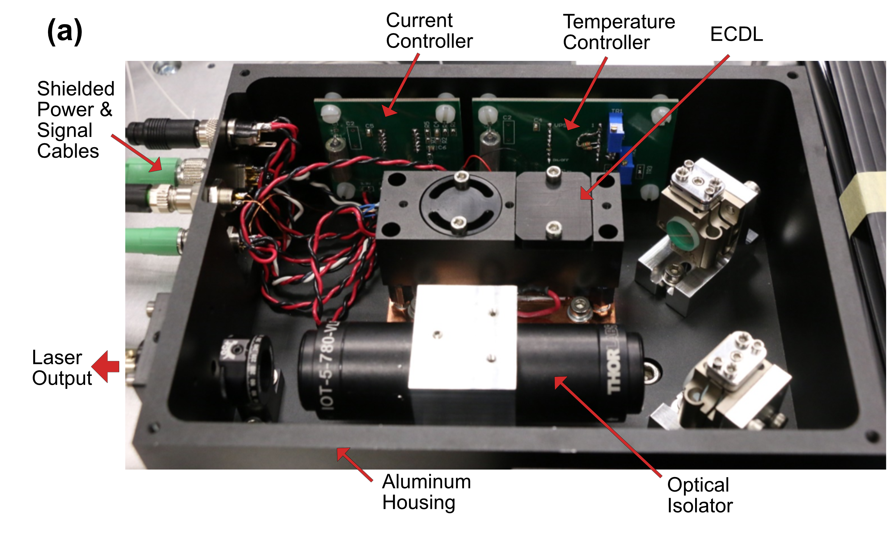
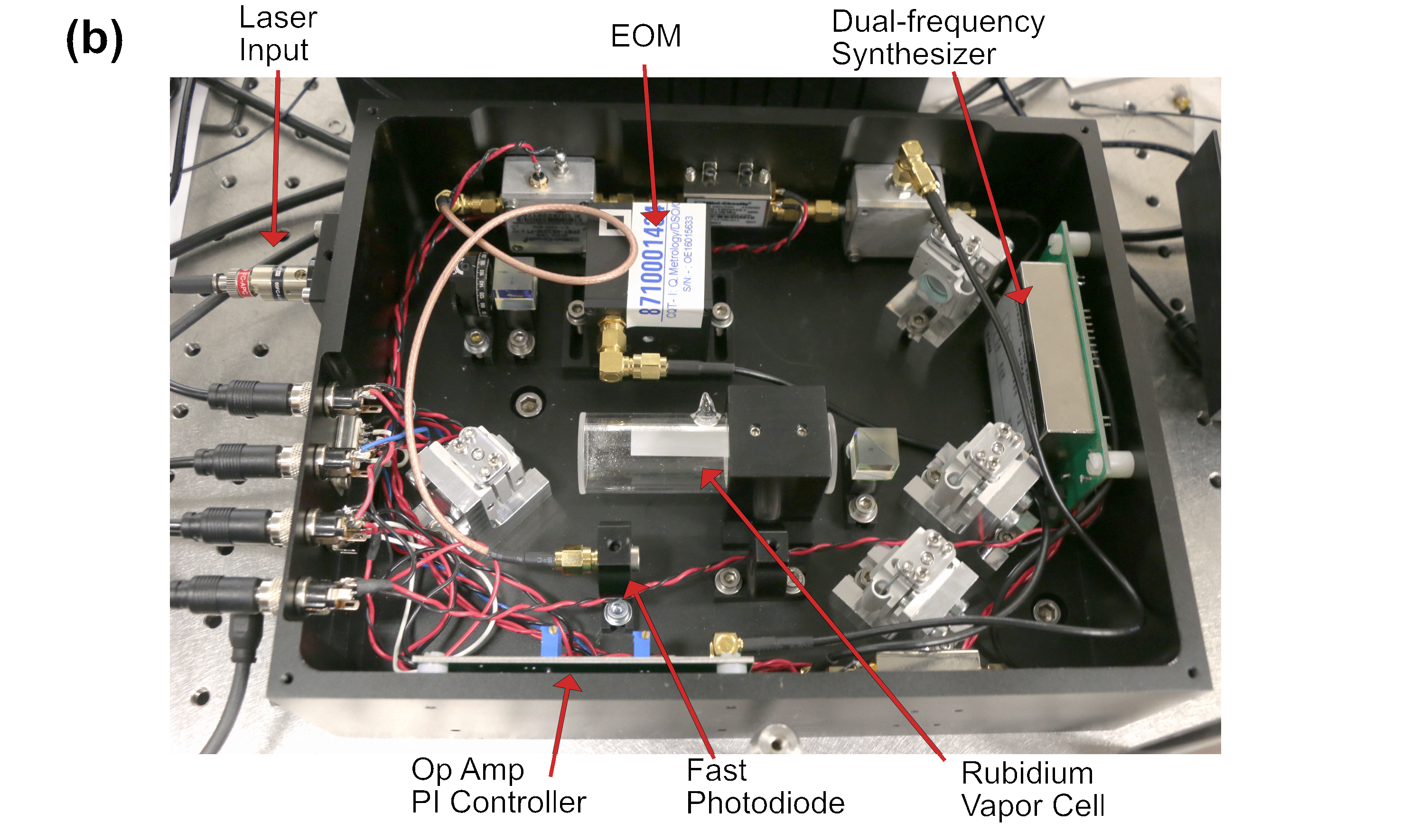

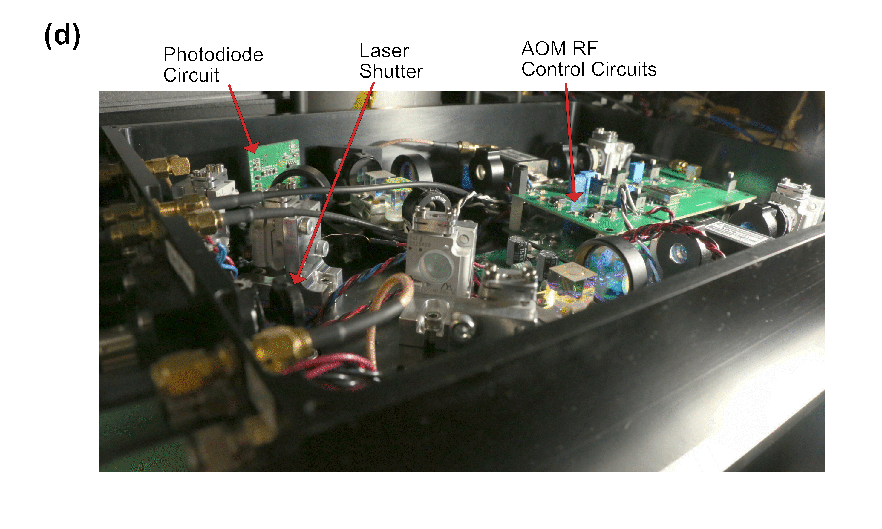
Figure 2 shows the actual photos of our atomic gravimeter’s optic modules. Each module’s enclosure is cut out from a single piece of aluminum, with total height of mm, base thickness of mm and laser beam height maintained at mm. The modules are designed to be air-tight to prevent air disturbances and accumulation of dust. To ensure long-term mechanical stability of the laser beams, we employ flexure type mirror holders (Siskiyou, IXF.50ta) and compact fiber couplers (Schäfter+Kirchhoff GmbH, 60FC). The mechanical stability of the laser beams are further improved due to the fact that the optical paths are truncated into individual modules interconnected by optical fibers. Each module is controlled externally by a computer via shielded electrical cables. We showcase the schematic design of the imaging beam and push beam pertaining to the AOM module in Figure 3. We have not observed misalignment of the optical elements by transporting the gravimeter within the building.

III Frequency control
III.1 EOM module
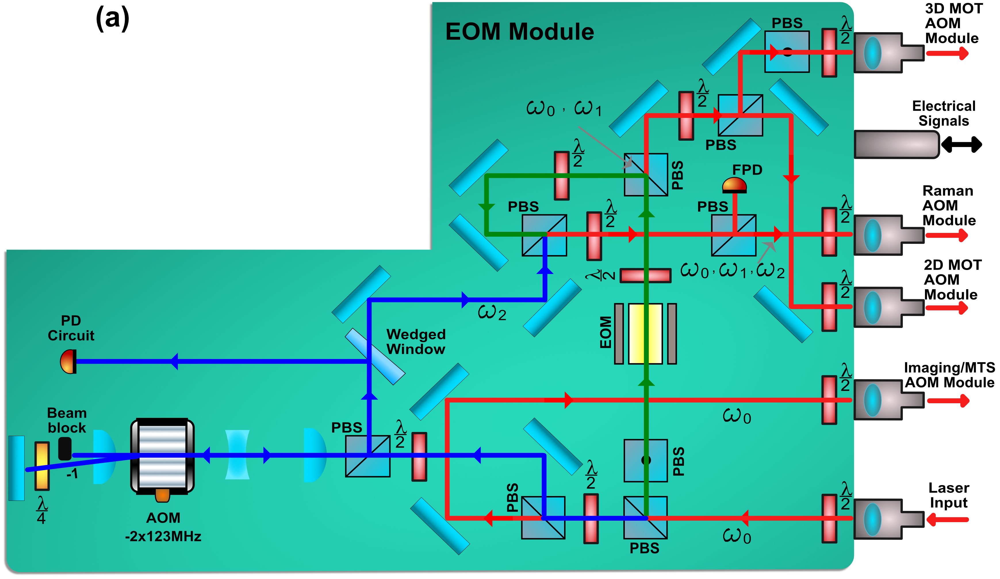

During the free fall of the atomic test masses, in this case rubidium-87 atoms, the acceleration of the atoms is interrogated by the counter-propagating Raman lasers. The frequency difference between the two counter-propagating Raman lasers ( 6.8 GHz) are chirped to compensate the induced Doppler shift of the falling atoms due to gravitational acceleration, which is around MHz/s at 1 g. This chirping rate is served as the “optical ruler” of the gravity measurements where the gravitational acceleration can be approximated as Peters, Chung, and Chu 2001, where is the frequency chirping rate and nm is the effective wavelength of the Raman lasers.
In order to attain a measurement precision of , the frequency precision of the Raman lasers’ driving frequency has to be maintained at least at the same level, Freier 2017, where GHz. Direct chirping of GHz frequency at sub-Hz precision for a duration of s can be technically challenging. In this work, the Raman laser frequency difference is driven by two separate frequency synthesizers, namely, a synthesizer (NI, QuickSyn Lite Synthesizer) driving the high frequency side of the Raman lasers (, 6.58 GHz) and a direct digital synthesizer (DDS, AD9854) driving the low frequency side of the Raman lasers (, 123 MHz), see Figure 4. The frequency chirping is provided by the AD9854 via a double-pass AOM during the interferometry sequence, ensuring deterministic frequency shifting and micro-second time steps Karcher, Dos Santos, and Merlet 2020. The intensity ratio between the Raman lasers is easily adjusted via the half-wave plate and polarization beamsplitter pair (which overlaps the two laser beams) in order to minimize the differential AC Stark shift of the laser transitions Olbertz 2011.
III.2 Optical phase-locked loop and frequency chain


All the frequencies in the gravimeter are referenced to a 10 MHz rubidium frequency standard (Stanford Research Systems, PRS10), Figure 5a. Because the Raman lasers and travel two separate paths, an unwanted phase shift can be induced by mechanical vibrations, thermal drifts and air current disturbances. To maintain a fixed phase difference between the Raman lasers during the interferometry sequences, the beat frequency between and ( MHz) after being recombined into the same polarization is immediately recorded by a fast photodiode (Hamamatsu Photonics, G4176-03) and then phase locked with the frequency output of the AD9854, Figure 5b. This enforces a phase locked condition between and since and travel the same path. The optical phase-locked loop also provides a convenient feedback path for vibration compensation through Raman lasers’ phase offset (Section IV.1). Because both of the Raman lasers are derived from a single ECDL, the optical phase-locked loop only requires a single slow feedback path (instead of an additional fast feedback path for wider locking bandwidth Yim et al. 2014), Figure 5c.
The overall frequency of the Raman lasers is further detuned by a double-pass AOM with MHz detuning, resulting in a laser power of approximately 18 mW for and 9 mW for into the atoms. Together with a collimated Raman laser beam diameter of 20 mm, we have a pulse duration 34 . The authors would like to bring the attention of the readers that amplifying the Raman lasers intensity by seeding it into another TA would generate unwanted sidebands due to intensity modulation between the two close laser frequencies and Ferrari et al. 1999. This is not a problem for the cooling laser in which and are GHz apart. If additional laser power is required for the Raman lasers, the carrier can be filtered out by a Fabry-Pérot cavity before overlapping with and subsequently amplified by the TA, as was carried out by Li et al. 2017. Alternatively, the carrier can be nulled by increasing the power of EOM’s RF amplifier. All of these methods would require phase locking at 6.8 GHz instead of MHz as is carried out by this work.
III.3 Timing sequences

The driving frequencies and the driving amplitudes of the EOMs need to be adjusted during different stages of the experiment sequence (Figure 6). These are especially crucial for avoiding un-intended atomic transitions due to the multi-frequencies EOM’s output. We briefly discuss the procedure as follow:
- 1.
Atom loading: Only a small amount of repumper laser intensity is needed during magneto-optical trap (MOT) loading stage. Therefore, the driving amplitude of the 6.58 GHz-resonant EOM (EOM1) is lowered down such that +1 sideband to carrier intensity ratio is %. We typically load atoms into the 3D MOT in s.
- 2.
Launching: The upward traveling cooling lasers are blue-detuned 3.2 MHz while the downward traveling cooling lasers are red-detuned 3.2 MHz for about 1.5 ms so that the atomic cloud is launched upwards to form an atomic fountain Peters, Chung, and Chu 2001 trajectory (detailed experiment procedures please refer to Oon 2021). By decreasing the overall cooling laser frequency and intensity (far-detuned molasses Salomon et al. 1990), the atomic cloud is further cooled to 3 . At the end of the launching procedure, EOM1’s driving frequency is shifted to 6.642 GHz, so that the Repumper laser (+1 sideband) is resonant with while the cooling laser (carrier) is off-resonant to the atomic transition. This is to ensure that the atoms are pumped into F=2 hyperfine state.
- 3.
State selection: A second EOM (EOM2) with the driving frequency of 6.856 GHz, producing a horizontal, linear polarized beam and simultaneous resonant transitions of and , pumps the atoms into magnetic insensitive state , Figure 1b. The atoms subsequently undergo two velocity selection + blow-away sequences: A first Raman pulse transfers the atoms from the to state, followed by a resonant light (produced by an un-modulated laser light) that blows away atoms that are remaining at the state. A second Raman pulse transfers the atoms back to state, and followed by a resonant light (produced by +1 sideband of EOM2, with driving frequency shifted to 6.869 GHz to avoid coupling of the carrier to atomic transitions) that blows away atoms that are remaining at state. This results in a narrow velocity spread of the atoms of nK in the vertical axis. Approximately 85 % of the atoms are lost through the velocity-selection sequences, this corresponds to atoms for the interferometer.
- 4.
Interferometry: A matter-wave Mach-Zehnder interferometry of is performed on the atomic fountain, with as long as 200 ms. EOM1’s driving frequency is shifted to 6.58 GHz, and its driving amplitude is increased such that the +1 sideband to the carrier intensity ratio is 40%. The driving frequency and amplitude are maintained throughout the interferometry sequence, producing a fixed Raman laser . The chirping of the Raman laser () is then provided by linear sweeping a double-pass AOM via AD9854. The intensity ratio between and is varied via a half waveplate and polarizing beamsplitter (PBS) pair to minimize the differential AC Stark shift. A further mitigation of systematic errors due to the AC Stark shifts and residual magnetic field can be achieved by alternating the sign of the frequency chirping during every alternative measurement cycle.
- 5.
State-selective detection: The falling atomic cloud first goes through a horizontal (circular-polarized) retro-reflecting light sheet near resonance at , emitting fluorescent light proportional to the population of atoms at the state; most of the atoms at the state are lost due to thermal expansion from the imaging lights. The remaining falling atoms go through a second light sheet (vertically separated by 22 mm) having the same frequency but with a small portion of repumping light provided by EOM1, the atoms then emit fluorescent light proportional to the population of atoms at state, thus enabling state-selective detection.
IV Performance
IV.1 Vibration compensation through Raman lasers’ phase offset

Vibration noise remains one of the pressing challenges for precision transportable absolute gravimeters in noisy environments. In our experiment, the Raman lasers are retro-reflected vertically by a mirror. The mirror serves as a “gravity reference”, as any vibrations incurred on the mirror will inevitably imprint on the interferometer. The vibrations of the retro-reflecting mirror have to be either actively cancelled Hensley, Peters, and Chu 1999; Oon and Dumke 2022 or by means of post processing Le Gouët et al. 2008 in order to minimize the inertial influence on the gravitational acceleration measurements.
To demonstrate the ability of mitigating the effect of vibrations through Raman lasers’ phase offset, we create an artificial excitation on the passive isolation platform (where the Raman lasers’ retro-reflecting mirror is placed) through voice coil actuators (please refer to our previous work on the detail of the vibration isolation setup Oon and Dumke 2022). At Raman separation time of ms, the presence of excitation at 0.95 Hz with amplitude of g would render the interferometric fringe unrecognizable during Raman lasers’ frequency scanning, as shown in Figure 7 (top). We then go through the same frequency scanning, but the vibration signals are recorded via an accelerometer (Nanometrics, Titan) during the three-pulse Mach-Zehnder interferometry, and the vibration induced phase shift () is then compensated at the third Raman’s pulse via the recursive function,
| (1) |
where is the acceleration of the retro-reflecting mirror at -th iterative loop, sampling time and is the triangular shape transfer function symmetric around the end of second Raman pulse (t=0) Lautier et al. 2014; Geiger et al. 2011 with and . Interferometric fringe is restored by feeding the output into the offset of the optical phase-locked loop, Figure 7 (bottom). A sine fit to the center fringe shows a resolution of 12.4 ( g) after an integration time of 100 s, despite under the presence of a g vibration excitation.
IV.2 Gravity measurements

| Averaging time | 250 s | 2 h |
|---|---|---|
| Active vibration isolation | 17.8 | 2.5 |
| Phase compensation | 18.0 | 5.1 |
| Passive isolation | 27.5 | 7.0 |
Figure 8 shows continuous gravity measurements under three different scenarios, namely, (1) with active vibration isolation where the Raman’s retro-reflecting mirror is actively stabilized by voice coil actuators Oon and Dumke 2022, (2) vibration compensation via Raman lasers’ phase offset and (3) with only passive vibration isolation (Minus K Technology, 25BM-10). The standard deviations of the three gravity measurements with both averaging time of 250 s and 2 h are shown in Table 1.

It is worth noting that the temperature of the accelerometer (Nanometrics, Titan) has to be well stabilized (within C) to avoid feedback of the thermal noise signals onto the gravity measurements. To further reduce the thermal noise, a 0.001 Hz digital high-pass filter is employed on the accelerometer signal output when implementing active vibration isolation (a 0.008 Hz high-pass filter when implementing the Raman lasers’ phase compensation). Vibration cancelation using the Raman lasers’ phase compensation is prone to the influence of the accelerometer signal bias; the integration of the acceleration signals drifting from zero volt can render significant oscillations on the gravitational measurements, as evidenced by the Allan deviations of the measurements, Figure 9. Further reduction of such an effect will be addressed in future work Le Gouët et al. 2008. Active vibration isolation is less sensitive to the slow frequency feedback compared to using phase compensation, this is due to the fact that the frequency response of the passive isolation stage to the force produced by the voice coil actuator has an additional high-pass characteristic at low frequency ( for and for , where is the resonant frequency of the passive isolation stage ) Hensley, Peters, and Chu 1999; Oon 2021; Freier 2010.
V Conclusions
We have demonstrated a compact single-seed laser system on a transportable high-precision 87Rb-based atomic gravimeter that reaches measurement stability of 2.5 with averaging time of 2 h. The optical phase-locked loop derived from a single-seed laser provides a convenient way for Raman laser frequency chirping and vibration compensation through Raman lasers’ phase offset. Frequency generation using a mixture of an AOM and a EOM helps in alleviating detrimental effects on the accuracy of the gravity measurements due to parasite Raman transitions. The modular design of the optical systems ensures its mechanical stability during transportation as well as plug-and-play capability of the individual optic modules (provided that the same optical fiber is used). All these features offer a valuable approach for the construction of future in-field atomic gravimeters as well as other atomic technologies.
Acknowledgements.
The authors thank Christoph Hufnagel, Nathan Shetell, Kaisheng Lee and Koon Siang Gan for their careful reading of their manuscript and their many insightful comments and suggestions. This work is supported by the National Research Foundation (Singapore) under the Quantum Engineering Program, DSO National Laboratories (Singapore) and the Ministry of Education of Singapore.AUTHOR DECLARATIONS
Conflict of interest
The authors have no conflicts to disclose.
DATA AVAILABILITY
The data that support the findings of this study are available from the corresponding author upon reasonable request.
References
- Peters, Chung, and Chu (2001) A. Peters, K. Y. Chung, and S. Chu, “High-precision gravity measurements using atom interferometry,” Metrologia 38, 25 (2001).
- Geiger et al. (2020) R. Geiger, A. Landragin, S. Merlet, and F. Pereira Dos Santos, “High-accuracy inertial measurements with cold-atom sensors,” AVS Quantum Science 2, 024702 (2020).
- Niebauer et al. (1995) T. Niebauer, G. Sasagawa, J. E. Faller, R. Hilt, and F. Klopping, “A new generation of absolute gravimeters,” Metrologia 32, 159 (1995).
- Freier et al. (2016) C. Freier, M. Hauth, V. Schkolnik, B. Leykauf, M. Schilling, H. Wziontek, H.-G. Scherneck, J. Müller, and A. Peters, “Mobile quantum gravity sensor with unprecedented stability,” in Journal of Physics: Conference Series, Vol. 723 (IOP Publishing, 2016) p. 012050.
- Gillot et al. (2014) P. Gillot, O. Francis, A. Landragin, F. P. Dos Santos, and S. Merlet, “Stability comparison of two absolute gravimeters: optical versus atomic interferometers,” Metrologia 51, L15 (2014).
- Ménoret et al. (2018) V. Ménoret, P. Vermeulen, N. Le Moigne, S. Bonvalot, P. Bouyer, A. Landragin, and B. Desruelle, “Gravity measurements below g with a transportable absolute quantum gravimeter,” Scientific reports 8, 1–11 (2018).
- Bidel et al. (2018) Y. Bidel, N. Zahzam, C. Blanchard, A. Bonnin, M. Cadoret, A. Bresson, D. Rouxel, and M. Lequentrec-Lalancette, “Absolute marine gravimetry with matter-wave interferometry,” Nature communications 9, 1–9 (2018).
- Hu et al. (2013) Z.-K. Hu, B.-L. Sun, X.-C. Duan, M.-K. Zhou, L.-L. Chen, S. Zhan, Q.-Z. Zhang, and J. Luo, “Demonstration of an ultrahigh-sensitivity atom-interferometry absolute gravimeter,” Physical Review A 88, 043610 (2013).
- Ménoret et al. (2011) V. Ménoret, R. Geiger, G. Stern, N. Zahzam, B. Battelier, A. Bresson, A. Landragin, and P. Bouyer, “Dual-wavelength laser source for onboard atom interferometry,” Optics Letters 36, 4128–4130 (2011).
- Lévèque et al. (2014) T. Lévèque, L. Antoni-Micollier, B. Faure, and J. Berthon, “A laser setup for rubidium cooling dedicated to space applications,” Applied Physics B 116, 997–1004 (2014).
- Zhang et al. (2018) X. Zhang, J. Zhong, B. Tang, X. Chen, L. Zhu, P. Huang, J. Wang, and M. Zhan, “Compact portable laser system for mobile cold atom gravimeters,” Applied Optics 57, 6545–6551 (2018).
- Merlet et al. (2009) S. Merlet, J. Le Gouët, Q. Bodart, A. Clairon, A. Landragin, F. P. Dos Santos, and P. Rouchon, “Operating an atom interferometer beyond its linear range,” Metrologia 46, 87 (2009).
- Lautier et al. (2014) J. Lautier, L. Volodimer, T. Hardin, S. Merlet, M. Lours, F. Pereira Dos Santos, and A. Landragin, “Hybridizing matter-wave and classical accelerometers,” Applied Physics Letters 105, 144102 (2014).
- Le Gouët et al. (2008) J. Le Gouët, T. Mehlstäubler, J. Kim, S. Merlet, A. Clairon, A. Landragin, and F. Pereira Dos Santos, “Limits to the sensitivity of a low noise compact atomic gravimeter,” Applied Physics B 92, 133–144 (2008).
- Theron et al. (2015) F. Theron, O. Carraz, G. Renon, N. Zahzam, Y. Bidel, M. Cadoret, and A. Bresson, “Narrow linewidth single laser source system for onboard atom interferometry,” Applied Physics B 118, 1–5 (2015).
- Fang et al. (2018) J. Fang, J. Hu, X. Chen, H. Zhu, L. Zhou, J. Zhong, J. Wang, and M. Zhan, “Realization of a compact one-seed laser system for atom interferometer-based gravimeters,” Optics Express 26, 1586–1596 (2018).
- Wu et al. (2017) X. Wu, F. Zi, J. Dudley, R. J. Bilotta, P. Canoza, and H. Müller, “Multiaxis atom interferometry with a single-diode laser and a pyramidal magneto-optical trap,” Optica 4, 1545–1551 (2017).
- Carraz et al. (2012) O. Carraz, R. Charrière, M. Cadoret, N. Zahzam, Y. Bidel, and A. Bresson, “Phase shift in an atom interferometer induced by the additional laser lines of a raman laser generated by modulation,” Physical Review A 86, 033605 (2012).
- McCarron, King, and Cornish (2008) D. McCarron, S. King, and S. Cornish, “Modulation transfer spectroscopy in atomic rubidium,” Measurement science and technology 19, 105601 (2008).
- Baillard et al. (2006) X. Baillard, A. Gauguet, S. Bize, P. Lemonde, P. Laurent, A. Clairon, and P. Rosenbusch, “Interference-filter-stabilized external-cavity diode lasers,” Optics Communications 266, 609–613 (2006).
- Gilowski et al. (2007) M. Gilowski, C. Schubert, M. Zaiser, W. Herr, T. Wübbena, T. Wendrich, T. Müller, E. Rasel, and W. Ertmer, “Narrow bandwidth interference filter-stabilized diode laser systems for the manipulation of neutral atoms,” Optics Communications 280, 443–447 (2007).
- Le Gouët et al. (2007) J. Le Gouët, P. Cheinet, J. Kim, D. Holleville, A. Clairon, A. Landragin, and F. Pereira Dos Santos, “Influence of lasers propagation delay on the sensitivity of atom interferometers,” The European Physical Journal D 44, 419–425 (2007).
- Zappala et al. (2014) J. Zappala, K. Bailey, Z.-T. Lu, T. O’Connor, and W. Jiang, “Note: Efficient generation of optical sidebands at ghz with a high-power tapered amplifier,” Review of Scientific Instruments 85, 046104 (2014).
- Freier (2017) C. Freier, Atom interferometry at geodetic observatories, Ph.D. thesis, Humboldt-Universität zu Berlin, Mathematisch-Naturwissenschaftliche Fakultät (2017).
- Karcher, Dos Santos, and Merlet (2020) R. Karcher, F. P. Dos Santos, and S. Merlet, “Impact of direct-digital-synthesizer finite resolution on atom gravimeters,” Physical Review A 101, 043622 (2020).
- Olbertz (2011) J.-H. Olbertz, A mobile high-precision gravimeter based on atom interferometry, Ph.D. thesis, Humboldt-Universität zu Berlin (2011).
- Yim et al. (2014) S. H. Yim, S.-B. Lee, T. Y. Kwon, and S. E. Park, “Optical phase locking of two extended-cavity diode lasers with ultra-low phase noise for atom interferometry,” Applied Physics B 115, 491–495 (2014).
- Ferrari et al. (1999) G. Ferrari, M.-O. Mewes, F. Schreck, and C. Salomon, “High-power multiple-frequency narrow-linewidth laser source based on a semiconductor tapered amplifier,” Optics Letters 24, 151–153 (1999).
- Li et al. (2017) W. Li, X. Pan, N. Song, X. Xu, and X. Lu, “A phase-locked laser system based on double direct modulation technique for atom interferometry,” Applied Physics B 123, 1–8 (2017).
- Oon (2021) F. E. Oon, A Transportable High-Precision Absolute Atomic Gravimeter, Ph.D. thesis, National University of Singapore (Singapore) (2021).
- Salomon et al. (1990) C. Salomon, J. Dalibard, W. Phillips, A. Clairon, and S. Guellati, “Laser cooling of cesium atoms below 3 k,” EPL (Europhysics Letters) 12, 683 (1990).
- Hensley, Peters, and Chu (1999) J. M. Hensley, A. Peters, and S. Chu, “Active low frequency vertical vibration isolation,” Review of scientific instruments 70, 2735–2741 (1999).
- Oon and Dumke (2022) F. E. Oon and R. Dumke, “Compact active vibration isolation and tilt stabilization for a portable high-precision atomic gravimeter,” arXiv preprint arXiv:2206.06028 (2022).
- Geiger et al. (2011) R. Geiger, V. Ménoret, G. Stern, N. Zahzam, P. Cheinet, B. Battelier, A. Villing, F. Moron, M. Lours, Y. Bidel, et al., “Detecting inertial effects with airborne matter-wave interferometry,” Nature communications 2, 1–7 (2011).
- Freier (2010) C. Freier, Measurement of local gravity using atom interferometry, Ph.D. thesis, Humboldt-Universität zu Berlin Berlin, Germany (2010).