A Dynamic Subarray Structure in Reconfigurable Intelligent Surfaces for TeraHertz Communication Systems
Abstract
Reconfigurable Intelligent Surface (RIS) has become a popular technology to improve the capability of a THz multiuser Multi-input multi-output (MIMO) communication system. THz wave characteristics, on the other hand, restrict THz beam coverage on RIS when using a uniform planar array (UPA) antenna. In this study, we propose a dynamic RIS subarray structure to improve the performance of a THz MIMO communication system. In more details, an RIS is divided into several RIS subarrays according to the number of users. Each RIS subarray is paired with a user and only reflects beams to the corresponding user. Based on the structure of RIS, we first propose a weighted minimum mean square error - RIS local search (WMMSE-LS) scheme, which requires that each RIS element has limited phase shifts. To improve the joint beamforming performance, we further develop an adaptive Block Coordinate Descent(BCD)-aided algorithm, an iterative optimization method. Numerical results demonstrate the effectiveness of the dynamic RIS subarray structure and the adaptive BCD-aided joint beamforming scheme and also show the merit of our proposed system.
Index Terms:
TeraHertz (THz), Reconfigurable Intelligent Surfaces (RIS), multiple-input-multiple-output (MIMO), Joint beamforming, Block coordinate descent (BCD), Local search (LS), weighted sum-rate (WSR)I Introduction
TeraHertz (THz) communication is becoming increasingly popular in wireless networks as a means of improving data transmission rates. THz communications provide a substantially larger capacity than millimeter wave (mmWave) and microwave communications. However, the THz wave has some shortages in practice, such as a much higher path loss, and the obstacles can easily block the line-of-sight (LOS) path. [1, 2]. As a result, the Reconfigurable Intelligent Surface (RIS) is increasingly being used in THz communications to improve the non-line-of-sight (NLOS) route [3, 4, 5, 6]. Since the RIS is a passive device with low energy consumption and without self-interference, it is regarded as a better technology than the backscatter and Multi-input multi-output (MIMO) relay [7, 8, 9, 10, 11, 12, 13, 14, 15]. In a RIS-aided THz communication system, the Base Station (BS) and users usually have a uniform planar array (UPA) antenna to improve the data transmission rates. More antennas and RIS elements also can provide a higher rate. However, when the number of UPA antennas and RIS elements increases, the system sum-rate will increase, but RIS utilization will reduce because the THz beam is more narrow and hard to cover all RIS elements.
Many existing works have tried to improve the beam coverage from BS to RIS. In [16], an ’THzPrism’ scheme was proposed to extend the angle of THz beams. The results showed that the bandwidth would lower down but still be sufficient during the increase of angular coverage. On another side, the research of [17] proposed a cross-entropy method to improve the joint beamforming performance in THz, reducing the algorithm complexity. The results showed that when the RIS elements increase with fixed BS size, the weighted sum-rate (WSR) growth rate becomes meager which means that the number of RIS elements can not grow infinitely. The authors of [18] attempted to determine the optimal number of UPA antennas and RIS components as a compromise between hardware cost, algorithm complexity, and system performance. Aside from that, beamforming is an important part of beam coverage. The beam coverage would be improved if the optimal combined beamforming between BS and RIS was near to perfect. When the number of RIS elements grows, the algorithm complexity typically grows as well [19]. In [20], the authors proposed an optimized Block coordinate descent (BCD) scheme to maximize the system sum-rate and reduce computing cost, which can counteract the impact of RIS elements increase.
In this study, we propose a dynamic RIS subarray structure in a THz MIMO system, with the number of subarrays changing in response to the number of users. Each RIS subarray only serves one corresponding user, different from the general RIS structure. To keep pace with this special structure in RIS, we first construct an environment for the RIS-aided THz system using the 3GPP standard [21]. Since the THz communications rapidly attenuates as it goes through the obstacles, the LOS path is assumed to be blocked while there is only NLOS path in direct channel [22]. In addition, both BS and users are equipped with UPA antennas, which is a tendency in THz because the active beamforming performance of UPA antennas is better than Uniform Linear Array(ULA) in same conditions [23]. In joint beamforming processing among BS, RIS, and users, we first propose a weighted minimum mean square error - RIS local search (WMMSE-LS) scheme where LS is for RIS and WMMSE is applied at BS. The number of available phase shifts of RIS is finite in the LS method, limiting RIS passive beamforming accuracy. To improve the joint beamforming performance, we propose an adapted BCD-aided algorithm, where the beamforming matrices of BS and RIS are updated iteratively with no limitation in RIS phase shifts. Simulation results demonstrate that both the dynamic RIS subarray structure and adapted BCD-aided joint beamforming can improve the performance of the RIS-aided THz communication system.
Notations: is a identity matrix. , , and denote conjugate, transpose, and conjugate transpose of matrix. is the real part of the complex number. is the imaginary part of the complex number.
II System models
In our MIMO communication system model, we mainly consider the downlink from the BS to users via the RIS or the RIS subarrays where the BS generates beams and align beams to the users to maximize the sum-rate of the network. The joint beamforming in this system includes active beamforming on BS and users, and passive on RIS/RIS subarrays.

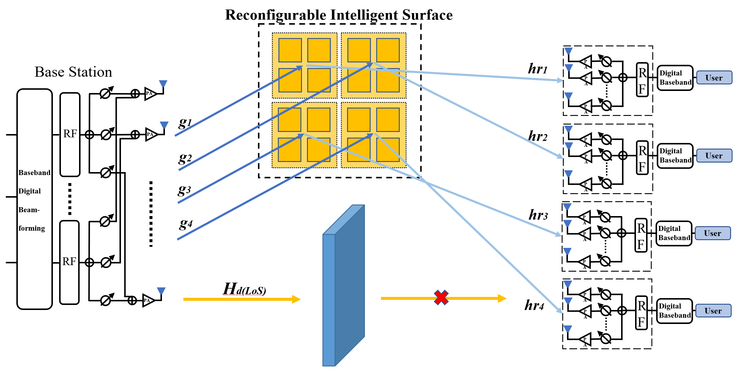
As shown in Fig. 1, there are two different RIS structures in our system model where the number of users is assumed to be 4. Fig. 1(a) indicates a system where the RIS is a general type without subarray, and Fig. 1(b) demonstrates a dynamic RIS subarray structure. In this system, the BS is equipped with UPA antenna elements, and the RIS is an array servicing users where each user has UPA antennas. There are subarrays in the dynamic RIS subarray structure, and we assume that in the proposed system. Since each user is paired with one RIS subarray, the received vector at the -th user can be expressed as:
| (1a) | |||
| (1b) |
where is the transmitting beamforming vector of BS to the -th user, is the transmission signal vector, is the phase shift matrix of the -th RIS, is the phase shift of the -th RIS element, , and is the receiving vector of the -th user. Besides, is the direct channel between BS and user without LOS path, is the channel between BS and -th RIS subarray, and is between the -th RIS subarray and the -th user. The is the additive white Gaussian noise (AWGN). The reflecting channel follows the Rician channel model according to [24], which can be expressed as:
| (2) |
| (3) |
| (4) |
| (5) |
where is the pathloss of channels and is the Rician factor, and are NLOS path components of and , respectively.
The directional vector can be expressed as:
| (6) |
where and are the angles in the respective horizontal and vertical directions, and are the numbers of elements in the horizontal and vertical directions, respectively.
III Joint beamforming scheme
The sum-rate and Signal to Interference and Noise Ratio (SINR) of the system are given below.
| (7a) | |||
| (7b) |
where is the weight of one user, which is determined by the pathloss between the BS and this user. The whole channel between the BS and the -th user is .
III-A WMMSE-LS method
The key to maximize the sum-rate is to find appropriate beamforming vectors of the BS, RIS, and users. Due to the limited computing capability and hardware complexity, the number of available vectors is finite in one system generally. We first assume that the accuracy of each RIS element’s phase shift is -bit. Each RIS element has available phase shifts, and the whole RIS has available vectors. In addition, we also presume the accuracy of users’ UPA antenna is -bit and -bit in the horizontal and vertical direction, respectively.
In order to quickly determine the beamforming vectors of RIS and users, we first propose a WMMSE-LS algorithm in this work. The phase shift of RIS elements is individually and sequentially searched. For instance, while searching the phase shift of the -th RIS element, the previous elements have been searched and fixed. The phase shift of the remaining undetermined RIS elements are randomly generated from the phase shift set. When the number of RIS components rises, the overhead of exhaustive searching becomes very substantial, necessitating the search of all possible phase shift matrices. As a result, compared to the exhaustive technique, the search space for the RIS phase shift adjustment only has to explore phase shift matrices. The set of possible phase shifts for RIS is , and the sets of angles for each user are = in the horizontal plane and = in the vertical plane.
Determining each user’s beamforming vector is the first step in this algorithm. The searching step starts from the first user and the first beamforming angle in the . While searching is ongoing, the beamforming angles of the remaining users are determined randomly. The vector of the -th user is . After the users’ beamforming vectors are determined, to simplify the algorithm description, we define an equivalent channel between BS and users, which follows that . Then RIS will search the available phase shifts, and the BS will align beams by using the WMMSE method [25]. In Algorithm 1, the WMMSE-LS joint beamforming algorithm is illustrated.
III-B Adaptive BCD-aided joint beamforming
Considering the RIS devices manufacturing, the accuracy of RIS elements is not very high generally. Despite that, the joint beamforming algorithm can be further improved without considering these limitations. In this paper, we propose an enhanced BCD aided joint beamforming method, in which the phase shift configuration of RIS elements has no accuracy limitations.
The proposed algorithm is described below. Based on the closed-form scheme in [20], the sum-rate and its maximization can be formulated as:
| (8) |
The optimization variables and can be expressed by [26]:
| (9a) | |||
| (9b) |
where . , and are temporal optimized results from last iteration. is the equivalent channel matrix generated from the previous iteration according to in this iteration.
When updating the RIS phase shift matrix , where is the -th RIS subarray which follows (1b), the phase shift of each RIS element can be generated as . is updated separately and the rest of subarray phase shifts keep fixed. When the RIS subarrays are paired with users, the dimensions of both phase shift matrices and channel matrices decrease, which greatly decrease the complexity. For instance, when updating the whole RIS in the general RIS model, the dimension of in each iteration is , the BS-RIS channel is , and the RIS-user channel is . In the RIS subarray model, each iteration only optimizes the phase shift matrix of size and the size of separate channels, and , are and . The reflecting channel is transfered as . updating follows as [27]:
| (10a) | |||
| (10b) | |||
| (10c) |
After is updated and fixed, then update on the BS. The prox-linear update rules [26] of can be expressed as:
| (11a) | |||
| (11b) |
where is the gradient matrix. follows . is the value from last iteration, and is the extrapolated point. L follows . The Algorithm 2 briefly summarizes the procedure of this scheme.
IV Numerical Results
IV-A Simulation scenario
As shown in Fig. 2, since the LOS channel between the BS and users are blocked, a RIS is deployed to assist data communications. The distance between the BS and RIS is fixed, which is set as . is used to denote the distance between the BS and the -th user while is the distance between RIS and the j-th user. The locations of users are randomly generated from a circle range, where the distance between the circle center and the RIS is set as , and the radius of the gathering zone is 20m. This communication model can be numerically presented in a cartesian coordinates system, where the BS is located at (0,0), RIS is located at (100, 0) and the center of the gathering zone is located at (100,40). The NLOS path of the direct channel follows Rayleigh fading model while the RIS reflecting cascade channel follows Rician fading, where the Rician factors in (2) and (4) are set as . The related parameters are shown in Table. I.
| Parameters | Values |
|---|---|
| BS Location | (0m,0m) |
| RIS Location | (100m,0m) |
| Carrier Frequency | 100 GHz |
| Transmission BandWidth | 10 Ghz |
| Noise power spectral density | -220 dBm/Hz |
| Path-loss for (dB) | 32.4 + 21log10() + 20log10() |
| Path-loss for (dB) | 22.4 +35.3log10()+21.3log10() |

IV-B Model parameters and results analysis

As shown in Fig. 3, when model parameters are set as , , , , , the sum-rate of the adapted BCD-aided joint beamforming is higher than that of the WMMSE-RIS local search method at the same SNR. Meanwhile, the dynamic RIS subarray structure with both adapted BCD-aided and WMMSE-RIS local search can provide a higher sum-rate than the entire RIS for joint beamforming system, which indicates that the adapted BCD algorithm has a better performance compared with the dynamic RIS subarray structure.


Fig. 4 describes the relationship between the rate and the number of iterations in the BCD optimization. As can be observed, when the transmitting SNR is 0dB, the rate increases as the number of iterations increases. Although the improvement for each user is different, the entire system still converges quickly with the RIS subarray structure. As the sum-rate improvement reaches convergence after the 50th iteration, the joint beamforming can be regarded as complete.

Fig. 5 shows the system performance against the number of RIS elements where the channel parameters remain the same. It should be noted that the number of RIS elements should be divisible by . The results reveal that the proposed RIS subarray scheme outperforms the whole RIS scheme.

Research is also conducted on the influence of the number of users against the system performance. As shown in Fig. 6, when , the WSR performance of the subarray RIS system is much better than the one for the system without it using the same joint beamforming scheme. Each RIS subarray should have the same number of reflecting antennas, and the number of users, , should be much less than .
V Conclusion
In this study, we proposed a dynamic RIS subarray structure where the subarray amount is flexible according to the number of users. Besides, a WMMSE-LS scheme with limited RIS phase shift accuracy and an adaptive BCD-aided joint beamforming approach were proposed to improve throughput performance for the investigated RIS THz system. Various system models and joint beamforming methods were compared in this research. The simulation results demonstrated that the proposed dynamic RIS subarray structure combined with the adapted BCD algorithm can improve the system performance of the RIS-aided THz MIMO communication system. In our future work, machine learning based resource allocation, such as, [28, 29], for our proposed RIS systems will be considered.
References
- [1] X. Wang, P. Wang, M. Ding, Z. Lin, F. Lin, B. Vucetic, and L. Hanzo, “Performance analysis of terahertz unmanned aerial vehicular net- works,” IEEE Transactions on Vehicular Technology, vol. 69, no. 12, pp. 16 330–16 335, 2020.
- [2] X. Wang, Z. Lin, F. Lin, and L. Hanzo, “Joint hybrid 3d beamforming relying on sensor-based training for reconfigurable intelligent surface aided terahertz-based multi-user massive mimo systems,” IEEE Sen- sors Journal, pp. 1–1, 2022.
- [3] Y. Liu, X. Liu, X. Mu, T. Hou, J. Xu, M. Di Renzo, and N. Al-Dhahir, “Reconfigurable intelligent surfaces: Principles and opportunities,” IEEE Communications Surveys & Tutorials, 2021.
- [4] M. Ding, P. Wang, D. Lopez-Peerz, G. Mao and Z. Lin, “Performance Impact of LoS and NLoS Transmissions in Dense Cellular Networks,” ,IEEE Transactions on Wireless Communications, Volume: 15, Issue: 3, March 2016. pp. 2365 – 2380.
- [5] C Liu, M Ding, C Ma, Q Li, Z Lin, YC Liang, ”Performance analysis for practical unmanned aerial vehicle networks with LoS/NLoS transmissions”, IEEE International Conference on Communications Workshops (ICC Workshops), 2018, 1-6.
- [6] D López-Pérez, M Ding, H Li, LG Giordano, G Geraci, A Garcia-Rodriguez, Z. Lin, M. Hassan, ”On the downlink performance of UAV communications in dense cellular networks”, 2018 IEEE global communications conference (GLOBECOM), 1-7
- [7] Z. Chu, P. Xiao, D. Mi, W. Hao, Z. Lin, Q. Chen, and R. Tafazolli, “Wireless powered intelligent radio environment with non-linear energy harvesting,” IEEE Internet of Things Journal, pp. 1–1, 2022.
- [8] Y. Hu, P. Wang, Z. Lin, and M. Ding, “Performance analysis of reconfigurable intelligent surface assisted wireless system with low- density parity-check code,” IEEE Communications Letters, vol. 25, no. 9, pp. 2879–2883, 2021.
- [9] Y. Hu, P. Wang, Z. Lin, M. Ding, and Y.-C. Liang, ”Performance analysis of ambient backscatter systems with ldpc-coded source signals,” IEEE Transactions on Vehicular Technology, vol. 70, no. 8, pp. 7870–7884, 2021.
- [10] Y. Chen, M. Ding, D. L opez-Perez, X. Yao, Z. Lin, and G. Mao, ”On the theoretical analysis of network-wide massive mimo performance and pilot contamination,” IEEE Transactions on Wireless Communi- cations, vol. 21, no. 2, pp. 1077–1091, 2022.
- [11] Y. Hu, P. Wang, Z. Lin, M. Ding, and Y.-C. Liang, “Machine learning based signal detection for ambient backscatter communications,” in ICC 2019 - 2019 IEEE International Conference on Communications (ICC), 2019, pp. 1–6.
- [12] S. Xing, M. Ding, and Z. Lin, “Outage capacity analysis for ambient backscatter communication systems,” in 2018 28th International Telecommunication Networks and Applications Conference (ITNAC), 2018, pp. 1–6.
- [13] Z. Lin, B. Vucetic, J. Mao, ”Ergodic capacity of LTE downlink multiuser MIMO systems”, 2008 IEEE International Conference on Communications, 3345-3349.
- [14] G. Mao, Z. Lin, X. Ge, Y. Yang, ”Towards a simple relationship to estimate the capacity of static and mobile wireless networks”, IEEE transactions on wireless communications 12 (8), 2014, 3883-3895
- [15] J. Yue, Z. Lin and B. Vucetic, ”Distributed Fountain Codes With Adaptive Unequal Error Protection in Wireless Relay Networks,” in IEEE Transactions on Wireless Communications, vol. 13, no. 8, pp. 4220-4231, Aug. 2014, doi: 10.1109/TWC.2014.2314632.
- [16] B. Zhai, Y. Zhu, A. Tang, and X. Wang, “Thzprism: Frequency- based beam spreading for terahertz communication systems,” IEEE Wireless Communications Letters, vol. 9, no. 6, pp. 897–900, 2020.
- [17] W. Chen, X. Ma, Z. Li, and N. Kuang, “Sum-rate maximization for intelligent reflecting surface based terahertz communication sys- tems,” in 2019 IEEE/CIC International Conference on Communi- cations Workshops in China (ICCC Workshops). IEEE, 2019, pp. 153–157.
- [18] J. Ge and Y.-C. Liang, “Ris-enhanced spectrum sensing: How many reflecting elements are required to achieve a detection probability close to 1?” arXiv preprint arXiv:2107.06525, 2021.
- [19] M. Z. Siddiqi, T. Mir, M. Hao, and R. MacKenzie, “Low-complexity joint active and passive beamforming for ris-aided mimo systems,” Electronics Letters, vol. 57, no. 9, pp. 384–386, 2021.
- [20] H. Guo, Y.-C. Liang, J. Chen, and E. G. Larsson, “Weighted sum-rate maximization for reconfigurable intelligent surface aided wireless networks,” IEEE Transactions on Wireless Communications, vol. 19, no. 5, pp. 3064–3076, 2020.
- [21] 3GPP, “Study on channel model for frequencies from 0.5 to 100 ghz,” 3rd Generation Partnership Project (3GPP), Tech. Rep., vol. 38, 2018.
- [22] T. Bai and R. W. Heath, “Coverage analysis for millimeter wave cellular networks with blockage effects,” in 2013 IEEE Global Conference on Signal and Information Processing. IEEE, 2013, pp. 727–730.
- [23] A. Chatterjee, S. Chatterjee, and S. S. Das, “Evaluation of spatial correlation and its effect on channel capacity of uniform planar antenna array,” in 2017 Twenty-third National Conference on Com- munications (NCC). IEEE, 2017, pp. 1–6.
- [24] Y. Han, W. Tang, S. Jin, C.-K. Wen, and X. Ma, “Large intelligent surface-assisted wireless communication exploiting statistical csi,” IEEE Transactions on Vehicular Technology, vol. 68, no. 8, pp. 8238– 8242, 2019.
- [25] Q. Shi, M. Razaviyayn, Z.-Q. Luo, and C. He, “An iteratively weighted mmse approach to distributed sum-utility maximization for a mimo interfering broadcast channel,” IEEE Transactions on Signal Processing, vol. 59, no. 9, pp. 4331–4340, 2011.
- [26] Y. Xu and W. Yin, “A block coordinate descent method for regu- larized multiconvex optimization with applications to nonnegative tensor factorization and completion,” SIAM Journal on imaging sciences, vol. 6, no. 3, pp. 1758–1789, 2013.
- [27] D. P. Bertsekas, “Nonlinear programming,” Journal of the Opera- tional Research Society, vol. 48, no. 3, pp. 334–334, 1997.
- [28] J. Leng, Z. Lin, M. Ding, P. Wang, D. Smith and B. Vucetic, ”Client Scheduling in Wireless Federated Learning Based on Channel and Learning Qualities,” in IEEE Wireless Communications Letters, vol. 11, no. 4, pp. 732-735, April 2022, doi: 10.1109/LWC.2022.3141792.
- [29] D. C. Nguyen, Q. V. Pham, P. Pathirana, M. Ding, A. Seneviratne, Z. Lin, O. dobre, W. Huang, “Federated Learning for Smart Healthcare: A Survey”, ACM Comput. Surv., Vol. 55, No. 3, Article 60 , pp.1-37, April 2023.