An elastically stabilized spherical invagination
Abstract
Invaginations are partial enclosures formed by surfaces. Typically formed by biological membranes; they abound in nature. In this paper, we consider fundamentally different structures: elastically stabilized invaginations. Focusing on spherical invaginations formed by elastic membranes, we carried out experiments and mathematical modeling to understand the stress and strain fields underlying stable structures. Friction plays a key role in stabilization, and consequently the required force balance is an inequality. Using a novel scheme, we were able to find stable solutions of the balance equations for different models of elasticity, with reasonable agreement with experiments.
Keywords: hyperelasticity, invagination, friction
1 Introduction
Invaginations are cavities with narrow openings; they are partial enclosures formed by surfaces. They abound in nature. In the process of pinocytosis [1], a cell absorbs particles - nutrients - by surrounding them with its membrane, first forming an invagination partially enclosing the particle and subsequently completely enclosing and engulfing it. Such invaginations are typically created by membranes and not by the passive partially enclosed object. Here we consider a different process, where the deformation of an elastic membrane is the result of forces exerted by a solid body resulting in an invagination entrapping the deforming body. An elastically stabilized deformation of an elastic membrane surrounding a rigid disk has already been considered [2]. Motivation for this work is to explore the effects of geometry. Here we study a spherical invagination in an elastic membrane surrounding a rigid sphere, as shown in Fig. 1, both experimentally and theoretically. We first describe our experiments in producing and characterizing spherical invaginations. We next discuss simple mathematical models and numerical simulations. We close by summarizing our findings.

2 Experiments
2.1 The membrane and the sphere
The elastic membranes used in our experiments were thin natural latex sheets sold as powder-free Crosstex 19202 dental dams. Their dimensions are . Their elastic modulus is 11 1 The modulus and thickness of the membranes were measured by us.. The maximum stretch we were able to achieve in one direction without damaging the membrane is . The spheres used in the experiments discussed were regulation size dia. table tennis balls. Since friction between the ball and the membrane plays a key role in stabilizing the invagination, we attempted to measure both the static and the kinetic coefficients of friction between the membrane and the ball. For the measurements, we used narrow strips () of the membrane. For the static measurements, we attached a mass at each end of the strip supported by the ball. We increased the mass at one end until the membrane started slip. The friction coefficient can be obtained from the ratio of the masses via the Euler capstan equation [3],
| (1) |
where is the tension, is the subtended angle. For the kinetic measurements, we used a lathe to rotate the table tennis ball while it supported the strip. One end of the strip was fixed and held horizontal while a mass was suspended from the other. We measured the strain of the strip near the fixed end while ball was rotating, can be obtained from the ratio of the force producing the strain and the weight of the mass again via Eq. (1). Our measurements gave and . We were unable to find results for the kinetic coefficient in the literature, but our value for the static coefficient is in the range reported in [4].
2.2 Forming the invagination
The invagination by the membrane was realized using two distinct methods.
1. Our original method consisted of stretching the central portion of the membrane in plane, by hand, essentially producing an extremely highly stretched horizontal circular region, approximately , in the center of the original sheet. This was then placed above the table tennis ball, which was supported by the neck of a glass bottle with OD opening. The stretched membrane was lowered onto the ball, maintaining cylindrical symmetry and maintaining the radial stretch as the edges were further lowered below and beneath the ball; necking of the stretched membrane below the ball could be clearly observed. The tension was then slowly released, with the membrane contracting and slipping on the ball, coming to rest and forming the invagination shown in Fig. 1.
2. Here the unstretched membrane was placed on one end of a high OD PVC tube. The membrane was held in place by a wide rubber band pressing the edges of the membrane to the tube. With the tube vertical and the membrane at the bottom end, the membrane again was placed above the table tennis ball, supported as before. The center of the ball was on axis of the tube. As the tube was lowered, the membrane stretched and slipped on the ball, eventually becoming highly stretched, as shown in Fig. 2(a). The tube was then slowly raised, with the membrane contracting and slipping on the ball, coming to rest and forming the invagination shown in Fig. 1.
(a)  (b)
(b) 
(a) (b)
(b)
2.3 Releasing the sphere
We were interested in determining the force required to release the sphere from the invagination. We attached a solid rod (golf tee) to the ball held by the membrane attached to PVC tube as shown in Fig. 2(b), and via pulleys and weights, applied an increasing upward force to the rod. In this instance, it required a force of to remove the table tennis ball from the invagination.
2.4 Characterizing the deformation
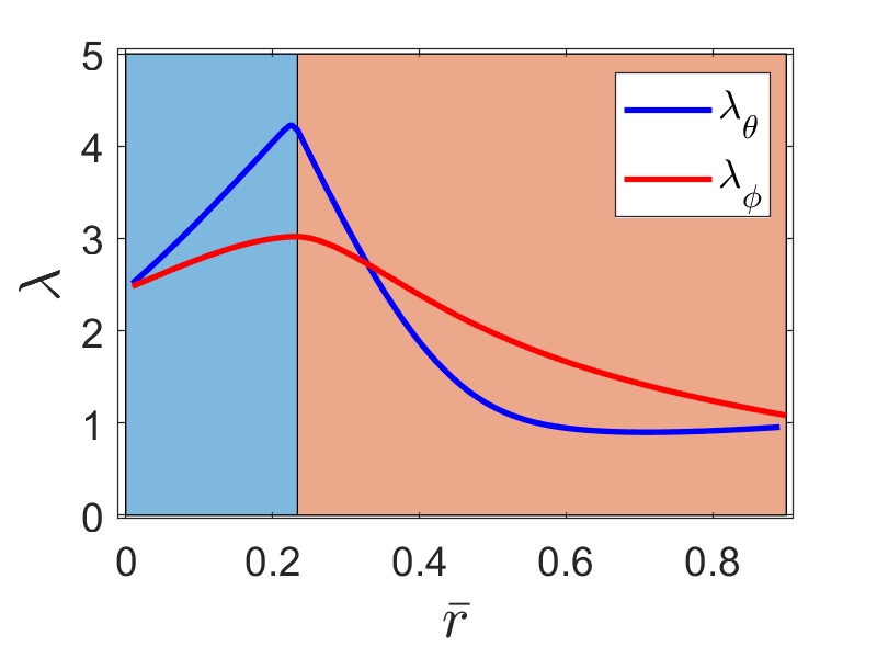
To characterize the deformation of the membrane, using a template, we inscribed circles, separated by radians along the meridional direction, on the stretched membrane, as shown in the inset of Fig. 3(a). The membrane was removed from the ball, and the image on the undeformed membrane was analyzed to characterize the deformation. The displacement of a point at distance from the center of the undeformed membrane was measured and both are normalized by the radius of the sphere, specifying the deformation , as shown in Fig. 3(a). Fig. 3(b) shows the principal stretches, as defined by Eqs. (9) and (10).
Although the two methods of realizing the invagination differ in that method 1 imposes a strong pre-stretch while method 2 does not, our measurements indicate that the final configurations are nonetheless essentially the same.
3 Modeling the invagination
In this section, we present the mathematical models which describe the deformation of the elastic membrane on the sphere involving Coulomb friction. When the membrane loses contact with the sphere, it is still in tension and is strictly under the sphere without making contact with it. The tension in the membrane rapidly relaxes to zero, below which point the membrane is stress free. In this study, we focus only on the portion of the membrane which is in contact with the sphere. We first describe the force balance equation on the elastic membrane, and then present the hyper-elastic models used to calculate the forces, and finally we present our algorithm for the solution, followed by numerical results.
3.1 Force balance
Our goal here is to identify the forces at play and to examine the conditions for the stability of the invagination. The system under consideration is a rigid sphere, partially covered by an elastic membrane as shown in Fig. 1. The configuration there is stable; the sphere is entrapped by the membrane and external forces must be applied to separate the two.

A schematic is shown in Fig. 4. The sphere with radius is at rest with its center at the origin. Its surface exerts not only a normal force, but also a tangential friction force, with friction coefficient . The initially undeformed elastic membrane is flat, regarded here for simplicity as circular in shape, with thickness . It is then stretched and placed on the sphere so as to cover a portion of the sphere, as shown in Fig. 4. The experimental details for producing the stable invagination are given in Section 2.
We assume that the system has cylindrical symmetry about the -axis. We denote the points on top and bottom of the sphere as the north and south poles, respectively; great circles passing through the poles form the meridians along which latitude is measured, perpendicular to these are the lines of latitude, along which the azimuth is measured. Using the standard spherical coordinate notation, distance from the north pole is multiplied by the polar angle along a meridian, and points along the azimuth are identified by the angle . The undeformed elastic membrane is a flat disc, where distance from the center in the plane is measured by , distance perpendicular to the plane is measured by .
When the deformed membrane forming the invagination is on the sphere and the system is in equilibrium, the net force on any element of the membrane must vanish. There will be stress in the membrane, with principal stress vectors in the tangential meridional, the tangential azimuthal and the normal directions. The net force on any element of the membrane with volume exerted by the surrounding membrane is
| (2) |
with components in all three principal directions. In addition to , there will be a normal force per area exerted by the sphere on the membrane, normal to the sphere, and a friction force per area in the meridional direction in equilibrium. Due to cylindrical symmetry, there will be no friction force in the azimuthal direction. If the stress vectors in the meridional and azimuthal directions are multiplied by the thickness of the membrane divided by the sphere radius, they give and , the components of the tangential force per area due to stress on the membrane in the meridional and azimuthal directions, respectively.
The net force in the azimuthal direction is zero due to symmetry and the net force in the normal direction is zero by Newton’s third law. Force balance in the meridional direction requires that
| (3) |
where denotes the (areal) friction force density, and
| (4) |
denotes the elastic force density along the meridian.
Friction plays a key role in the system. During the formation of the invagination, initially, as the membrane is pulled downward, it slips on the sphere with increasing in the northern hemisphere for both methods 1 and 2. After the stretching, as the tension in the membrane is reduced, the membrane slips again - but now towards the north pole with decreasing in some - but not all - regions on the sphere. As the membrane slips, a tangential friction force density in the meridional direction is exerted by the sphere on the membrane - the sign of the force depends on the direction of the slip; the magnitude is determined, in the simplest approximation, by the kinetic friction coefficient. The membrane moves as long as the elastic force density is greater than . As the membrane slips, decreases, and when , the membrane comes to rest at that point. To move the membrane at rest requires a force greater than the maximum provided by static friction.
Experimental observations indicate that the sliding membrane does not come to rest all at once; regions near the equator continue slipping, while the region near the north pole is at rest. Although the dynamics of the boundary between the stationary and moving parts of the membrane is intriguing, due to the complexity of dynamic friction [5], we will not consider it here. For simplicity, we ignore the difference between static and kinetic friction, assume that , but stress that in the static case, the relation denotes only the maximum possible friction force density that the sphere can provide. Explicitly, the friction force density satisfies
| (5) |
where, in our case, the normal force density is given by
| (6) |
We note that and contribute to both the net normal and net meridional force density. The force balance equation that the system must satisfy, in the case of a stable invagination, becomes
| (7) |
Finally, it is interesting to consider the net force exerted by the sphere on the entire membrane. The horizontal component of the net force is zero due to the cylindrical symmetry, and the vertical component is
| (8) |
If the total vertical force on the membrane is positive, the membrane will accelerate away from the sphere, and no stable invagination is realized. If the total vertical force on the membrane is negative, the center or mass of the membrane will accelerate towards the south pole. Therefore, the stable invagination is attained only if the total vertical force is zero.
3.2 Hyperelastic strain energies and forces
The components and are not independent, but are related through stretches in the membrane. Details are provided by models of elasticity. In order to gain a thorough understanding of the deformation associated with the invagination, we consider three elasticity models: Mooney-Rivlin hyperelastic model in the Hookean limit, the Neo-Hookean limit, and the Gent model. We use the proper Cauchy stress throughout.
In spherical coordinates, the principal stretches tangential to the sphere are
| (9) |
and
| (10) |
where is the distance to the north pole after the deformation, and is the distance to the north pole in the underformed state. We assume that the deformation is isochoric; then
| (11) |
With the stretches and defined, we can find the corresponding stresses from the various models of elasticity.
The hyperelastic incompressible Mooney-Rivlin strain energy density has the form [6, 7, 8]
| (12) |
where
| (13) |
and is the shear modulus, and
| (14) | |||||
| (15) |
are the two invariants of the left Cauchy-Green deformation tensor. If , it gives the Neo-Hookean energy density
| (16) |
In the limit of small strains, we have the Hookean energy density,
| (17) |
The Gent elasticity model takes into account the finite extensibility [9], with
| (18) |
where represents the maximum value of allowed by the system in the absence of failure. In the limit as , the Gent model reduces to the Neo-Hookean model.
The tangential force density components and , in terms of the stretches, are
| (19) |
and
| (20) |
Substitution of Eqs. (19) and (20) into Eq. (7) gives the inequality in terms of whose solution provides the detailed description of the elastic deformation. We note that the shear modulus plays no role in the invagination.
3.3 Numerical algorithm and results
Our goal is to find the stable deformation of the membrane , for which Eq. (7) must be satisfied. This requires a non-standard approach, which we now describe. All the lengths are nondimensionalized by the radius of the sphere , so , and . We first prescribe the portion of the membrane in contact with the sphere by , and the point on the sphere , where the membrane loses contact. In this example, we have set , , which are in rough agreement with experiments. We also prescribe the initial displacement of the membrane. In particular, we use an initial displacement of the membrane which is in the neighborhood of the final displacement, which has been suggested by experiments. Given a friction coefficient , we implement the following psudeodynamics
| (21) |
where is the position of membrane at undeformed position at time step , and
| (22) |
That is, the point on the membrane does not move if is less than the maximum frictional force, and the point moves either away from or towards the north pole if overcomes the maximum frictional force, and the direction of motion depends on the sign of . We have used 100 equally spaced points between and . All derivatives are approximated with a centered difference scheme.
After equilibrium is reached, the total vertical force exerted on the membrane by the sphere can be evaluated by Eq. (8). If is different from zero, we adjust the value of the friction coefficient . Explicitly, we increase if , and decrease otherwise, until the total vertical force on the membrane vanishes.
We remark that the equilibrium solution is highly sensitive to the initial condition, so is the friction coefficient which stabilizes the invagination.
Fig. 5 shows the numerical results from the Hookean, Neo-Hookean and Gent models. The results from three different models are qualitatively the same, with the main difference that they require different values of friction coefficient to stabilize the invagination. Among the three models, the Hookean requires the largest friction coefficient, and Neo-Hookean requires the smallest friction coefficient. The boundary of the two background colors on the figures marks the change of direction of the tangential force from elasticity, or equivalently the change of direction of the frictional force. The boundary also coincides with the location where the curve describing the deformation curve changes its concavity (left column of Fig. 5), where the two stretches reach their maxima(middle column of Fig. 5). We note that it is not at the north pole where the membrane is maximally stretched, but rather at an angle close to , where the membrane pulls the neighboring regions both sides towards each other. The sphere pushes the membrane upward with increasing force from the north pole to the point with maximum stretch, where the force changes direction and pulls the membrane downward towards the point where the membrane loses contact with the sphere, as shown in right column of Fig. 5. Remarkably, in the equilibrium configuration, the tangential force is in balance with the maximum friction force everywhere, except at a finite number of discrete points where the stretches reach a local extremum and the friction force changes direction. Any decrease of the friction coefficient from its thus found equilibrium value will render the invagination unstable.

Hookean


NeoHookean


Gent

4 The situation in 2D
It is interesting to ask whether such an invagination can be realized with an elastic membrane and a circular cylinder. A quick experiment with a membrane on a circular cylinder shows that the answer is no. If the cylinder’s axis is horizontal, the membrane can’t stay on the cylinder under the midplane without an external force, which is in stark contrast with the spherical case, where the hoop stress from azimuthal direction can keep the membrane against the sphere below the equator. Second, in cylindrical geometry, the force balance equation reads
| (23) |
where is the force per length. The solution for at any angle is bounded by
| (24) |
where is the tension at the top of the cylinder where . The total vertical force on the membrane from the cylinder can be written as
| (25) | |||||
From Eq. (24), since , the force on the membrane will be always positive. Thus there is no elastically stabilized invagination in 2D, where the hoop stress from azimuthal direction is missing.
5 Discussion and Summary
By conducting experiments using regulation size table tennis balls and dental dams, we have realized elastically stabilized spherical invaginations. We used two approaches to form the invagination; they gave similar deformations of the elastic membrane. Friction plays a key role in stabilizing the system.
Using , we obtained the governing inequality for the elastic deformation of the membrane on the sphere. The forces at play are expressed in terms of stretches in the membrane. We used three elastic models to describe the invagination; crude agreement with experiments was found. Although the inequality was used to evolve the dynamics, remarkably, the solution obeys the equality at almost every point.
Both the experimental data and the numerical solutions indicate that the maximum stretch of the membrane occurs at , where the both frictional force and vertical component of the vertical force on the membrane change direction. Due to the highly nonlinear nature of the problem, the equilibrium solution and the required minimum friction coefficient are strongly dependent on initial conditions, or equivalently, on the process establishing the invagination.
We note the close similarity of the invagination of the membrane and the table tennis ball and the invagination of the membrane and a coin. In the latter case, the membrane was nearly uniformly stretched on top of the coin, and the stretch slowly decreases to a relaxed state under the coin. The invagination was stabilized by the friction force between the vertical edge of the coin and the membrane. Here, the vertical downward force on the membrane is from the lower part of the sphere, below the latitude where the membrane is maximally stretched.
When releasing the ball from the membrane, there is no vertical force to overcome, since the the total vertical force on the sphere exerted by the membrane is zero. However, there is hoop stress must be overcome. The retracting force must be sufficiently large to deform the membrane and increase the radius of the bottom opening to the radius of the sphere. The sphere may also be released if the elastic and frictional properties of the membrane changed. In addition to the experiments described here, we have also realized spherical invaginations using other membranes (balloons, condoms, liquid crystal elastomers) and spherical rigid bodies (marbles, push pins, ball chains).
Here we have only focused on the basic mechanism of the invagination and considered only the portion of the membrane in contact with the sphere. Modeling the entire membrane would give a more complete description of the invagination.
Acknowledgments
This work was supported by the Office of Naval Research through the MURI on Photomechanical Material Systems (ONR N00014-18-1-2624) and Air Force contract FA8649-20-C-0011 as part of the STTR AF18B-T003 Electronically Dimmable Eye Protection Devices (EDEPD) program.
References
- [1] Stillwell, W. An Introduction to Biological Membranes. Elsevier Scientific (2016).
- [2] Meng, F., Doi, M., Ouyang, Z. et al. The ‘Coin-Through-the-rubber’ Trick: An Elastically Stabilized Invagination. J Elast. 123, 43–57 (2016).
- [3] L. Euler, Methodus inveniendi lineas curvas maximi minimive proprietate gaudentes, sive solutio problematis isoperimetrici latissimo sensu accepti, Additamentum I (De curvis elasticis) 245–320 (1744).
- [4] Varenberg M., Varenberg A. Table Tennis membrane: Tribological Characterization, Tribol. Lett. 47, 52-56 (2012).
- [5] Liu, Y.F. et al. Experimental comparison of five friction models on the same test-bed of the micro stick-slip motion system, Mech. Sci. 6, 15-28 (2015).
- [6] Mooney, M., A theory of large elastic deformation, Journal of Applied Physics, 11(9), 582–592 (1940).
- [7] Rivlin, R. S., Large elastic deformations of isotropic materials. IV. Further developments of the general theory, Philosophical Transactions of the Royal Society of London. Series A, Mathematical and Physical Sciences, 241(835), 379–397 (1948)
- [8] Audoly, B., Pomeau, Y.: Elasticity and Geometry: From Hair Curls to the Non-linear Response of Shells. Oxford University Press, Oxford (2010).
- [9] Gent, A.N., A new constitutive relation for membrane, Rubber Chemistry and Technology, 69, 59–61 (1996).